Development of Fractal Pattern Making Application using L-System for
Enhanced Machine Controller
Alexander A S Gunawan1, Jimmy Linggarjati2, and Yandi Wijaya1 1
Mathematics Department, School of Computer Science, Bina Nusantara University, Jakarta, Indonesia 2
Computer Engineering Department, Bina Nusantara University, Jakarta, Indonesia Sent offprint requests to: [email protected]
Abstract. One big issue facing the industry today is an automated machine lack of flexibility for customization because it is designed by the manufacturers based on certain standards. In this research, it is developed customized application software for CNC (Computer Numerically Controlled) machines using open source platform. The application is enable us to create designs by means of fractal patterns using L-System, developed by turtle geometry interpretation and Python programming languages. The result of the application is the G-Code of fractal pattern formed by the method of L-System. In the experiment on the CNC machine, the G-Code of fractal patternwhich involving the branching structure has been able to run well.
1 Introduction
Smid [1] stated that the CNC (Computer Numerically Controlled) machines are the development of manual machines which using a microprocessor to control it. CNC machine itself is a machine tool which is capable of automatically forming a pattern of computer-assisted design. The CNC machines use command code of the computer and no longer use human power to run it.
Equipped by CAM (Computer Aided Manufacturing) software, CNC machines can make the drawing design of objects, created by the help of CAD software (Computer Aided Design). Nevertheless Bovill [2] stated in conceptual design stage, the initial design stage, in which the process is characterized by uncertain idea, CAD (Computer Aided Design) is rarely used application. At the conceptual design stage, designers usually create many ideas and turn it into a drawing sketch by only the help of a paper and pencil. CAD (Computer Aided Design) is rarely used at this stage because it requires a complete definition, concrete, and precise for geometric design that is usually done at a later stage. Therefore, it should be sought the solution to integrate the conceptual design stage with CAD software to create drawing sketch of desired design using computer directly.
One solution, proposed by Soo [3], is integration of the conceptual design stage with CAD into one application software. This solution is come from the observation that many jewellery products are adopting attractive pattern of natural objects, which can be designed by fractal geometry. The proposed solution by Soo [3] is only for rapid prototyping, which the fractal
geometry implemented using Iterated Function System, and the solutions have not been implemented in application software.
To generate the fractal design patterns, actually many methods that can be applied, one of them is L-System method, which can be implemented easily in programming by the help of the turtle geometry interpretation. By above reasoning, this research is intended to developing customized application software for CNC machines which can be used to create design patterns using fractal geometry automatically based on input from users.
2 Enhanced Machine Controller
Enhanced Machine Controller or abbreviated as EMC ref. [4] is computer software for controlling CNC machines such as milling machines, lathes, plasma cutters, cutting machines, robots, hexapods, and others. EMC is open source software which licensed under GNU General Public License and GNU Lesser General Public License (GPL and LGPL).
EMC2 is the progress of EMC software. There are four major components to the EMC2 software, namely: motion controller, controller I/O discrete modules to coordinate controllers and graphical user interface. And especially in EMC2, there is a facility called the HAL (Hardware Abstraction Layer) ref. [5] which allows adjustment without recompiling EMC2 configuration so that it will simplify the interface to the hardware. Because of the nature of open source, the EMC2 facilitate the DOI: 10.1051/
C
Owned by the authors, published by EDP Sciences, 2014 ,
/
0 00 32 (2014) 2 01
68 epjconf EPJ Web of Conferences
4 6 800032
customization process for developing specific application software.
Figure 1 shows a simple block diagram showing the EMC2 system for 3-axis machine. The diagram shows the stepper motor system. PC with Linux as the operating system is used to control the stepper motors drive by sending a signal through the printer port (parallel). The signals (pulses) make the drive stepper motors moving.
Fig. 1. EMC2 Controlled Machine
2.1 AXIS Interface
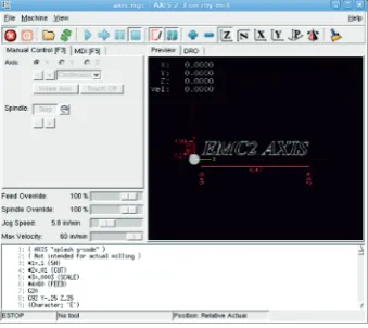
AXIS interface is one of the display interfaces of EMC2. AXIS is the default interface to EMC2 which is actively developed by its users. AXIS interface can be reconfigured by adding the Virtual Control Panel to adjust the shape of the display when running the EMC2 program to suit the needs of the user. AXIS can be seen in figure 2 below:
Fig. 2. AXIS Interface
2.2 Python Programming Language 2.6
Application software for L-System methods is developed using Python programming language 2.6. Python run on EMC2-AXIS over Ubuntu Linux operating system. Python ref. [6] is a dynamic programming language that supports object-oriented programming. In addition, the language is easy to use because it has a clear structure and grammar and also has extensive libraries. Besides Python language can be integrated with other languages such as C / C + + and Java.
2.3 G-Code
G-Code ref. [4] is a programming language for CNC machine which is closely related to graphics and vector. This language is used as a connector between the machine tool and CNC software that resides on computer. The machine will follow the movements of the design which written in G-Code. G-Code programming language is written in a file with the extension *.ngc (Numerical G-Code). Here are some examples of G-Code language along with their respective functions:
Code Description G0 Rapid motion
G1 Coordinated motion ("Straight feed") G2, G3 Coordinated helical motion ("Arc feed") G4 Dwell (no motion for P seconds)
G38.2…G38.5 Straight probe G80 Cancel motion mode
G81, G82 Drilling cycle without (with) dwell G83, G73 Peck and Chip-break drilling cycles G85, G89 Boring cycle without (with) dwell G33 Spindle-synchronized motion G33.1 Rigid tapping
G76 Multiphase lathe threading cycle
2.4 Specification of CNC Machines
Specification of the used CNC machines is as follows:
Minimum Track Width 0.5 mm Minimum Isolation Width 0.5 mm Minimum Drill Hole Diameter 0.6 mm
Working Area (X/Y/Z) 500 mm x 400 mm x 50 mm Resolution 0.1 mm
Travel speed (max) 200 mm per second X positioning system dc-servo motor
Y/Z positioning system 5-phase stepper motors Dimensions (W x H x D) 600 mm x 500 mm x 1500 mm
Weight 300 kg
Power supply 220 V, 60 Hz/500 VA
The used CNC machine can be seen in figure 3 below:
3 L-System Methods
According to Mandelbrot [7], fractal derived from the Latin adjective "fractus" which means crushed or cracked and then he defines a fractal as "the set which the Hausdorf dimension exceed its topological dimension". L-System is one of techniques for implementing fractals. Furtehrmore Prusinkiewicz [8] explains that the main concept of the L-System is rewriting. Rewriting mechanism in the L-System was introduced by Aristid Lindenmayer in 1968. The L-System consists of: symbols which can be used to create string, collection of production rules for transforming symbols to string, initial string value for the start of construction called as Axiom, and mechanism for translating the resulting string into the geometric structure. For the translation stage to the geometric structure, the developed application use turtle geometry interpretation ref. [9].
3.1. Turtle Geometry
Prusinkiewicz [8] explain that the turtle is defined as a triplet (x, y, α) where the Cartesian coordinates (x, y) represents the position of the turtle and the angle α indicates the direction for the turtle. If given step length d and angle δ, the turtle can interpret the symbols in Table 1 below:
Table 1. Interpretation Turtle Table
Symbol Interpretation
F, X
Moving forward as d steps. Status of the turtle turned into (x', y', α), where x'= x + d cos α and y' = y + d sin α. Line between the point (x, y) and (x', y') is drawn.
f Moving Forward as d steps
without drawing a line.
+
Rotates to the left as δ.. The next status turtle to (x, y, α + δ). Positive orientation is rotated clockwise.
– Rotates to the right as δ.. The
next status turtle to (x, y, α - δ).
According to the above rules, the turtle interprets the character string as a sequence of line segments. However, the plant or tree pattern is dominated by the branching structure ref. [8], so that two new symbols are introduced to define a branch that is '[' and ']' which their means described in Table 2:
Table 2. Interpretation of Symbol '[' and ']'
Symbol Interpretation
[ Saving the current position and
starting a new branch.
] Retrieving the last saved position
and moving again from there.
In addition to the symbols contained in Table 1 and Table 2, the turtle will not interpret into anything and just stand still when seeing the other symbols.
4 Implementation
For the implementation of the application software requires several steps ref. [10]:
1. Developing Virtual Control Panel, integrated with AXIS through PyVCP. This step produces a file with the extension *.xml
2. Connecting PyVCP with EMC2 through the facilities of HAL (Hardware Abstraction Layer). This step results in file with extension *.hal
3. Resetting the configuration file axis_mm.ini of CNC machine in order to read the *.xml and *.hal files, produced in (1) and (2). Modification is performed on PYVCP and POSTGUI_HALFILE.
4. Developing the L-System program in the Python programming language, which generate G-Code in a file with the extension *.ngc
5. Executing *.ngc file from AXIS Interface.
These steps are explained further in the following section:
4.1. Developing Virtual Control Panel
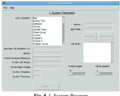
Developing the L-System GUI as in figure 4 required creation *.xml file to set the GUI display. PyVCP (Python Virtual Control Panel) is required to perform a virtualization panel on EMC2. The virtualization panel is needed because EMC2 only recognize the panel as an object. In our approach, the virtualization panel developed by PyVCP is used as connector between the EMC2 to the main program of L-System. Modification related this step in *.xml file is by adding <pyvcp> tag and closed with the </ pyvcp> tag.
Fig. 4. L-System GUI
4.2. Connecting PyVCP with EMC2 using HAL (Hardware Abstraction Layer)
to the connecting signal through specific ports on EMC2 can get to CNC machine.
4.3. Resetting the configuration file of CNC machine
In EMC2-Axis software, there is *.ini (initial) files which storing and calling all existing settings for initiating the EMC2-Axis software. This file can be accessed and modified by the user. For the implementation of the application software, it is used axis_mm.ini file and modifies this file. Modification is mainly intended to allow EMC2 software can read the *.xml and *.hal produced in previous steps. This modification is performed on PYVCP and POSTGUI_HALFILE.
4.4. Developing the L-System Program
L-System methods are implemented via Python programming language 2.6 in Ubuntu Linux operating system. In addition, it is used Tkinter ref. [11] for creating Python GUI to input the data on L-System. Further EMC2-Axis is calling a Python program through MDI facility commands on HALUI (Hardware Abstraction Layer) and then executes the G-Code command: M101 M199 (User-defined M-codes).
The L-System program generates file in the form of G-Code (file with extension *.ngc). In the implementation, the L-System program is named as M101 and the result is 101.ngc file whose contents can be viewed as follows:
O101 Sub G20 F8.0
G1 X 0.000000 Y 0.000000
(Coordinats in the G-Code depends on design pattern)
G1 X 1.000000 Y 1.000000 O101 Endsub
M2
In figure 5, it can be seen L-System program developed with Python and Tkinter.
Fig. 5. L-System Program
4.5. Executing G-Code from AXIS Interface
After *.ngc which contains G-Code created then it can be invoked via MDI commands in HALUI (Hardware Abstraction Layer) and execute G-Code commands: O101 ... O199 (Call subroutines). To do this, the user can simply click the Run button in figure 4 L-System GUI.
5 Results
For simulation, there are eleven fractal design patterns for testing the application, which running well. The following table are some examples of fractal design patterns obtained after running L-System program using the specified rule in Table 3 below:
Table 3. Results of Program Testing
Fractals Type Result
Box (n = 3)
Axiom: F-F-F-F
Rule:
F→FF-F-F-F-FF
Dragon Curve (n = 10)
Axiom: FX
Rule:
X→X+YF
Y→FX–Y
F→F
Island And Lakes (n = 2)
Axiom: F+F+F+F
Rule:
F→F+f–
FF+F+FF+Ff+FF
– f+FF– F– FF– Ff–FFF
f→ffffff
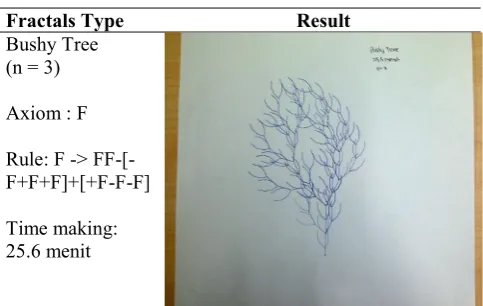
Table 4. Results from CNC Machine
Fractals Type Result
Bushy Tree (n = 3)
Axiom : F
Rule: F -> FF-[-F+F+F]+[+F-F-F]
Time making: 25.6 menit
6 Conclusions
From the results of the application software, some conclusions are obtained as follows:
a. EMC2 can be used to run CNC machines well and because it is open source, users can make the customization to adjust EMC2 according to their needs.
b. L-System methods with the help of turtle geometry interpretation can be used to form a fractal design patterns. The design patterns are useful in conceptual design stage which consuming time and cost.
References
1. P. Smid, CNC Programming Handbook 2nd Edition, New York: Industrial Press Inc (2003)
2. C. Bovill, Fractal Geometry as Design Aid, Journal for Geometry and Graphics Volume 4 No 1, 71-78 (2000)
3. S.C. Soo, K.M. Yu, Rapid Prototyping Using Fractal Geometry, 424-431 (2001)
4. The EMC Team, User Manual V 2.4. http://www.linuxcnc.org/docs/EMC2_User_Manual. pdf (2011)
5. T. Starovešk, D. Brezak, T. Udiljak, D. Majetić,
Implementation of A Linux-Based CNC Open Control System, 12th International Scientific Conference on Production Engineering – CIM (2009)
6. D. Ascher, A. Martelli, A. Ravenscroft, Python Cookbook, USA: O’Reilly (2005)
7. B.B. Mandelbrot, The Fractal Geometry of Nature, New York: W.H. Freeman And Company (1983)
8. P. Prusinkiewicz, A. Lindenmayer, The Algorithmic Beauty of Plants, New York: Springer-Verlag (2004)
9. I. Zammouri, B. Ayeb, Fractal Shapes Description with Parametric L-systems and Turtle Algebra,
World Academy of Science, Engineering and Technology 34 (2007)
10. A.A.S Gunawan, J. Linggarjati, Pengembangan Program Aplikasi Enhanced Machine Control dengan Python untuk Metode Interpolasi Newton, Jurnal ComTech, Vol 03 / No 01 / June 2012
11. J.W. Swipman, Tkinter 8.4 Reference: a GUI for Python, Mexico: New Mexico Tech (2010)
![Table 2. Interpretation of Symbol '[' and ']'](https://thumb-us.123doks.com/thumbv2/123dok_us/8205555.1370714/3.595.319.532.523.689/table-interpretation-symbol.webp)