STOCK # 0293884
User Guide
functions, or features, at any time, without notice.
NEC America, Inc. has prepared this document for use by its em-ployees and customers. The information contained herein is the property of NEC America, Inc. and shall not be reproduced without prior written approval from NEC America, Inc.
Copyright 1998
NEC America, Inc. VisuaLink 128/VisuaLink 384 TYPE OF SERVICE
The VisuaLink 128 and the VisuaLink 384 are stand-alone devices that allow multimedia conferencing by transmitting video, audio and data to remote locations over the ISDN Basic Rate interface. The VisuaLink 128 and VisuaLink 384 connect to the ISDN digital network through separately-registered NTI equipment. They provide POTS ports which allow a customer-provided 2500-type telephone access to the digital network. This equipment complies with Part 68 of the FCC Rules. The equipment label will appear on the rear exterior panel of the unit and will provide the FCC Registration Number, NEC trade name, model number, serial number or date of manufacture and the country of origin.
TELEPHONE COMPANY PROCEDURES
The goal of the telephone company is to provide you with the best service it can. In order to do this, it may occasionally be necessary for them to make changes in their equipment, operations, or procedures. If these changes might affect your service or the operation of your equipment, the telephone company will give you notice, in writing, to allow you to make any changes necessary to maintain uninterrupted service.
If you have any questions about your telephone line, such as how many pieces of equipment you can connect to it, the telephone company will give you notice, in writing, to allow you to make any changes necessary to maintain uninterrupted service.
If any of your telephone equipment is not operating properly, you should immediately remove it from your telephone lines, as it may cause harm to the telephone network. If the telephone company notes a problem, they may temporarily discontinue service. When practical, they will notify you in advance of this disconnection. If advance notice is not feasible, you will be notified as soon as possible. When you are notified, you will be given the opportunity to correct the problem and informed of your right to file a complaint with the FCC. In the event repairs are ever needed on your Visualink 128 or VisuaLink 384, they should be performed by NEC America, Inc. or an authorized representative of NEC America, Inc. For information contact:
NEC America, Inc. 1555 W. Walnut Hill Lane Irving, Texas 75038-3797 USA
972-751-7000
FCC REQUIREMENTS FOR CONNECTION OF TELEPHONE SYSTEMS
In order to connect this system to the telephone network, provide the telephone company with: • the quantities and USOC numbers of the required jacks (shown below);
• the sequence in which the trunks are to be connected; • the facility interface codes by position; and
• the ringer equivalence number or service code, as applicable, by position
MFG’s Port ID
USOC Jack Connector
REN/Service Code
Facility Interface Code
# CO
Ports # Stations Registration #
VisuaLink 128 N/A 6.0P 02IS5 1 1 AY5JPN-32617-XD-N
To ensure that certified equipment is attached correctly, and only to the networks of participating carriers, the following statement shall accompany each unit of certified equipment offered for sale. This statement must be included conspicuously in written or electronic format, at or near the front of each copy of the operating manual, or accompany other technical information, or be included as a separate sheet. The required statement is:
CP-01, Issue 8, Part I Section 14.1
NOTICE: The Industry Canada label identifies certified equipment. This certification means that the equipment meets certain telecommunications network protective, operational and safety requirements as prescribed in the appropriate Terminal Equipment Technical Requirements document(s). The Department does not guarantee the equipment will operate to the user's satisfaction.
Before installing this equipment, users should ensure that it is permissible to be connected to the facilities of the local telecommunications company. The equipment must also be installed using an acceptable method of connection. The customer should be aware that compliance with the above conditions may not prevent degradation of service in some situations.
Repairs to certified equipment should be coordinated by a representative designated by the supplier. Any repairs or alterations made by the user to this equipment, or equipment malfunctions, may give the telecommunications company cause to request the user to disconnect the equipment.
Users should ensure for their own protection that the electrical ground connections of the power utility, telephone lines and internal metallic water pipe system, if present, are connected together. This precaution may be particularly important in rural areas.
CAUTION: Users should not attempt to make such connections themselves, but should contact the appropriate electric inspection
MODEL CERTIFICATE NUMBER CERTIFICATION NUMBER
VisuaLink 128 19318 140 9004A
Table of Contents
Chapter 1
Introducing Your VisuaLink ... 1-1
Applying for ISDN BRI ... 1 -1 Unpacking ... 1-2
Chapter 2
Introduction of VisuaLink ... 2-1
About your VisuaLink ... 2-1 Front Panel Description ... 2-2 VisuaLink 128 Rear Panel Description ... 2-3 VisuaLink 384 Rear Panel Description ... 2-4 Remote Controller ... 2-9
Chapter 3
Initial Setting and Operation Checking ... 3-1
Chapter 4
Application Setup... 4-1
Guidelines ... 4-1 Hardware ... 4-2 Software Setup ... 4-23 Setting Up your ISDN Line Information ... 4-24 Optional User Settings ... 4-27
Chapter 5
System Parameter/Environment Setting... 5-1
Environment Setting Menu... 5-1 Video Setting... 5-6 Audio Setting... 5-8 Data Setting ... 5-11 Communication Setting ... 5-13 Local Setting ... 5-15 Maintenance Settings ... 5-29
Chapter 6
About Calling ... 6-1
Place a Manual Call ... 6-1 Set Speed Dial Number ... 6-6 End a Call ... 6-16 Answer a Call ... 6-17
Chapter 7
Conference Mode ... 7-1
Chapter 8
Operation Method ... 8-1
System Status... 8-1 Volume Control ... 8-3 Muting Your Microphone... 8-4 Switching Monitor Screens ... 8-5 Switching Camera Pictures... 8-7 PIP Functions... 8-10 Send a Snapshot ... 8-11 Camera Functions... 8-13 Using Camera Preset... 8-16 Pointer Display... 8-17
Chapter 9
VisuaLink Troubleshooting Guide ... 9-1
Appendix A Audio/Data/Video Bit Rate Assignment Table ... A-1
Appendix B Software Upgrade Instructions ... B-1
Appendix C CALL Menu Structure... C-1
List of Figures
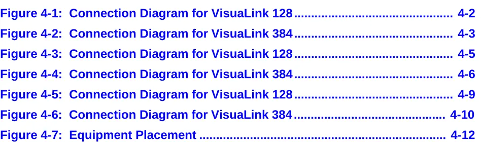
Figure 4-1: Connection Diagram for VisuaLink 128 ... 4-2
Figure 4-2: Connection Diagram for VisuaLink 384 ... 4-3
Figure 4-3: Connection Diagram for VisuaLink 128 ... 4-5
Figure 4-4: Connection Diagram for VisuaLink 384 ... 4-6
Figure 4-5: Connection Diagram for VisuaLink 128 ... 4-9
Figure 4-6: Connection Diagram for VisuaLink 384 ... 4-10
List of Tables
Table 1-1:
Parts List for the VL128 and VL384... 1-2
Table 1-2:
Optional parts to be provided... 1-3
Table 2-1:
VisuaLink 128 and VisuaLink 384 General Parameters ... 2-5
Table 2-2:
VisuaLink 128 and VisuaLink 384 External Interface Parameters.... 2-7
Chapter 1 Introducing Your VisuaLink
1.1 Applying for ISDN BRI
This device cannot be used unless a connection to ISDN BRI Communication Line is provided. Verify that a ISDN line exists before the CODEC is installed.
What to watch out for when filling out an ISDN BRI application:
As defined by Bellcore; the ISDN BRI simplified ordering code is EZ-ISDN1. • The ISDN BRI protocol national ISDN-1.
• The ISDN BRI service must be tariffed and available from the customer’s local central office.
• The D-Channel should not permit X.25 packet data.
• The ISDN BRI service must allow videoconferencing calls to be dialed on either B-Channel or on both simultaneously.
• Both B-Channel must carry circuit switched videoconferencing data. • The ISDN BRI line required one or two different SPID numbers.
• The ISDN BRI service must be automatic Terminal Endpoint Identifiers (TEIs).
Voice and data features: • Flexible calling
• Call forwarding variable • Additional call offering • Call number identification • Redirecting number delivery
A How to Order ISDN BRI Guide has been prepared. This guide should be read thoroughly and forwarded to your Teleco provider. This document is located in
1.2 Unpacking • Opening the Box
Please take out the device without giving any impact on it when opening the box. Please keep the box after opening it, since you may use it when you send the device for repair, maintenance and/or travel.
• The Contents of the Package
The VisuaLink 128 and VisuaLink 384 package contains the following items. Please verify these items are contained the box.
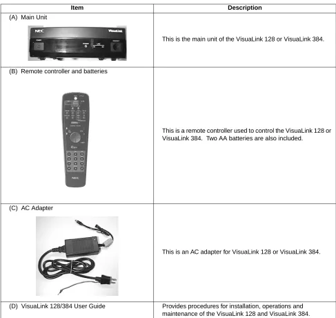
Table 1-1: Parts List for the VL128 and VL384
Item Description
(A) Main Unit
This is the main unit of the VisuaLink 128 or VisuaLink 384.
(B) Remote controller and batteries
This is a remote controller used to control the VisuaLink 128 or VisuaLink 384. Two AA batteries are also included.
(C) AC Adapter
This is an AC adapter for VisuaLink 128 or VisuaLink 384.
Table 1-1: Parts List for the VL128 and VL384 (continued)
(E) Audio Video Cable
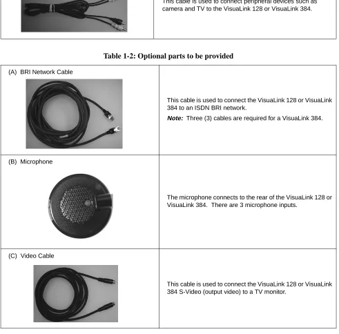
This cable is used to connect peripheral devices such as camera and TV to the VisuaLink 128 or VisuaLink 384.
Table 1-2: Optional parts to be provided
(A) BRI Network Cable
This cable is used to connect the VisuaLink 128 or VisuaLink 384 to an ISDN BRI network.
Note: Three (3) cables are required for a VisuaLink 384.
(B) Microphone
The microphone connects to the rear of the VisuaLink 128 or VisuaLink 384. There are 3 microphone inputs.
(C) Video Cable
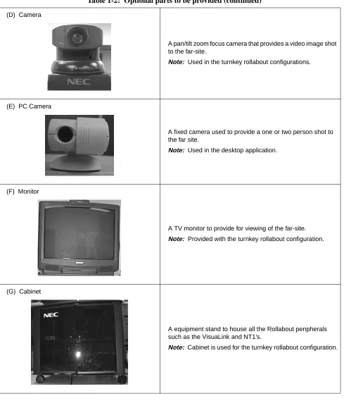
Table 1-2: Optional parts to be provided (continued)
(D) Camera
A pan/tilt zoom focus camera that provides a video image shot to the far-site.
Note: Used in the turnkey rollabout configurations.
(E) PC Camera
A fixed camera used to provide a one or two person shot to the far site.
Note: Used in the desktop application.
(F) Monitor
A TV monitor to provide for viewing of the far-site.
Note: Provided with the turnkey rollabout configuration.
(G) Cabinet
A equipment stand to house all the Rollabout peripherals such as the VisuaLink and NT1’s.
Chapter 2 Introduction of VisuaLink
2.1 About your VisuaLink
The VisuaLink 128 and the VisuaLink 384 are devices that easily realize a multimedia conference by transmitting video, audio, and data to a remote location with the use of BRI service. The VisuaLink 128 and VisuaLink 384 provide a low-end TV conference for a small group of people when connected to a hands-free telephone. In addition, with a connection with a PC, a TV conference using data conference application such as an electric presentation will be available. The VisuaLink 128 and VisuaLink 384 also provide a high-performance model with a built-in echo canceller applicable for video conferences with microphones and speakers in a conference room.
2.1.1 The characteristics of VisuaLink 128 are
• You can use it as a high quality TV phone by connecting a TV, telephone, and video camera.
• You can use it as a serious business videoconference system by connecting optional video camera, microphone, and speakers.
• You can easily operate it from a telephone or a remote controller.
• You can connect any PC model for a conference with a PC. (However, a data conference software is required in your PC. Please contact to sales rep. to get information for what type of software is available for the data conference with the VL128.
2.1.2 The characteristics of VisuaLink 384 are the same as those for the VisuaLink 128 listed above, plus
• It has an internal IMUX.
2.2 Front Panel Description
This section briefly describes names and features of the VisuaLink 128 and VisuaLink 384.
① POWER Switch
The push-button switch is used to turn on and off the main power. When the power is on, the power lamp will be lit.
➁ Remote controller optical receiver
This is a optical receiver, which receives signal from remote controller. ➂ LED Display
Power Lamp (power) : a green light will eluminate when the power is ON. When the VisuaLink is powered OFF, there is no light.
Line connection status lamp (LINE)
LINE B1: Flashing light indicates channel is calling to the remote end. Steady light indicates connection/communicating with the remote end. LINE B2-B6: Flashing light indicates channel is calling to the remote end. Steady light indicates connection/communicating with the remote end. ➃ Head set terminal
The head set jack is used to connect an optional headset.
POWER HEADSET
POWER LINE
B1 B2-B6
2.3 VisuaLink 128 Rear Panel Description
① VIDEO 2 IN (S-Video input): Provides an S-Video input connection for a camera or other video source.
➁ VIDEO 1 IN (NTSC input): Provides a composite input connection for a camera or other video source.
➂ VIDEO 2 OUT (S-Video output): Provides an S-Video output connection to a monitor or other display device.
➃ VIDEO 1 OUT (NTSC output): Provides a composite output connection to a monitor or other display device.
➄ AUDIO IN: Provides a line level audio input from a VCR, audio mixer, other audio transmission device or External Echo Canceller connection.
➅ AUDIO OUT (AUX output): Provides a line level audio output to an amplified speaker, other audio receiver device or External Echo Canceller connection.
➆ MIC 1~3: Mini stereo phono plugs connection for one to three microphones. ➇ SERIAL 1 (RS232C input): Provides a mini din connection conforming to
RS232 for connection to a PC or other data device.
➈ SERIAL 2/ RMT (RS232C input/output): Provides a mini din connection comforming to RS232 for connection to a PC, camera or other RS232 device. ➉ TEL terminal: Provides an RJ11 jack for connecting the VoicePoint or other
two wire telephone.
S/T LINE terminal: Provides an ISDN BRI S interface used to connect to the communication data line.
DC power input terminal: Provides an AC adapter interface for AC power. Grounding terminal: Provides a ground connection at should be connected to earth ground.
+
+
+ +
+
DC IN 5V
+
Serial1 Serial2/RMT O
U T
I N
VIDEO2 VIDEO1 AUDIO
+
+ MIC1 MIC2 MIC3 TEL S/T LINE
① ➁
➂ ➃ ➅ ➆ 11
2.4 VisuaLink 384 Rear Panel Description
① VIDEO 2 IN (S-Video input): Provides an S-Video input connection for a camera or other video source.
➁ VIDEO 1 IN (NTSC input): Provides a composite input connection for a camera or other video source.
➂ VIDEO 2 OUT (S-Video output): Provides an S-Video output connection to a monitor or other display device.
➃ VIDEO 1 OUT (NTSC output): Provides a composite output connection to a monitor or other display device.
➄ AUDIO IN: Provides a line level audio input from a VCR, audio mixer, other audio transmission device or External Echo Canceller connection.
➅ AUDIO OUT (AUX output): Provides a line level audio output to an amplified speaker, other audio receiver device or External Echo Canceller connection.
➆ MIC 1~3: Mini stereo phono plugs connection for one to three microphones. ➇ SERIAL 1 (RS232C input): Provides a mini din connection conforming to
RS232 for connection to a PC or other data device.
➈ SERIAL 2/ RMT (RS232C input/output): Provides a mini din connection comforming to RS232 for connection to a PC, camera or other RS232 device. ➉ TEL terminal: Provides an RJ11 jack for connecting the VoicePoint or other
two wire telephone.
S/T LINE terminal: Provides three (3) ISDN BRI S interfaces to connect to the communication data line.
DC power input terminal: Provides an AC adapter interface for AC power. Grounding terminal: Provides a ground connection at should be connected to earth ground.
+
+
+ +
+
DC IN 5V
+
Serial1 Serial2/RMT O
U T
I
N
VIDEO2 VIDEO1 AUDIO
+
+ MIC1 MIC2 MIC3 TEL LINE 1 LINE 2 LINE 3
① ➁
➂ ➃ ➅ ➆ 11
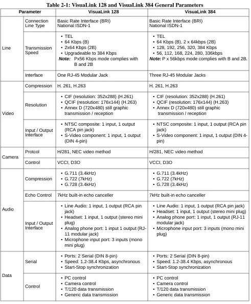
Table 2-1: VisuaLink 128 and VisuaLink 384 General Parameters
Parameter VisuaLink 128 VisuaLink 384
Line
Connection Line Type
Basic Rate Interface (BRI) National ISDN-1
Basic Rate Interface (BRI) National ISDN-1
Transmission Speed
• TEL • 64 Kbps (B) • 2x64 Kbps (2B)
• Upgradeable to 384 Kbps
Note: Px56 Kbps mode complies with B and 2B
• TEL
• 64 Kbps (B), 2 x 64kbps (2B) • 128, 192, 256, 320, 384 Kbps • 56, 112, 168, 224, 280, 336kbps
Note: P x 56kbps mode complies with B and 2B.
Interface One RJ-45 Modular Jack Three RJ-45 Modular Jacks
Video
Compression H. 261, H.263 H. 261, H.263
Resolution
• CIF (resolution: 352x288) (H.261) • QCIF (resolution: 176x144) (H.263) • Annex D (720x480) still graphic
transmission / reception
• CIF (resolution: 352x288) (H.261) • QCIF (resolution: 176x144) (H.263) • Annex D (720x480) still graphic
transmission / reception
Input / Output Interface
• NTSC composite: 1 input, 1 output (RCA pin jack)
• S-Video component: 1 input, 1 output (DIN 4-pin)
• NTSC composite: 1 input, 1 output (RCA pin jack)
• S-Video component: 1 input, 1 output (DIN 4-pin)
Camera
Protcol H/281, NEC video method H/281, NEC video method
Control VCCI, D3O VCCI, D3O
Audio
Compression
• G.711 (3.4kHz) • G.722 (7kHz) • G.728 (3.4kHz)
• G.711 (3.4kHz) • G.722 (7kHz) • G.728 (3.4kHz)
Echo Control 7kHz built-in echo canceller 7kHz built-in echo canceller
Input / Output Interface
• Line Audio: 1 input, 1 output (RCA pin jack)
• Headset: 1 input, 1 output (stereo mini plug)
• Analog phone port: 1 input 1 output (RJ-11 modular jack)
• Microphone input port: 3 inputs (mono mini plug)
• Line Audio: 1 input, 1 output (RCA pin jack) • Headset: 1 input, 1 output (stereo mini plug) • Analog phone port: 1 input, 1 output (RJ-11
modular jack)
• Microphone input port: 3 inputs (mono mini plug)
Data
Serial
• Ports: 2 Serial (DIN 8-pin)
• Speed: 1.2-38.4 Kbps, asynchronous • Start-Stop synchronization
• Ports: 2 Serial (DIN 8-pin)
• Speed: 1.2-38.4 Kbps, asynchronous • Start-Stop synchronization
Control
• PC control • Camera control
• T/120 data transmission • Generic data transmission
• PC control • Camera control
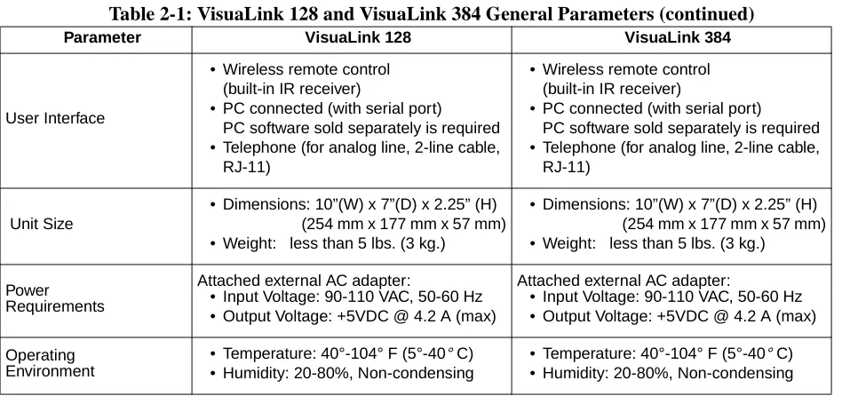
Table 2-1: VisuaLink 128 and VisuaLink 384 General Parameters (continued)
Parameter VisuaLink 128 VisuaLink 384
User Interface
• Wireless remote control (built-in IR receiver)
• PC connected (with serial port) PC software sold separately is required • Telephone (for analog line, 2-line cable,
RJ-11)
• Wireless remote control (built-in IR receiver)
• PC connected (with serial port) PC software sold separately is required • Telephone (for analog line, 2-line cable,
RJ-11)
Unit Size
• Dimensions: 10”(W) x 7”(D) x 2.25” (H) (254 mm x 177 mm x 57 mm) • Weight: less than 5 lbs. (3 kg.)
• Dimensions: 10”(W) x 7”(D) x 2.25” (H) (254 mm x 177 mm x 57 mm) • Weight: less than 5 lbs. (3 kg.)
Power Requirements
Attached external AC adapter:
• Input Voltage: 90-110 VAC, 50-60 Hz • Output Voltage: +5VDC @ 4.2 A (max)
Attached external AC adapter:
• Input Voltage: 90-110 VAC, 50-60 Hz • Output Voltage: +5VDC @ 4.2 A (max)
Operating Environment
• Temperature: 40°-104° F (5°-40° C) • Humidity: 20-80%, Non-condensing
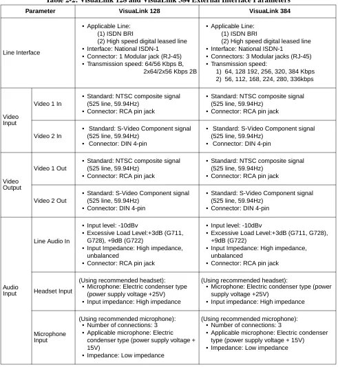
Table 2-2: VisuaLink 128 and VisuaLink 384 External Interface Parameters
Parameter VisuaLink 128 VisuaLink 384
Line Interface
• Applicable Line: (1) ISDN BRI
(2) High speed digital leased line • Interface: National ISDN-1
• Connector: 1 Modular jack (RJ-45) • Transmission speed: 64/56 Kbps B,
2x64/2x56 Kbps 2B
• Applicable Line: (1) ISDN BRI
(2) High speed digital leased line • Interface: National ISDN-1
• Connectors: 3 Modular jacks (RJ-45) • Transmission speed:
1) 64, 128 192, 256, 320, 384 Kbps 2) 56, 112, 168, 224, 280, 336kbps
Video Input
Video 1 In
• Standard: NTSC composite signal (525 line, 59.94Hz)
• Connector: RCA pin jack
• Standard: NTSC composite signal (525 line, 59.94Hz)
• Connector: RCA pin jack
Video 2 In
• Standard: S-Video Component signal (525 line, 59.94Hz)
• Connector: DIN 4-pin
• Standard: S-Video Component signal (525 line, 59.94Hz)
• Connector: DIN 4-pin
Video Output
Video 1 Out
• Standard: NTSC composite signal (525 line, 59.94Hz)
• Connector: RCA pin jack
• Standard: NTSC composite signal (525 line, 59.94Hz)
• Connector: RCA pin jack
Video 2 Out
• Standard: S-Video Component signal (525 line, 59.94Hz)
• Connector: DIN 4-pin
• Standard: S-Video Component signal (525 line, 59.94Hz)
• Connector: DIN 4-pin
Audio Input
Line Audio In
• Input level: -10dBv
• Excessive Load Level:+3dB (G711, G728), +9dB (G722)
• Input Impedance: High impedance, unbalanced
• Connector: RCA pin jack
• Input level: -10dBv
• Excessive Load Level:+3dB (G711, G728), +9dB (G722)
• Input Impedance: High impedance, unbalanced
• Connector: RCA pin jack
Headset Input
(Using recommended headset): • Microphone: Electric condenser type
(power supply voltage +25V) • Input impedance: High impedance
(Using recommended headset):
• Microphone: Electric condenser type (power supply voltage +25V)
• Input impedance: High impedance
Microphone Input
(Using recommended microphone): • Number of connections: 3 • Applicable microphone: Electric
condenser type (power supply voltage + 15V)
• Impedance: Low impedance
(Using recommended microphone): • Number of connections: 3
• Applicable microphone: Electric condenser type (power supply voltage + 15V)
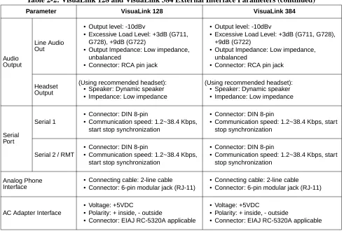
Table 2-2: VisuaLink 128 and VisuaLink 384 External Interface Parameters (continued)
Parameter VisuaLink 128 VisuaLink 384
Audio Output
Line Audio Out
• Output level: -10dBv
• Excessive Load Level: +3dB (G711, G728), +9dB (G722)
• Output Impedance: Low impedance, unbalanced
• Connector: RCA pin jack
• Output level: -10dBv
• Excessive Load Level: +3dB (G711, G728), +9dB (G722)
• Output Impedance: Low impedance, unbalanced
• Connector: RCA pin jack
Headset Output
(Using recommended headset): • Speaker: Dynamic speaker • Impedance: Low impedance
(Using recommended headset): • Speaker: Dynamic speaker • Impedance: Low impedance
Serial Port
Serial 1
• Connector: DIN 8-pin
• Communication speed: 1.2~38.4 Kbps, start stop synchronization
• Connector: DIN 8-pin
• Communication speed: 1.2~38.4 Kbps, start stop synchronization
Serial 2 / RMT
• Connector: DIN 8-pin
• Communication speed: 1.2~38.4 Kbps, start stop synchronization
• Connector: DIN 8-pin
• Communication speed: 1.2~38.4 Kbps, start stop synchronization
Analog Phone Interface
• Connecting cable: 2-line cable • Connector: 6-pin modular jack (RJ-11)
• Connecting cable: 2-line cable • Connector: 6-pin modular jack (RJ-11)
AC Adapter Interface
• Voltage: +5VDC
• Polarity: + inside, - outside
• Connector: EIAJ RC-5320A applicable
• Voltage: +5VDC
• Polarity: + inside, - outside
2.5 Remote Controller 2.5.1 Basic Operational Buttons
From top left to down followed by top right to down. (a) MENU button
Displays the configuration menus on-screen. (b) CALL button
Displays the line connection menu. (c) HANG UP button
Hangs-up the video conference line. (d) CALL PAGE button
Allows for scrolling of on-screen menus. (e) CAMERA CONTROL button
Provides Pan/Tilt control of the camera. In addition, provides up down/left/ right control of the cursor when the menu is displayed.
a
b
c
d
(f) NUMERICAL button
Used to enter preset dialing numbers and camera presets. (g) STATUS button
Displays local time and conference status on-screen. (h) MUTE button
Toggles between muting and unmuting the local mics. (i) VOLUME button
Allows adjustment of the audio output. (j) CANCEL button
Cancel the last entered using the on-screen menus. (k) ENTER button
Stores a value set by the user.
g
f
h
i
j
2.5.2 Video Conference, Operational Buttons
From top left to down followed by top right to down. 1. RECEIVE button
Displays the far-site’s video on-screen. 2. PREVIEW button
Displays the local video on-screen. 3. MAIN CAMERA button
Sends video input #1 image to the far-site. 4. CAMERA 2 button
Sends the video #2 image to the far-site. 5. NEAR END button
Activates local camera control. 1
2 3
4
6. SNAPSHOT VIEW button
Displays the graphic camera image. 7. POINTER button
This turns on and off a pointer display. 8. PIP button
This turns on and off a PIP display. 9. SNAPSHOT SEND button
Sends a graphic image to the far-site. 10.ZOOM button
Allows for camera control of zoom in/out function. 11. FAR END button
Activates far-site camera control.
6
7
8
9
10
Chapter 3 Initial Setting and Operation Checking
After completing the external phase, start the initial setting of VisuaLink.
3.1 Preparation ① Put the attached two batteries in the attached remote controller.
➁ Turn the VisuaLink and all external equipment power in the ON position. ➂ Position the TV monitor and the VisuaLink system so that they can be viewed.
3.2 Turn Power ON or OFF
The VisuaLink can be turned ON or OFF by the POWER SWITCH on the front.
Turning on the power:
Press the POWER SWITCH on the front of the VisuaLink. While the unit is powering up, the green LED power lamp and Line B1 and B2-B6 light
simultaneously. While the system is in an initialize state, a blue screen with the message Please wait for a while will be displayed on the monitor. When the VisuaLink has completed its initialization, the message will disappear and be replaced with a preview video image. In addition the B1 and B2-B6 LEDs will be extinguished.
Note 1: Unstable picture and sound may momentarily be output at the start of the initialization.
Note 2: If Line B1 B2-B6 LEDs do not extinguish after initialization (about 30 seconds), please turn power OFF and then back to the ON position. Turning power OFF:
When the POWER SWITCH is pressed while the power is in the ON position, the power turns OFF. The power lamp extinguishes when the power is OFF.
POWER HEADSET
POWER LINE
B1 B2-B6
Chapter 4 Application Setup
4.1 Guidelines The following are key points when installing the VisuaLink.
(1) The VisuaLink should be installed on a flat surface. It is not recommended that the unit be installed on its side.
(2) Please allow for 2 inches (6 centimeters) on both sides of the equipment for ventilation.
(3) Allow the front of the unit to be visible.
The following are the specifications for the IR receiver/transmitter. (1) The receiver is able to receive an IR signal up to 20 feet (6 meters).
(2) The IR receiver should be able to receive a signal at an angle of 30degrees or less from the left to right.
(3) The IR receiver should be able to receive a signal at an angle of 15 degrees or less from the top to bottom.
4.2 Hardware The preceeding sections will give step by step procedures for the installation of the VisuaLink system in specific applications. Pick the application and follow the instructions. This section gives a description on how to setup a VisuaLink as a stand alone.
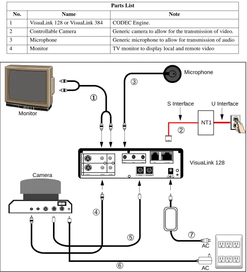
4.2.1 VisuaLink Standalone
Figure 4-1: Connection Diagram for VisuaLink 128
Parts List
No. Name Note
1 VisuaLink 128 or VisuaLink 384 CODEC Engine.
2 Controllable Camera Generic camera to allow for the transmission of video. 3 Microphone Generic microphone to allow for transmission of audio
4 Monitor TV monitor to display local and remote video
+
+
+ +
+ DC IN 5V
+ Serial1 Serial2/RMT O
U T
I N
VIDEO2 VIDEO1 AUDIO
+ +
TEL S/T LINE MIC1 MIC2 MIC3
➅
➆
➃
➂
①
➄
AC VisuaLink 128 Camera Monitor➁
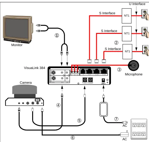
AC Microphone NT1Figure 4-2: Connection Diagram for VisuaLink 384
➅
➆
➃
➂
①
➄
AC VisuaLink 384 Camera Monitor➁
AC + + + + + DC IN 5V+ Serial1 Serial2/RMT O
U T
I N
VIDEO2 VIDEO1 AUDIO
+ +
TEL S/T LINE 1 S/T LINE 2 S/T LINE 3 MIC1 MIC2 MIC3
NT1 NT1 NT1 Microphone S Interface S Interface S Interface U Interface
Connection Procedure
① ~ ➆ indicate the procedure numbers.
① Connect the Video Out and the audio of the VisuaLink to the Video Monitor
Using the attached video cable, plug one side into the connection marked VIDEO 1 IN on the Video Monitor. Plug the other end into the connection marked VIDEO OUT on the VisuaLink. Using the provided audio cable, plug one end into the AUDIO INPUT 1 of the Video Monitor. Plug the other end into the AUDIO OUTPUT of the VisuaLink.
Note: If a Voicepoint is used do not connect the audio output connection.
➁ Connect the NT1 device to the VisuaLink.
Using the provided data cable (RJ45 - RJ45), plug one end into the VisuaLink connection labeled ST/LINE. The other end of the cable, plugs into the NT1 device.
Note: If the NT1 device is located more than 300 feet (91 meters) away from the VisuaLink, set the NT1 to have a resistance of 100 Ω. This step must be repeated three (3) times for a VisuaLink 384. NT1 does not need to be installed if network terminates in a PBX. In this case connect ST/LINE directly into wall jack.
➂ Connect a microphone to the VisuaLink.
Plug the 3 1/2 mini connector into the VisuaLink connection marked MIC1. ➃ Connect the Video Camera to the VisuaLink.
Using the provided video cable, plug one end into the connection marked VIDEO IN on the D30 camera. Plug the other end of the video cable into the VisuaLink connection labeled VIDEO IN 1.
➄ Connect the camera control to the VisuaLink.
With a 8 pin minidin to 8 pin minidin, plug one end into the D30 camera connection marked VISCA IN. Plug the other end into the VisuaLink connection marked SERIAL 1.
➅ Connect the camera power.
Plug the Camera AC Power to the AC Power Strip at the bottom of the cabinet.
➆ Connect the VisuaLink AC Power.
4.2.2 VisuaLink with Voicepoint+
Figure 4-3: Connection Diagram for VisuaLink 128
Parts List
No. Name Note
1 VisuaLink 128 or VisuaLink 384
CODEC Engine.
2 Voice Point+ AEC-50 (option), A generic hands-free phone in the market works OK. 3 Serial Control Camera Generic camera to allow for the transmission of video.
4 TV monitor A generic monitor with a video and audio input.
+
+
+ +
+
DC IN 5V + Serial1 Serial2/RMT O
U T
I N
VIDEO2 VIDEO1 AUDIO
+
+ MIC1 MIC2 MIC3 TEL S/T LINE
➄
➃
➂
①
➅
AC AC VisuaLink 128 Camera Monitor VoicePoint➁
VideoAudio S Video IN VISCA OUT
Figure 4-4: Connection Diagram for VisuaLink 384
➅
➃
➂
①
➄
AC AC VisuaLink 384 Camera Monitor VoicePoint➁
VideoAudio S Video IN VISCA OUT
Power ON OFF MIC
➆
AC POWER STRIP PC Terminal➇
➈
+ + + + + DC IN 5V+ Serial1 Serial2/RMT O
U T
I N
VIDEO2 VIDEO1 AUDIO
+ +
TEL S/T LINE 1 S/T LINE 2 S/T LINE 3 MIC1 MIC2 MIC3
NT1 NT1 NT1 S Interface S Interface S Interface U Interface
Connection Procedure
① ~ ➉ indicate the procedure numbers.
① Connect the Video Out of the VisuaLink to the TV Monitor
Using the attached video cable, plug one side into the connection marked VIDEO 1 IN on the TV Monitor. Plug the other end into the connection marked VIDEO OUT on the VisuaLink.
➁ Connect audio from the VisuaLink to the TV Monitor.
Using the provided audio cable, plug one end into the AUDIO INPUT 1 of the TV Monitor. Plug the other end into the AUDIO OUTPUT of the VisuaLink.
Note: If a Voicepoint is used do not connect the audio output connection.
➂ Connect the Voicepoint to the VisuaLink.
Using the attached RJ11 cable of the Voicepoint, plug the open end into the VisuaLink connection labeled TEL.
④ Connect the NT1 device to the VisuaLink.
Using the provided data cable (RJ45 - RJ45), plug one end into the VisuaLink connection labeled ST/LINE. The other end of the cable, plugs into the NT1 device.
Note: If the NT1 device is located more than 300 feet (91 meters) away from the VisuaLink, set the NT1 to have a resistance of 100 Ω. This step must be repeated three (3) times for a VisuaLink 384. NT1 does not need to be installed if network terminates in a PBX. In this case connect ST/LINE directly into wall jack.
➄ Connect the Video Camera to the VisuaLink.
Using the provided video cable, plug one end into the connection marked VIDEO IN on the D30 camera. Plug the other end of the video cable into the VisuaLink connection labeled VIDEO IN 1.
⑥ Connect the camera control to the VisuaLink.
With a 8 pin minidin to 8 pin minidin, plug one end into the D30 camera connection marked VISC IN. Plug the other end into the VisuaLink connection marked SERIAL 1.
➆ Connect the camera power.
Plug the Camera AC Power to the AC Power Strip at the bottom of the cabinet.
➇ Connect a PC to the VisuaLink for data sharing.
➈ Connect the VisuaLink AC Power.
Using the provided AC transformer power cable, plug the power cable into the VisuaLink connection marked DC-IN-5V. Plug the other end into the AC POWER STRIP.
4.2.3 Desktop Configuration
Step-by-step procedures for installating the VisuaLink system in a desktop application.
Equipment to Connect
Parts List
No. Name Note
1 VisuaLink 128 or VisuaLink 384 CODEC Engine.
2 Microphone Generic Microphone to allow for the transmission of audio.
3 Stand-type Camera Generic camera to allow for the transmission of video. 4 PC (Provided by customer) Your personal PC with a monitor. PC should have
audio input capability.
5 Video Capture Card Allows for the input of a video image into a PC. 6 Director Software Allows for VisuaLink control via PC. Software may be
downloaded from Web site:
http://www.cng.nec.com/html/products.htm
1. Click on the NTAC icon or select SUPPORT from the menu bar at the top of the screen.
2. At the CNG SUPPORT screen, click on the NTAC Online text.
3. At the National Technical Assistance Center screen, click on the Downloads
icon or the Downloads text on the menu bar.
4. At the Downloads screen, click on the Arrow icon at the top or bottom of the screen until you come to Video-VL128/384.
5. Click on the , then click of the VisuaLink Director for VL128/VL384 text that is highlighted in blue.
Note: If you have a problem with this procedure, please call the NTAC support line at 1-800-852-4632.
▲
Figure 4-5: Connection Diagram for VisuaLink 128 +
+
+ +
+
DC IN 5V + Serial1 Serial2/RMT O
U T
I N
VIDEO2 VIDEO1 AUDIO
+
+ MIC1 MIC2 MIC3 TEL S/T LINE
AC AC VisuaLink 128 AC POWER STRIP Microphone PC Terminal PC Camera AC
Video Capture Card
RS-232C (COM1) U Interface S Interface AC V i d e o O u t A u d i o O u t Video In Audio In Amplified Speakers (Optional)
NT1
COM Port 2
VIDEO DC IN 6V
COM Port 1
VGA Port
Note1: PC backpanel may be different than the one shown. Reference the PC manual and Capture card for location of connectors.
Figure 4-6: Connection Diagram for VisuaLink 384 NT1 + + + + + DC IN 5V
+ Serial1 Serial2/RMT O
U T
I N
VIDEO2 VIDEO1 AUDIO
+ +
TEL S/T LINE 1 S/T LINE 2 S/T LINE 3 MIC1 MIC2 MIC3
AC AC VisuaLink 384 AC POWER STRIP Microphone PC Terminal PC Camera AC
Video Capture Card
RS-232C (COM1) U Interface S Interface AC V i d e o O u t A u d i o O u t Video In Audio In
Amplified Speakers (Optional)
NT1 NT1
COM Port 2
VIDEO DC IN 6V
COM Port 1
VGA Port
Note 1: PC backpanel may be different than the one shown. Reference the PC manual and Capture card for location of connectors.
Connection Procedure for VisuaLink 128 and VisuaLink 384
1. Install the video capture card into the PC.
Procedure for installing video capture card are included with unit. 2. Position of the VisuaLink on desk top.
Place the VisuaLink on the desk top beside the PC. 3. Position of the PC
Center the PC on the top of the table. 4. Position of the camera
Center the camera on top or next to the PC monitor. Using the two (2) provided Velcro strips, attached the camera to the top of the PC monitor. 5. Position and connect the NT1 device
Position the NT1 to the left of the VisuaLink on the table top. Connect the cable to the NT1 S/T interface and to the VisuaLink ST/LINE interface. Note: If the NT1 device is located more than 300 feet (91 meters) away from
the VisuaLink, it is best to use the 1 foot (0.3 meter) adapter cable and set the NT1 to have a resistance of 100Ω. This step must be repeated three (3) times for a VisuaLink 384. NT1 does not need to be installed if network terminates in a PBX. In this case connect ST/LINE directly into WALL JACK.
6. Connect the audio, video and control cables
Locate the cable bundle. The bundle should contain four (4) cables tie-wrapped together. Each cable is labeled according to its connector. This label identifies the cable connection to the proper equipment interfaces.
7. Connect the peripheral equipment to the power strip The power strip is located on the floor behind the table.
An AC adapter has different output voltage and current depending on how it is used. Please use the power adapter that is shipped with your unit. Also, if incorrectly connected, it may damage the equipment.
VIDEO
4.2.4 Rollabout Configuration
Step by step procedure for installing the VisuaLink system in a turnkey rollabout.
Figure 4-7: Equipment Placement
1 2 VIDEO IN S-VIDEO VIDEO AUDIO L MONO R AUDIO OUT (VAR/FIX) 1 2 VIDEO IN S-VIDEO VIDEO AUDIO L MONO R AUDIO OUT (VAR/FIX) + + + + +
DC IN 5V + Serial1 Serial2/RMT O
U T
I N
VIDEO2 VIDEO1 AUDIO
+
+ MIC1 MIC2 MIC3 TEL S/T LINE AUDIO VIDEOS VIDEO IN VISCA OUT
POWER OFF ON DC IN 13.5 V + -MIC CAMERA NO.
1 2 3
CAMERA REAR
MONITOR REAR
VisuaLink 128 REAR
NT1 REAR
VHF/UHF
S/T S/T
L-BK LINE PWR DIN INTERFACE
1 2 3 4 5
ON POWER U NT1 FRONT + + + + + DC IN 5V
+ Serial1 Serial2/RMT O
U T
I N
VIDEO2 VIDEO1 AUDIO
+ +
TEL S/T LINE 1 S/T LINE 2 S/T LINE 3 MIC1 MIC2 MIC3
VisuaLink 384 REAR
Note: Connector location on
the monitor may vary. Note: Labeling for the connector may vary.
Control,Video, & Audio Hole
4.2.5 VisuaLink System Procedures
The following are the steps and procedures for the installation of the VisuaLink 128 or VisuaLink 384.
STEP ACTION DRAWING
1. Locate and unpack the Cabinet box.
2. Locate Power Strip at botton-left (looking through the front) of cabinet and feed power cable through the power opening at rear of cabinet.
3. Plug power strip power cable into AC outlet. Make sure the ON/OFF switch on the upper right outside of the cabinet is in the OFF position. Note: The power switch will be lite when in the
ON position.
Powerstrip
4. Remove Monitor from monitor box.
4a. Place TV monitor on top of cabinet.
5. Locate monitor power cable and feed through the cable opening at the top of cabinet.
6. From inside the cabinet, plug the monitor power cable into power strip.
STEP ACTION DRAWING
12 VIDEO IN S-VIDEO
VIDEO AUDIO L MONO
R AUDIO OUT(VAR/FIX)
Power Cable
7. Locate the cable bundle and remove from packing box. The cable bundle contains two (2) 5 in. (12 cm.) Velcro strips. Use these strips to mount the camera to the top of the monitor.
8. Locate the camera box and remove camera.
9. Set the IR switch on the Sony D30 camera to the ON position. The IR switch is located on the bottom of the Sony D30 camera. This will allow for the Sony Camera to receive the IR codes from the VisuaLink remote controller and transmit them to the VisuaLink Codec for control.
Mount the camera on the top of monitor, using the Velcro strips. Make sure the front of the camera is flush with the front of the monitor and the camera is centered.
STEP ACTION DRAWING
Foam Inserts
Polyethylene Bag
Packing Carton
Velcro Strips
10. Locate the camera power cable. Plug the camera power cable into the power strip in cabinet, then feed cable through top of cabinet and plug into the rear of the camera.
11. Locate the VisuaLink 128 or VisuaLink 384 and remove from packing box.
12. Place the VisuaLink 128 or VisuaLink 384 on the second shelf of the cabinet.
STEP ACTION DRAWING
12 VIDEO IN S-VIDEO
VIDEO AUDIO L MONO
R AUDIO OUT(VAR/FIX)
Video Power Cable
Power Cable Hole
Polyethylene Bag
Foam Inserts
Packing Carton
13. Locate the VisuaLink 128 or VisuaLink 384 power cable. Plug cable into power strip at bottom of cabinet and feed cable through cable slot in rear of second shelf. Plug second end of power cable into power input at rear of the VisuaLink 128 or VisuaLink384.
14. The cable bundle is labeled at the ends of the various connectors. Plug these connectors into the appropriate devices (camera/monitor) and feed down through opening at top of cabinet. See Figure 4-1 and Figure 4-2.
Note: Connector layout could vary by manufacture. Please consult their documentation if connector layout is different.
STEP ACTION DRAWING
Power Plug Connection
+
+
+ +
+
DC IN 5V
+ Serial1 Serial2/RMT O
U T
I N
VIDEO2 VIDEO1 AUDIO
+
+ MIC1 MIC2 MIC3 TEL S/T LINE
VisuaLink 128 Rear
+
+
+ +
+ DC IN 5V
+ Serial1 Serial2/RMT O
U T
I N
VIDEO2 VIDEO1 AUDIO
+ +
TEL S/T LINE 1 S/T LINE 2 S/T LINE 3 MIC1 MIC2 MIC3
VisuaLink 384 Rear
Power Plug Connection
VISCA In 1 2 VIDEO IN S-VIDEO VIDEO AUDIO L MONO R AUDIO OUT (VAR/FIX) Camera Control Sony D30 Camera Vout CAMERA MONITOR VHF/UHF Monitor Vin
Monitor Audio L (Cable)
15. Inside the cabinet, connect the other ends of the cable bundle to the VisuaLink 128 or VisuaLink 384. See Figure 4-1 and Figure 4-2.
16. Locate and unpack the microphone and connect the 3 1/2 inch plug into the VisuaLink connection marked MIC1. String the MIC cable out of the rear of the cabinet. Connect the other end of the cable into the Microphone and place on table.
STEP ACTION DRAWING
+
+
+ +
+
DC IN 5V
+ Serial1 Serial2/RMT O
U T
I N
VIDEO2 VIDEO1 AUDIO
+
+ MIC1 MIC2 MIC3 TEL S/T LINE
Serial 1 VisuaLink 128/384
(Cable) Video In
(Cable)
VisuaLink 128 Rear Video Out
(Cable) Audio Output(Cable)
+
+
+ +
+ DC IN 5V
+ Serial1 Serial2/RMT O
U T
I N
VIDEO2 VIDEO1 AUDIO
+ +
TEL S/T LINE 1 S/T LINE 2 S/T LINE 3 MIC1 MIC2 MIC3
VisuaLink 384 Rear Video Out
(Cable) Audio Output (Cable) Serial 1 (Cable) VisuaLink 128/384 Video In (Cable) + + + + +
DC IN 5V
+ Serial1 Serial2/RMT O
U T
I N
VIDEO2 VIDEO1 AUDIO
+
+ MIC1 MIC2 MIC3 TEL S/T LINE
MIC1
+
+
+ +
+ DC IN 5V
+ Serial1 Serial2/RMT O
U T
I N
VIDEO2 VIDEO1 AUDIO
+ +
TEL S/T LINE 1 S/T LINE 2 S/T LINE 3 MIC1 MIC2 MIC3
VisuaLink 384 Rear VisuaLink 128 Rear
17. If an NT1 device has been purchased, locate the device and unpack.
Note 1: If an NT1 was not purchased go to Step 23.
Note 2: Three NT1 are used for the VL384.
18. Locate the dip switch on the rear of the NT1 and set all to the ON position.
19. Place the NT1 or the three NT1s on the second shelf, to the right of the VisuaLink 128 or VisuaLink 384.
20. Locate the NT1 power cable. Plug cable into power strip at bottom of cabinet and feed cable through cable slot in rear of second shelf. Plug second end of power cable into power input at rear of the NT1.
STEP ACTION DRAWING
Polyethylene Bag
Foam Inserts
Packing Carton
1 2 3 4 5
ON
1 2 3 4 5
ON
POWER U
NT1 REAR
POWER HEADSET POWERLINEB1 B2
NT1
VisuaLink 128/384 (one for 128)
(three for 384)
1 2 3 4 5
ON
POWER U
21. Locate the network cable (RJ45-RJ45) and connect one end to the S/T LINE port of the VisuaLink 128 or VisuaLink 384. Connect the other end of the network cable into the S/T interface of the NT1.
Note: RJ45-RJ45 cable that is included with the NT1 unit should be used.
22. Connect the network cable from the U interface on the NT1 to the network jack provided on the room wall. Proceed to Step 24.
Note 1: RJ45-RJ45 cable that is included with the NT1 unit should be used.
Note 2: If connecting a VisuaLink 384 system, Step 21 will have to be repeated three (3) times.
STEP ACTION DRAWING
+
+
+ +
+
DC IN 5V
+ Serial1 Serial2/RMT O
U T
I N
VIDEO2 VIDEO1 AUDIO
+
+ MIC1 MIC2 MIC3 TEL S/T LINE
RJ45 NT1 Cable
S/T S/T
L-BK LINE PWR DIN
INTERFACE
ST Interfaces
VisuaLink 128 Rear
NT1 Front
+
+
+ +
+ DC IN 5V
+ Serial1 Serial2/RMT O
U T
I N
VIDEO2 VIDEO1 AUDIO
+ +
TEL S/T LINE 1 S/T LINE 2 S/T LINE 3 MIC1 MIC2 MIC3
VisuaLink 384 Rear RJ45 NT1 Cable
1 2 3 4 5
ON
POWER
U
NT1 Rear
23. Locate the network cable (RJ45-RJ45) and connect one end to the S/T LINE port of the VisuaLink 128 or VisuaLink 384. Connect the other end of the network cable into the network interface provided in the room wall.
Note 1: If the NT1 or network switch resides 300 feet (91 meters) or more away from the VisuaLink 128 or VisuaLink 384, it is recommended that the TERM switch is set to ON on the VL128.
Note 2: In the case a VL384 is being installed, the network interface card must be taken out of the system and the appropriate strap must be set.
Note 3: If the VL 384 is being installed, Step 23 must be repeated three (3) times.
24. Locate the ON/OFF switch at the upper right outside of the cabinet. Press the switch to the ON position.
STEP ACTION DRAWING
+
+
+ +
+
DC IN 5V
+ Serial1 Serial2/RMT O
U T
I N
VIDEO2 VIDEO1 AUDIO
+
+ MIC1 MIC2 MIC3 TEL S/T LINE
RJ45 NT1 Cable
+
+
+ +
+ DC IN 5V
+ Serial1 Serial2/RMT O
U T
I N
VIDEO2 VIDEO1 AUDIO
+ +
TEL S/T LINE 1 S/T LINE 2 S/T LINE 3 MIC1 MIC2 MIC3
VisuaLink 384 Rear RJ45 NT1 Cable VisuaLink 128 Rear
25. Verify that all the equipment plugged into the power strip are turned to the ON position. The VisuaLink 128, VisuaLink 384, camera and monitor have their own power switches. If a device appears to be still in the OFF position, check the power connection from the Power Strip to the device. The NT1 does not have a power switch. The green LED on the front of the NT1 is an indication the unit is powered ON.
Note: Make sure the monitor is selected for Video 1.
26. When the VisuaLink 128 or VisuaLink 384 is powered ON, a display of the NEC America, Inc logo, VisuaLink name, POWERING UP and version number will be displayed on the monitor.
STEP ACTION DRAWING
POWER HEADSET POWERLINEB1 B2 Powering Up
Ver.22.02.37
VisuaLink
4.3 Software Setup When you first turn on your VisuaLink, there will be an initial configuration screen. These configuration screens will have to be completed before your system becomes operational.
Start up configuration screens
The following are the startup screens that will be active on first power up or acti-vated on demand by the user after choosing the Environmental initialize.
Welcome Screen:
This is a welcome screen for the User.
VisuaLink
Thank you for purchasing one of the most simple and portable video conferencing systems available.
We will now show you how to set up your system. This will only have to be done once.
NOTE: If remote controller doesn’t work, make sure the switch setting of D30 camera IR out is ON. Switch is located on the bottom of the camera.
Click here to continue Configure later
▲
Remote Controller Directions:
Gives some general directions for configure the VisuaLink system. Using the Remote controller highlight the NEXT option to advance to the configure screen or press the lower portion of the CAMERA CONTROL key to highlight the Configure Later to advance to the normal ICON screens. If you choose to configure later, the system will have to be programmed with My numbers and SPID’s in order to work correctly.
4.4 Setting Up your ISDN Line Information
The following is a description of BRI Line setup Part 1- Remote Controller Location
- Locate the CAMERA control.
The CAMERA control key is the BLUE round key. Use this key to move the Cursor
up/down and Left/Right in the Configuration Screens.
- Locate the ENTER key on the Wireless remote controller.
Use the ENTER key to confirm selections and store information.
Next screen Prior screen
▲
Part 2- Setting up Your ISDN Line Introduction:
When ordering BRI service, you will usually get 2 My numbers and 2 SPID numbers per BRI. A SPID normally consists of the user’s 3 digit area code, 7 digit ISDN telephone number, followed by a 0101. Ex:
MY Number 1: 9727195854 SPID 1: 97271958540101
Note: The VisuaLink 128 requires 2 My numbers and 2 SPID #, while the VisuaLink 384 requires 6 My numbers and 6 SPID #.
Next screen Prior screen
▲
Video Number 1 Screen’s
Using the number pad of the wireless remote enter My Number with area code and SPID numbers associated to Line (BRI 1). Each BRI will have My numbers labeled #1 and #2 and two SPID’s . All four numbers must be entered. Choose NEXT when complete.
Note: “PROCEED TO STEP 2” will only be shown on the VisuaLink 128 system. VisuaLink 384 will show “ Proceed to Line 2 Setup”
Step 1--Enter My Number and SPID for BRI LINE 1
My Number 1:
[ ]
SPID 1:
[ ]
My Number 2:
[ ]
SPID 2:
[ ]
Next screen Prior screen
Press ENTER after choosing each item
▲
Step 1--Enter My Number and SPID for BRI LINE 1
My Number 1:
[9727195854] SPID 1:
[97271958540101] My Number 2:
[9727195855] SPID 2:
[ ]
Next screen Prior screen
Press ENTER after choosing each item
Video Number 2 Screens:
Using the number pad of the wireless remote enter My Number with area code and SPID numbers associated to Line (BRI 2). Each BRI will have My numbers labeled #1 and #2 and two SPID’s . All four numbers must be entered. Choose NEXT when complete.
Note: This screen will only appear on the VL 384 system.
Step 1--Enter My Number and SPID for BRI LINE 2
My Number 1:
[ ]
SPID 1:
[ ]
My Number 2:
[ ]
SPID 2:
[ ]
Next screen Prior screen
Press ENTER after choosing each item
Video Number 3 Screens:
Using the number pad of the wireless remote enter My Number with area code and SPID numbers associated to Line (BRI 3). Each BRI will have My numbers labeled #1 and #2 and two SPID’s . All four numbers must be entered . Choose NEXT when complete.
Note: This screen will only appear on the VL 384 system.
4.5 Optional User Settings:
The following is a description for Optional Setting screen. Step 1--Enter My Number and SPID for BRI LINE 3
My Number 1:
[ ]
SPID 1:
[ ]
My Number 2:
[ ]
SPID 2:
[ ]
Next screen Prior screen
Press ENTER after choosing each item
▲
Part 3 - Optional User Settings Introduction:
Site Name: Name identification for your location. Name is displayed on far-end monitor when site is viewed. Password: Required to gain access to the
VisuaLink configuration screens.
Time setting: Sets the internal clock for the VisuaLink.
Next screen Prior screen
Optional information:
You may enter this optional information. The name you enter makes it easy for users to identify this particular VisuaLink. The name can be up to 20 characters long. The Password is the password needed to be entered when selecting the Utilities ICON. After entering the optional information select the NEXT to advance to the next screen.
Application Screen’s
Using the number pad on the wireless remote controller select the application which the VisuaLink is installed. Your answer to this question will automatically configure the internal parameters for the following:
Step 1- Optional User Settings
Your Site Name [ ] Password [ ]
Time Setting [12/1/1998 10:50]
Time Display: <Time only> Auto Power Save: <OFF> Next screen
Prior screen
Press ENTER after choosing each item
▲
Item Rollabout/Other Data Conference Gateway Desktop
Serial Port 1 Camera EVI-D30 T.120 Camera Camera
Serial Port 2 Console Console Console Console
Audio Mode G.722 G.728 G.722 G.722
MLP 4.0 24.0 4.0 4.0
Answer Mode Auto Auto Auto Manual
LSD 1.2 Off 1.2 1.2
Ext. Remote Auto Off Off Off
H.263 Off Off Off Off
Congratulations Screen
The VisuaLink is now setup for the configuration you have entered. Press the ENTER button on the REMOTE CONTROLLER, the VisuaLink will display a blue screen and recycle. The VisuaLink should will power up to a normal state. You may begin to use the video conferencing system immediately.
Note: If there are no My Numbers entered in the configuration the VisuaLink will display the Start Up screens.
Step 2—Optional User Settings Key in the number of one of the following applications.
Applications:
1. Rollabout/Other 2. Data Conference 3. Gateway 4. Desktop
Press CANCEL to page back
Congratulations, you have just finished setting up your VisuaLink system.
For VisuaLink software updates and general VisuaLink knowledge, visit the NEC Knowledge base web site at :
http://www.cng.nec.com or
http://www.ilibrary.com/phoenix/ntachome.nsf /homepagenav?opennavigator
- You may begin to use the video conferencing system immediately.
Powering Up Screen
Changing the configuration
It is important that the CODEC is set up with a local number and SPID numbers. If the unit is not setup with a local number (my number) and SPID, the unit will not allow for dialing and receiving of video calls. If you have entered these numbers in the Start Up configuration, you may ignore this section. If the VisuaLink environment has changed, such as the phone number have changed, you must reconfigures the numbers in the VisuaLink.
America, Inc.
VisuaLink
Powering Up
Chapter 5 System Parameter/Environment Setting
System parameter sets the operation conditions of the VisuaLink 128 or VisuaLink 384. Environment setting can be set such as camera class, audio related, data related, line related and local office status. Loopback feature can be used as a maintenance feature.
Note 1: Make system parameter changes when the system is not connected.
Note 2: Depending on the setting for audio, data speed and bit rate, and the video has the possibility for not being transmitted. Please refer to Appendix A:
Audio/Data/Video Bit Rate Assignment Table for bit rate assignment of
audio, data, video bit rate.
5.1 Environment Setting Menu
5.1.1 Set an environment
① Press the MENU button to display the MAIN MENU.
▲
Setting the PIP parameter.
➁ Move the cursor with the CAMERA CONTROL button to the ENVIRONMENT SETTING icon.
➂ Press the ENTER button.
The system will not operate correctly if the environment setting are incorrect. Therefore, the system has a password so that only the person in charge of
controlling video conference can change the settings. Factory default password is 1234.
▲ Setting environments.
CAMERA CONTROL
Please input password.
[ ]
Press ENTER after inputting password.
➃ Enter the password.
A password consists of 4-digit number. Input characters are displayed in *. Please input password.
[****]
Press ENTER after inputting password.
➄ Press the ENTER button.
When a password is correctly entered: Environment setting menu is displayed.
You can choose an icon with the CAMERA CONTROL button.
ENTER
▲
Video parameter setting.
CAMERA CONTROL
Icon Description
Menu icon for setting video algorithms, video coding, video priorities, camera control, and video input selection
Menu icon for setting audio algorithms, audio delay, audio input/output port assignments, and voice activated camera control.
Menu icon for activating data speed and serial control.
Menu icon for setting video speed, network numbers, and call answer mode.
Menu icon for setting the site name, my number, password, and SPIDs.
Menu icon for activating loopbacks, also allows for the viewing of
5.1.2 When a password is incorrect
It goes back to the password-entering screen.
Note: Press the CANCEL button to get out of the menu. Please input password.
[ ]
Password incorrect.
Press ENTER after inputting password.
5.2 Video Setting This sets video, algorithm, types of camera to be controlled, and video input selection.
To set video
① Select VIDEO SETTING icon in the environment setting menu.
➁ Press ENTER button.
ENTER
▲
Video parameter setting.
The setting screen is displayed. The current setting is displayed.
Note 1: To select an item use the up and down portion of the CAMERA CONTROL button.
Note 2: To change a setting use the left and right portion of the CAMERA CONTROL button to toggle through the item.
➂ Press ENTER button to define it after changing a setting.
Note: After changing a setting, please turn off the power and on again.
➃ Press the MENU or CANCEL button three (3) times to proceed back to the video image.
ENTER
Video format : < FCIF> Video coding : < H263 > Video priority : < Motion > Camera type : < EVI-D30 > Video source
VIDEO1 : < Camera1 > VIDEO2 : < Camera2 > MUTE function : <Audio and Video>
Press ENTER after choosing.
▲
CAMERA CONTROL
Video format: Sets the video format. Possible settings are: FCIF:352 x 288 or QCIF:176 x 144
Video Coding: Sets the default coding rate. Possible settings are: H.261 or H.263
Video priority: Sets the default video coding transmission rate. Possible settings are:
Motion: more of the bandwidth dedicated toward fps.
Resolution: more of the bandwidth dedicated toward resolution. Camera mod: Sets the type of camera to be controlled. Possible settings are:
EVI-D30 or VC-CI
Video 1 and 2: Operate together. Sets which of the video inputs labeled on the back of the VisuaLink are to be camera 1 or 2.
5.3 Audio Setting This icon sets the audio algorithm, audio delay, audio input/output port assignment, and voice activation camera control.
To set audio:
① Select audio setting icon in the environment setting menu.
➁ Press ENTER button.
ENTER
▲
Audio Parameter Setting.
CAMERA
The setting screen is displayed. The current setting is displayed.
Note 1: To select an item use the up and down portion of the CAMERA CONTROL button.
Note 2: To change a setting use the left and right portion of the CAMERA CONTROL button to toggle through the item.
Audio mode : < SB-ADPCM > Audio delay : < ON > Audio in/out port : < AUTO > VCR play : <OFF > Voice tracking : < ON > Echo canceller : < ON > Mute auto answered calls : < No >
Audio level adjustment: CALL PAGE Press ENTER after choosing.
Audio mode: Sets the default audio coding. Possible settings are: SB-ADPCM (7kHz, 48 ~ 56kbps), µlaw PCM (3.5kHz, 56kbps), LD-CELP (3.5kHz, 16kbps) or OFF.
Audio delay: Sets the audio transmission/reception delay. This allow lip sync.
Audio in/out port: Sets the audio in and out port. Possible settings are: Auto: The VisuaLink determines which output is
connected and input/output from the appropriate connector.
Line: The input and output audio from the line level port labeled audio in/out on the back. Headset: The input and output audio from the headset
connection on the front.
Telephone: The input and output audio from the telephone connection on the back.
VCR play: Sets the audio input port to receive a VCR audio signal. Voice tracking: Sets the voice activated presets on or off.
Echo canceller: Sets the echo canceller to internal or external mode. Mute auto answered
calls:
Sets the audio to be mute or unmute at the start of communication in an automatic answer mode.
➂ Press the CALLPAGE button to proceed to the AUDIO LEVEL PAGE.
➃ Press ENTER button to define it after changing a setting.
➄ Press the MENU or CANCEL button three (3) times to proceed back to the video image.
-36 -30 -24 -18 -12 -6 0 +6 [dB]
SEND: RECEIVE:
MIC/headset gain : <04> Audio/TEL gain : <00> Volume:<08> Operation: Test Tone : <STOP> Training:
Camera Moving
Level: <3> Condition: _ _ _
Previous page: CALL PAGE
Please select an item and adjust with <–>.
Level bar for incoming and outgoing audio
Sets the outgoing audio level for the headset and MIC
Sets the outgoing audio level for the telephone and audio input
Status message for audio test tone
Status bar for the microphone:
1 2 3
MIC1 MIC2 MIC3 Sets the default volume
setting
Allows for activating or deactivating audio tone
Camera audio preset level