Features & Specifications
Manual
NEC Business Solutions Ltd
Document No.: 8201ii Features & Specifications Manual
A6-3240
00-642-01 - R
elea
se 1.0
Ju
ly 2003
Doc.
No. 8201
Release 1.0
July 2003
Preface & Disclaimer
GENERAL
INFORMATION
The Xen IPK System is a feature-rich key system that provides over 200 features including Computer Telephony Integration, Least Cost Routing, Automatic Call Distribution, ISDN Trunks and many others.
The Xen IPK system meets customer needs today and as business expands the system can be expanded to grow as well.
The Xen IPK system has a set of manuals that provide all the information necessary to install and support the system. The manuals are described in this preface.
THIS MANUAL
This manual provides specific detailed information and specifications for all features provided with the Xen IPK system for Australia.SUPPORTING
DOCUMENTS
Xen IPK General Description Manual
This Manual provides general information about the system, its features, system configuration and standards. This manual provides an overview of the Xen IPK System and can be used to present information to potential customers.
Xen IPK System Hardware Manual
The System Hardware Manual is provided for the system installer. This manual has detailed instructions for installing the Xen IPK system KSUs, ETUs, Multiline Terminals, and optional equipment.
Xen IPK System Programming Manual
This manual provides instructions for programming the Xen IPK and Axis system via a Multiline Terminal or PC.
Xen IPK Least Cost Routing Manual
This manual provides instructions to the service technician for programming the customer site for least cost routing.
Xen IPK Automatic Call Distribution Manual
iv Preface & Disclaimer
Doc. No. 8
201 - Re
lease 1.0
July 2003
NEC shall not be liable for any direct, indirect, consequential or incidental damages about the use of this equipment, manual or any related materials. The information in this technical manual is advisory in nature and is subject to change. NEC may make improvements and changes in the products described in this manual without notice. Changes will be periodically made to the information in the new editions.
Efforts have been made to ensure that the contents of this manual are correct. Should you find any error, NEC welcomes your comments to improve our communications, please contact NEC on 1800 036 136.
Contents of this manual are subject to change without prior notice at the discretion of NEC Business Solutions Ltd.
This document has been prepared for the use of employees and customers of NEC Business Solutions Ltd and may not be reproduced without the prior, written approval of NEC Business Solutions Ltd.
Copyright 2003
NEC Business Solutions Ltd 635 Ferntree Gully Road
Doc.
No. 8201
Release 1.0
July 2003
Table of Contents
Chapter 1 Regulatory Information . . . .1
SECTION 1 Electromagnetic Interference (EMI) . . . 1
SECTION 2 Incidence of Harm . . . 1
SECTION 3 Hearing Aid Compatibility . . . 1
SECTION 4 Service Requirements . . . 1
SECTION 5 Compliance Information. . . 2
SECTION 6 Voice Announcement/Monitoring. . . 2
SECTION 7 Music on Hold . . . 2
SECTION 8 UL Regulatory Information. . . 2
SECTION 9 Battery Disposal . . . 3
Chapter 2 Introduction . . . .5
SECTION 1 General Information. . . 5
SECTION 2 Multiline Terminals Used With The System. . . 5
Chapter 3 Features . . . .9
SECTION 1 General Information. . . 9
SECTION 2 Operating Procedures . . . 10
SECTION 3 Features . . . 10
A-1 Account Code Entry . . . 11
A-2 Account Code - Forced/Unverified . . . 15
A-3 Account Code - Forced/Verified . . . 19
A-4 Add-On Conference . . . 23
A-5 All Call Page . . . 25
A-6 Alphanumeric Display . . . 29
A-7 Ancillary Device Connection . . . 33
A-8 Answer Hold . . . 35
A-9 Answer Key . . . 37
A-10 Assigned Night Answer (ANA) . . . 39
vi Table of Contents
Doc. No. 8
201 - Re
lease 1.0
July 2003
A-12 Attendant Camp-On . . . 49
A-13 Attendant Positions . . . 53
A-14 Attendant Station Outgoing Lockout . . . 55
A-15 Attendant Transfer . . . 59
A-16 Authorisation Code . . . 61
A-17 Automatic Answer with Delay Message . . . 65
A-18 Automated Attendant . . . 71
A-19 Automatic Callback . . . 79
A-20 Automatic Call Distribution (ACD) . . . 81
A-21 Automatic Call Distribution (ACD Plus) . . . 87
A-22 Automatic Carrier Routing . . . 95
A-23 Automatic Day/Night Mode Switching . . . 99
A-24 Automatic Hold . . . 101
A-25 Automatic Redial . . . 103
A-26 Automatic Release . . . 107
A-27 Automatic Trunk-to-Trunk Transfer . . . 109
B-1 Background Music - Multiline Speaker . . . 113
B-2 Background Music Over External Speakers . . . 115
B-3 Barge-In . . . 117
B-4 Battery Backup - System Memory . . . 121
B-5 Battery Backup - System Power . . . 123
B-6 Busy Lamp Field on Multiline Terminals . . . 125
C-1 Call Alert Notification . . . 129
C-2 Call Appearance Keys (CAP) . . . 133
C-3 Call Arrival Keys (CAR) . . . 137
C-4 Callback Request . . . 141
C-5 Caller ID Call Return . . . 145
C-6 Caller ID - Incoming . . . 151
C-7 Caller ID - Outgoing . . . 157
C-8 Call Forward - All Calls . . . 161
C-9 Call Forward - Busy/No Answer . . . 167
C-10 Call Forward - Display . . . 171
C-11 Call Forward - Off-Premise . . . 173
C-12 Call Forward - Split . . . 179
C-13 Call Park - System . . . 183
C-14 Call Pickup Direct . . . 187
C-15 Call Pickup Group . . . 191
C-16 Centralised Voice Mail . . . 195
C-17 Class of Service . . . 201
C-18 Clock/Calendar Display . . . 207
Xen IPK Features and Specifications Manual
D
oc. N
o. 8201
Release
1.0
July 20
03
C-20 Code Restriction Password Override . . . 213
C-21 CO/PBX, Tie Line Digit Restriction . . . 217
C-22 Computer Telephony Integration (CTI) . . . 219
C-23 Consecutive Speed Dial . . . 221
C-24 Cordless Telephone Connection . . . 223
C-25 Customised Message . . . 227
D-1 Data Line Security . . . 231
D-2 Delay Announcement . . . 233
D-3 Delayed Ringing . . . 237
D-4 Dial 9 For Attendant . . . 239
D-5 Dialled Number Identification Service (DNIS) . . . 241
D-6 Digit Insertion . . . 245
D-7 Digital Voice Mail . . . 247
D-8 Direct Inward Dialling (DID) . . . 257
D-9 Direct Inward System Access (DISA) . . . 263
D-10 Direct Inward Termination (DIT) . . . 269
D-11 Direct Paging Access . . . 271
D-12 Direct Station Selection . . . 273
D-13 Distinctive Ringing . . . 275
D-14 Do Not Disturb (DND) . . . 279
D-15 Door Lock Release Relays . . . 283
D-16 Door/Monitor Telephone . . . 285
D-17 DP to DTMF Switching . . . 287
D-18 Drop Key . . . 289
D-19 Dterm Series i Multiline Terminals . . . 291
D-20 DTU-type Multiline Terminal Migration . . . 297
E-1 Elapsed Call Timer . . . 299
E-2 Electronic Volume Control . . . 301
E-3 E&M Tie Lines (4-Wire) . . . 305
E-4 Equal Access Accommodation . . . 309
E-5 External Tone Ringer . . . 311
E-6 External Zone Paging (Meet-Me) . . . 313
F-1 Feature Access – User Programmable . . . 317
F-2 Flexible Line Assignment . . . 321
F-3 Flexible Numbering Plan . . . 323
F-4 Flexible Ringing Assignment . . . 325
F-5 Flexible Timeouts . . . 327
F-6 Full Duplex Handsfree . . . 331
F-7 Full Handsfree Operation . . . 333
viii Table of Contents
Doc. No. 8
201 - Re
lease 1.0
July 2003
G-2 Group Listening . . . 337
H-1 Handset Mute . . . 339
H-2 Handsfree Answerback . . . 341
H-3 Handsfree Dialling and Monitoring . . . 343
H-4 Headset Connection (Built In) . . . 345
H-5 Hold With Recall (Exclusive & Non-Exclusive) . . . 347
H-6 Hot Line . . . 351
H-7 Howler Tone Service . . . 353
I-1 I-Hold Indication . . . 355
I-2 Incoming Call Identification . . . 357
I-3 Intercom By-Pass CO Call . . . 359
I-4 Internal Voice/Tone Signalling . . . 361
I-5 Intercom Function . . . 363
I-6 Internal Zone Paging (Meet Me) . . . 367
I-7 ISDN-BRI Trunk Connections . . . 371
I-8 ISDN-PRI Trunk Connections . . . 377
I-9 ISDN Supplementary Services . . . 385
I-10 I-Use Indication . . . 387
K-1 Key Function/Multifunction Registration . . . 389
L-1 Large LED Indication . . . 391
L-2 Last Number Redial . . . 393
L-3 Least Cost Routing (LCR) . . . 395
L-4 Live Monitoring . . . 399
L-5 Loop Start Trunks . . . 403
M-1 Message Waiting . . . 405
M-2 Microphone Control . . . 407
M-3 Multiline Conference Bridge . . . 411
M-4 Multilingual LCD Indication . . . 415
M-5 Multiple Trunk Groups . . . 417
M-6 Multi-Zone Digital Cordless . . . 419
M-7 Music on Hold . . . 427
N-1 Nesting Dial . . . 431
N-2 Night Call Pickup . . . 435
N-3 Night Chime . . . 437
N-4 Night Transfer . . . 439
O-1 Off-Hook Ringing . . . 443
O-2 Off-Premise Extension . . . 445
O-3 One-Touch/Feature Access Key . . . 447
P-1 PC Attendant Console . . . 449
P-2 PC Programming . . . 453
Xen IPK Features and Specifications Manual
D
oc. N
o. 8201
Release
1.0
July 20
03
P-4 Power Failure Transfer . . . 457
P-5 Preset Dialling . . . 459
P-6 Prime Line Assignment . . . 461
P-7 Privacy on All Calls . . . 463
P-8 Privacy Release . . . 465
P-9 Private Lines . . . 469
P-10 Programming from Multiline Terminal . . . 471
P-11 Push Button Dial - DTMF or DP . . . 473
Q-1 Quick Transfer to Voice Mail . . . 475
R-1 Recall Key . . . 479
R-2 Recall With Station Identification . . . 483
R-3 Redial Key . . . 485
R-4 Remote Programming . . . 487
R-5 Resident System Program . . . 489
R-6 Restriction (Outgoing) . . . 491
R-7 Ringing Line Preference . . . 493
R-8 Ring Tone Variation . . . 495
R-9 Route Advance Block . . . 497
S-1 Save and Repeat . . . 499
S-2 Scrolling Directories . . . 501
S-3 Secondary Incoming Extension . . . 505
S-4 Seized Trunk Name/Number Display . . . 507
S-5 Simplified Call Distribution . . . 509
S-6 Single Line Telephone Access . . . 511
S-7 SLT Adapter . . . 515
S-8 SLT Timed Alarm . . . 517
S-9 Softkeys . . . 519
S-10 Speed Dial – Station . . . 521
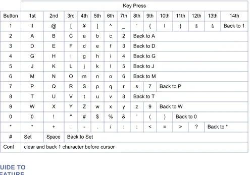
S-11 Speed Dial Stored Characters . . . 525
S-12 Speed Dial – System . . . 529
S-13 Station Camp-On . . . 533
S-14 Station Hunting . . . 535
S-15 Station Message Detail Recording (SMDR) . . . 539
S-16 Station Name/Number Display . . . 545
S-17 Station Outgoing Lockout . . . 547
S-18 Station Relocation . . . 551
S-19 Station Transfer . . . 555
S-20 Step Call . . . 557
S-21 Store and Repeat . . . 559
x Table of Contents
Doc. No. 8
201 - Re
lease 1.0
July 2003
S-23 Synchronous Ringing . . . 565
S-24 System Data Up/Down Load . . . 567
T-1 Tandem Switching of 4-Wire E&M Tie Lines . . . 569
T-2 Tenant Service . . . 573
T-3 Three-Minute Reminder . . . 575
T-4 Tone Override . . . 577
T-5 Trunk Queuing . . . 579
T-6 Trunk-to-Trunk Transfer . . . 583
T-7 Two-Colour LEDs . . . 585
U-1 Uniform Call Distribution (UCD) . . . 587
U-2 Uniform Numbering Network . . . 593
U-3 Universal Slots . . . 597
U-4 Unsupervised Conference . . . 603
U-5 User Programming Ability . . . 605
V-1 Voice Mail Integration (Analogue) . . . 607
V-2 Voice Mail Message Key . . . 611
V-3 Voice Over Internet Protocol (VoIP) . . . 615
V-4 Voice Over Split . . . 619
V-5 Voice Prompt . . . 623
Chapter 4 Feature Access Codes. . . 627
Doc.
No. 8201
Release 1.0
July 2003
Regulatory Information
Chapter 1
S
ECTION
1
E
LECTROMAGNETICI
NTERFERENCE(EMI)
WARNING
This is a Class A product. In a domestic environment this product may cause radio interference in which case the user may be required to take adequate measures.
S
ECTION
2
I
NCIDENCE OFH
ARMIf the System is malfunctioning, it may also be causing harm to the telephone network. The Telephone system should be disconnected until the source of the problem can be determined and until repair has been made. If this is not done, the Network Provider may temporarily disconnect the service.
S
ECTION
3
H
EARINGA
IDC
OMPATIBILITYThe NEC Multiline Terminals that are provided for this system are hearing aid compatible. The manufacturer of Single Line Telephones for use with the system must provide notice of hearing aid compatibility to comply with ACA Technical Standards.
S
ECTION
4
S
ERVICER
EQUIREMENTSWARNING
This equipment must only be installed and maintained by service personnel.
2 - Chapter 1 Regulatory Information
Doc. No. 8
201 - Re
lease 1.0
July 2003
S
ECTION
5
C
OMPLIANCEI
NFORMATIONThis equipment has been tested to comply with all relevant ACA Technical Standards.
The Dterm Series i telephones are compliant with all relevant ACA Standards, but be aware that small metal objects such as staples and pins may become caught and held in the earpiece, and users should be aware and careful to prevent any accident from such an event.
The Xen IPK KSU must be permanently connected to protective earth.
S
ECTION
6
V
OICEA
NNOUNCEMENT/
M
ONITORINGCAUTION
The use of monitoring, recording or listening devices to eavesdrop, monitor, retrieve or record telephone conversations or other sounds activities, whether or not contemporaneous with its transmission may be illegal in certain circumstances under federal or state laws. Legal advise should be sought prior to implementing any practice that monitors or records any telephone conversation. Some federal and state laws require some form of notification to all parties to the telephone conversation, such as using a beep tone or other notification methods, or require the consent of all parties to the telephone conversation, prior to monitoring or recording a telephone conversation. Some of these laws incorporate strict penalties.
S
ECTION
7
M
USICONH
OLDIMPORTANT NOTE
In accordance with Australian Copyright Law, a license may be required from The Australian Performing Right Association Limited (APRA), or other similar organisation, when radio or TV broadcasts are transmitted through the Music On Hold feature of this telecommunication system. NEC Business Solutions Ltd hereby disclaims any liability arising out of the failure to obtain such a license.
S
ECTION
8
UL R
EGULATORYI
NFORMATIONXen IPK Features and Specifications Manual
D
oc. N
o. 8201
Release
1.0
July 20
03
S
ECTION
9
B
ATTERYD
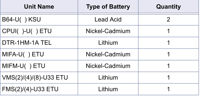
ISPOSALThe Xen IPK system includes the batteries listed below. When disposing of these batteries, KSUs and/or ETUs, you must comply with applicable Federal and State regulations regarding proper disposal procedures.
The Xen IPK CPUI( )-U( ) ETU provides memory backup for approximately 21 days. The Ni-Cd battery should be replaced about every two years.
IMPORTANT SAFEGUARDS FOR BATTERY DISPOSAL
DO NOT PLACE USED BATTERIES IN YOUR REGULAR TRASH! THE PRODUCT YOU PURCHASED CONTAINS A NICKEL-CADMIUM OR SEALED LEAD BATTERY. NICKEL-CADMIUM OR SEALED LEAD BATTERIES MUST BE COLLECTED, RECYCLED OR DISPOSED OF IN AN ENVIRONMENTALLY SOUND MANNER.
The incineration. landfilling or mixing of nickel-cadmium or sealed lead batteries with the municipal solid waste stream is PROHIBITED BY LAW in most areas. Contact your local solid waste management officials for other information regarding the environmentally sound collection, recycling and disposal of the battery.
Nickel-Cadmium (or sealed lead) batteries must be returned to a Federal or State approved nickel-cadmium (or sealed lead) battery recycler. This may be where the batteries were originally sold or a local seller of automotive batteries. Contact your local waste management officials for other information regarding the environmentally sound collection, recycling and disposal of the battery contained in this product.
Table 1-1: Battery Types and Quantities for KSUs and ETUs
Unit Name Type of Battery Quantity
B64-U( ) KSU Lead Acid 2
CPUI( )-U( ) ETU Nickel-Cadmium 1
DTR-1HM-1A TEL Lithium 1
MIFA-U( ) ETU Nickel-Cadmium 1
MIFM-U( ) ETU Nickel-Cadmium 1
VMS(2)/(4)/(8)-U33 ETU Lithium 1
4 - Chapter 1 Regulatory Information
Doc. No. 8
201 - Re
lease 1.0
July 2003
Doc.
No. 8201
Release 1.0
July 2003
Introduction
Chapter 2
S
ECTION
1
G
ENERALI
NFORMATIONDterm Series i (DTR telephones) and DTU-type multiline telephones can be used with the Xen IPK system.
S
ECTION
2
M
ULTILINET
ERMINALSU
SEDW
ITHT
HES
YSTEMDterm Series i Multiline Terminals
The Dterm Series i Multiline Terminals offer a variety of colours, display and non-display and line sizes.
Two colours are generally available: black and white.
Two display types: with LCD and without LCD. The large Liquid Crystal Display (LCD) on the display terminals provides call status data and programming information.
Four line sizes: 2-line, 8-line, 16-line and 32-line.
Speakerphones with full handsfree operation and headset jacks are standard (headset jack not available on the DTR-2DT-1A).
All but the DTR-2DT-1A are compatible with the AD(A)-R( ), AP(A)-R( ), AP(R)-AP(A)-R( ), CT(A)-AP(A)-R( ) Unit and CT(U)-AP(A)-R( ) Unit adapters. The AP(R)-R( ) Unit requires an ACA-U( ) Unit to supply AC power. The DTR-2DT-1A has an internal Analogue Port without ringer.
An Attendant Add-On DCR-60-1A CONSOLE is available with 60 station and/or outside line assignments and 12 function keys.
6 – Chapter 2 Introduction
Doc. No. 8
201 - Re
lease 1.0
July 2003
The Single Line Terminals are offered in two variations (DTR-1-1A and DTR-1HM-1A). Both have DTMF and Pulse Dialling compatibility, and offer Flash and Redial key functionality. These Single Line Terminals come standard with a Message Waiting Indicator that also functions as an Incoming Call Indication. During a call, the receive audio level can be increased three levels and decreased two levels from the default setting (six volume level settings in all). The terminals offer four ring volume settings (Off, Soft, Medium, and Loud), and three ring patterns (Slow, Medium, and Fast). The Single Line Terminals also have a Data Port for connecting a modem, and have a built-in wall mount adapter. The DTR-1HM-1A terminal has eight programmable speed dial buttons (maximum 21 digits each). The DTR-1HM-1A also has Hold and Monitor Function keys.
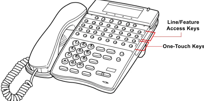
Dterm Series i Terminal Feature Access Single On/Off, or
One-Touch Keys
Keys are designated Feature Access, Single On/Off, or One-Touch throughout this manual. The keys operate much the same, but various limitations imposed on each type are described below.
Feature Access Keys
Depending on the type, a Multiline Terminal can have 2, 8, 16, or 24 line keys. These highly-flexible keys can be used for station DSS/BLF and Speed Dial.
Single On/Off Keys
Xen IPK Features and Specifications Manual
D
oc. N
o. 8201
Release
1.0
July 20
03
One-Touch Keys
One-Touch keys can perform the same function as Feature Access keys. A Multiline Terminal has a fixed number of these keys. No system assignment is necessary, and the number of keys ranges from none to 16 depending on the terminal type.
DTU-type Multiline Terminals
The DTU-type multiline telephones are available in a variety of colours, display and non-display types and line sizes.
Two colours are generally available: black and white.
Two display types: with LCD and without LCD. The large Liquid Crystal Display (LCD) on the display terminals provides call status data and programming information.
Three lines sizes: 8-line, 16-line and 32-line.
Speakerphones with full handsfree operation and headset jacks are standard.
The Dterm Series i Handset Cordless terminal is a 16-button phone (display only).
An Attendant Add-On DCU-60-1A(BK)/(WH) CONSOLE is available for 60 station and/or outside line assignments and 12 function keys.
An SLT Adapter can be used in place of a digital terminal for connecting Single Line Telephones, or similar devices.
Figure 2-1: Key Assignment Example
8 – Chapter 2 Introduction
Doc. No. 8
201 - Re
lease 1.0
July 2003
Doc.
No. 8201
Release 1.0
July 2003
Features
Chapter 3
S
ECTION
1
G
ENERALI
NFORMATIONAll features available with the Xen IPK system are listed alphabetically by name and described in this document. The following information is provided, when applicable, for each feature:
Feature Description — briefly describes the feature and, when applicable, tells how the feature is used by the end-user.
System Availability — describes Multiline Terminals that can be used with this feature and lists any additional equipment, such as adapters or ETUs, that must be installed for this feature to operate.
Operating Procedures – When applicable, detailed procedures for using the feature are provided.
Quick Access Code Reference – provides a table that lists any Access Codes that are used with the operation of the feature. This table is only included for those features that have associated Access Codes. This table has three columns: Default, Access Code Name, and Alphabetic Designation.
Default – indicates the default values for the Access Codes (i.e., the values as they are set when the system is first installed). All Access Codes can be changed in System Programming with the exception of the System and Fixed codes.
Access Code Name – indicates the name associated with the Access Code. At the end of each code name, in parenthesis, is the code type. There are four types of Access Codes: System, Feature, Intercom, and Fixed.
z System Codes are usually 1-digit codes that apply to the operation of the system. These codes can be changed in System Programming.
z Feature Codes are typically 3-digit codes and indicate Access Codes that apply to the associated feature, these codes can be changed in System Programming.
z Intercom Codes are 2-digit codes that apply to the associated feature and indicate Access Codes that can be changed in System Programming.
z Fixed Codes cannot be changed, they are set in the system.
10 – Chapter 3
Doc. No. 8
201 - Re
lease 1.0
July 2003
Service Conditions – provides specific conditions that apply to the operation of this feature.
Related Features Lists – lists any associated features.
S
ECTION
2
O
PERATINGP
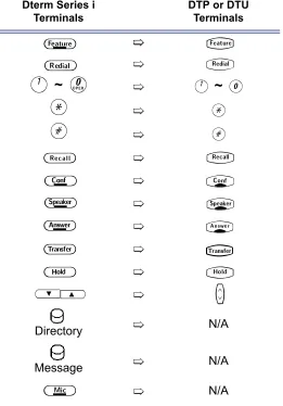
ROCEDURESThe operating procedures are the same for the Dterm Series i and DTU-Type and ETW-Type Multiline Terminals. The Dterm Series i terminals have three additional keys; MIC, Directory and Message. Minor differences in the keys are listed below. These differences are important when performing the operations listed in the remainder of this manual.
S
ECTION
3
F
EATURESFeatures that are available with the Xen IPK system are listed in the remainder of this chapter in alphabetical order by feature name.
Table 3-2: Comparison of Keys for Dterm Series i and DTU-type Multiline Terminals
Dterm Series i Terminals
DTP or DTU Terminals
A
~
K
A
~
0
J
J
L
L
Directory N/A
Message N/A
N/A
A
T
B
Q
C
S
D
R
E
P
F
O
G
N
H
U
UV
M
Doc.
No. 8201
Release 1.0
July 2003
Account Code Entry
A-1
FEATURE
DESCRIPTION
The Account Code Entry feature allows assignment of Account Codes up to 16 digits. Account Codes are incorporated in the call records generated by the Station Message Detail Recording (SMDR) option and provide a reference for billing.
SYSTEM
AVAILABILITY
Terminal Type
All terminals.
Required Components
MIFM-U( ) ETU
OPERATING
PROCEDURES
1. Press
T
.2. Dial Access Code
FF
(fixed Access Code).3. Enter the Account Code using the dial pad while talking with the outside party.
4. Press
T
.1. While receiving internal dial tone, dial Account Code Entry Access Code ________ (not assigned at default).
2. Enter the Account Code using the dial pad.
3. Retrieve the held call.
OR
-4. While receiving internal dial tone, press the Feature Access or One-Touch key programmed for Account Code Entry.
5. Enter the Account Code using the dial pad.
6. Retrieve the held call.
From a Multiline Terminal with an outside call in progress:
12 – A1 Account Code Entry
Doc. No. 8
201 - Re
lease 1.0
July 2003
1. Press the hookswitch, and receive a new internal dial tone; the outside party is put on hold.
2. Dial Account Code Entry Access Code ________ (not assigned at
default).
3. Enter the Account Code using the dial pad.
4. Provide a hookflash to return to the held call.
QUICK ACCESS
CODE
REFERENCE
SERVICE
CONDITIONS
Data Assignment
The Account Code Entry Access Code, used after a call has been put on hold (no default is provided), can be changed in System Programming.
The ability to enter an Account Code is determined by System Programming.
Restrictions
No Account Code can be entered when a station is a member of a conference supported by the system.
A hookflash results in a conference when a Single Line Telephone has a call on hold and another call is in progress. In this case, an Account Code cannot be entered.
An Account Code Entry does not print with SMDR unless the account code is entered after the Call Start Time elapses.
General
SMDR Reports on incoming calls is dependent on System Programming. When an Account Code is entered during an outgoing call, a call report is generated regardless of system assignment. Multiline Terminal users can enter an Account Code while talking with the outside party (no tones are sent to the CO line and the outside party is not put on hold).
If multiple Account Codes are entered during one call, the last entry is output from SMDR.
Account Code length can be up to 16 digits.
Account Codes can be programmed to a Feature Access or One-Touch key on any Multiline Terminal.
During Account Code Entry, Call Alert Notification is not provided. SMDR card must be present and enclosed in system programming for account codes to work.
From a Single Line Telephone with an outside call in progress:
Default Access Code Name DesignationAlphabetic
66 Account Code Entry (Feature Access - Fixed)
Xen IPK Features and Specifications Manual
D
oc. N
o. 8201
Release
1.0
July 20
03
RELATED
FEATURES LIST
GUIDE TO
FEATURE
PROGRAMMING
Feature
Number Feature Name
A-2 Account Code - Forced/Unverified
A-3 Account Code - Forced/Verified
S-15 Station Message Detail Recording (SMDR)
Order and Shortcut
System Data Name Memory Block Function
1-8-07 Attendant Page-Line
Key
1-8-08 Station Page-Line
Key
+BTS Class of Service (Station) Feature Selection 2 1-8-08 3-6
+BTT Station to Class of Service Feature Assignment 4-17
+BA Access Code (1-, 2-, or 3-Digit) Assignment 1-1-46/47/48 041
+BS Card Interface Slot Assignment 7-1
+BS MIF (SMDR) Assignment 7-3-02
+BS MIF (LCR) Assignment 7-3-01
+AS Printer Connected Selection 1-5-13
+AS Printer Line Feed Control Selection 1-5-14
+AS SMDR Incoming/Outgoing Print Selection 1-5-26
+AS SMDR Valid Call Time Assignment 1-5-25
+AS SMDR Print Format 1-5-02
+AS SMDR Telephone Print Selection 4-56
+CSS COM Port Baud Rate Setting Assignment 1-8-35
+BM Start Time Selection 1-1-0514 – A1 Account Code Entry
Doc. No. 8
201 - Re
lease 1.0
July 2003
Doc.
No. 8201
Release 1.0
July 2003
Account Code -
Forced/Unverified
A-2
FEATURE
DESCRIPTION
The Forced/Unverified Account Code feature forces the user to dial an access code and an Account Code before being able to select an outside line, but the account code entered is not verified against a list of stored numbers (as it is in the Forced/Verified Account Code feature). This in effect means that any number (of a specified length) can be entered without being restricted to a certain selection only. The Account Code entered is then presented in the SMDR report at the end of the call for account keeping or identification purposes.
SYSTEM
AVAILABILITY
Terminal Type
All Terminals
Required Components
MIFM-U( ) ETU
OPERATING
PROCEDURE
1. Lift the handset and wait for internal dial tone.
2. Dial the Forced Account Access Code. A second dial tone is received.
3. Dial the Forced/Unverified Account Code. Wait for internal dial tone.
4. Dial the Trunk Access code and the outside number.
1. Press the
V
(SYS. or STA softkey) to designate system or station speed dialling.2. Press the
V
(UP or DOWN softkey) to view the names/numbers listed in the directory.OR
-Press a dial pad key (to select the first letter of the name or number of the desired speed dial buffer) and dial
J
.3. To dial the number press
P
or lift the handset.4. Enter the Account Code.
To enter a Forced/Unverified Account Code from any station:
16 – A2 Account Code - Forced/Unverified
Doc. No. 8
201 - Re
lease 1.0
July 2003
SERVICE
CONDITIONS
Data Assignment
Use Memory Block 1-8-08 [Class of Service (Station) Feature Selection 2], Page 6 LK3 to Allow (LED On) or Deny (default: LED Off) Forced Account Code Unverified.
Use Memory Blocks 1-1-46~48 [Access Code (1-, 2-, or 3-Digit) Assignment] to assign the Forced Account Code Access (Function No. 147).
Use Memory Block 1-8-27 (Forced Account Code Length Assignment) to assign the number of digits for Account Codes system-wide. One to 13 digits can be assigned; default is 10 digits.
Use Memory Block 7-1 (Card Interface Slot Assignment) to specify the necessary MIFM-U( ) ETU.
Restrictions
Existing Code restrictions, Automatic Carrier Routing (ACR) and Least Cost Routing (LCR) assignments are applied after Forced Account Codes are entered.
Emergency 000 (111 NZ) calls cannot be made unless a valid Forced Account Code is entered.
A one-touch key must be programmed on these handsets allowing emergency number access.
Verified and Unverified Forced Account Codes cannot be used in the same Class of Service.
General
Only outgoing calls from Intercom require a Forced Account Code. Direct access to trunks bypasses this feature, that is, by pressing a line key, or dialling trunk access code.
The Forced Account Code without verification feature allows the user to place an outgoing call without Account Code verification only the length is verified.
Reorder tone is provided if an outgoing call is dialled without entering the Forced Account Code access code and a valid Forced Account Code.
Call Alert Notification is not provided during Account Code Entry.
PBR Timer values apply when using a Single Line Telephone to enter a Forced/Unverified Account Code.
Verified and Unverified Forced Account Codes will be printed on the SMDR report if both features are used.
An ’A’ is placed in front of the Forced/Unverified Account Codes on the SMDR reports to distinguish them from other Account Code entries.
Xen IPK Features and Specifications Manual
D
oc. N
o. 8201
Release
1.0
July 20
03
RELATED
FEATURES LIST
GUIDE TO
FEATURE
PROGRAMMING
Feature
Number Feature Name
A-1 Account Code Entry
A-3 Account Code - Forced/Verified
S-15 Station Message Detail Recording (SMDR)
Order and Shortcut
System Data Name Memory Block Function
1-8-07 Attendant Page-Line
Key
1-8-08 Station Page-Line
Key
+BA Access Code (1-, 2-, or 3-Digit) Assignment 1-1-46/47/48 146,147
+BTS Class of Service (Attendant) Feature Selection 1 1-8-07 2-8
+BTS Class of Service (Station) Feature Selection 2 1-8-08 5-1, 6-3
+AC Code Restriction Class Assignment (Day Mode) 4-07
+AC Code Restriction Class Assignment (Night Mode) 4-08
+BTT Station to Class of Service Feature Assignment 4-17
+AC Code Restriction Class (Without Authorisation Code) Day Mode Assignment 4-64
+AC Code Restriction Class (Without Authorisation Code) Night Mode Assignment 4-65
+BF Forced Account Code Length Assignment 1-8-27
+BS Card interface Slot Assignment 7-1
+BS MIF (SMDR) Assignment 7-3-02
+BS MIF (LCR) Assignment 7-3-01
+AS Printer Connected Selection 1-5-13
+ AS Printer Line Feed Control Selection 1-5-14
+ AS SMDR Incoming/Outgoing Print selection 1-5-2618 – A2 Account Code - Forced/Unverified
Doc. No. 8
201 - Re
lease 1.0
July 2003
+ AS SMDR Print Format 1-5-02
+AS SMDR Telephone Print Selection 4-56
+CSS COM Port Baud Rate Setting Assignment 1-8-35
+BM Start Time Selection 1-1-05When the system is at default this Memory Block must be programmed for the feature to be used. Order
and Shortcut
System Data Name Memory Block Function
1-8-07 Attendant Page-Line
Key
1-8-08 Station Page-Line
Doc.
No. 8201
Release 1.0
July 2003
Account Code -
Forced/Verified
A-3
FEATURE
DESCRIPTION
The Account Code - Forced/Verified feature forces selected station users to dial an Access Code and a verified Account Code before making an outgoing call. The outgoing call is processed only after the Dialled Account Code is verified. This feature allows a system administrator to control unauthorised outgoing calls. The Forced/Verified Account Code is part of the Station Message Detail Recording (SMDR) call record. The maximum number of digits for an Account Code is 13.
SYSTEM
AVAILABILITY
Terminal Type
All Terminals.
Required Components
MIFM-U( ) ETU
OPERATING
PROCEDURE
1. Lift the handset; receive internal dial tone.
2. Dial the Forced Account Access Code _______. (not assigned at default). A second dial tone is received.
3. Dial the Forced Account Code _______. Internal dial tone is received.
4. Dial the Trunk Access code and the outside number.
1. Lift the handset; receive internal dial tone.
2. Dial the Forced Account Access Code (not assigned at default). A second dial tone is received.
3. Dial the Forced Account Number (
00A
~E00
).4. Dial the Forced Account Code (default: 4 digits). Confirmation tone is received.
5. Press
N
to enter the information. The next Account Number is displayed. (Repeat steps 4 ~ 5 until all desired Account Codes are entered.)6. Press
P
to finish entering Account Codes.To enter a Forced/Verified Account Code from any station:
20 – A3 Account Code - Forced/Verified
Doc. No. 8
201 - Re
lease 1.0
July 2003
1. Press the
V
(SYS. or STA softkey) to designate system or station speed dialling.2. Press the
V
(UP or DOWN softkey) to view the names/numbers listed in the directory.OR
-Press a dial pad key (to select the first letter of the name or number of the desired speed dial buffer) and dial
J
.3. To dial the number press
P
or lift the handset.4. Enter the Account Code.
SERVICE
CONDITIONS
Data Assignment
Use Memory Block 1-8-07 [Class of Service (Attendant) Feature Selection 1] Page 2 LK8 to Allow (default LED On) or Deny (LED off) Attendant Positions to program Forced Account Codes.
Use Memory Block 1-8-08 [Class of Service (Station) Feature Selection 2] Page 5 LK1 to Allow (LED On) or Deny (default: LED Off) Account Code Forced/Verified.
Use Memory Block 1-8-27 (Forced Account Code Length Assignment) to assign the number of digits for Account Codes system-wide. One to 13 digits can be assigned; default is 4 digits.
Use Memory Block 7-1 (Card Interface Slot Assignment) to specify the necessary MIFM-U( ) ETU.
Xen IPK Features and Specifications Manual
D
oc. N
o. 8201
Release
1.0
July 20
03
Restrictions
Existing restrictions and Least Cost Routing (LCR) assignments are applied after Forced Account Codes are entered.
Emergency 000 (111 NZ) calls cannot be made unless a valid Forced Account Code is entered. In such cases, provide access to emergency numbers by programming them into One-Touch or Feature Access keys.
Verified and Unverified Forced Account Codes cannot be used in the same class of service.
General
Only outgoing calls from an intercom require a Forced Account Access Code. Direct access to trunks bypasses this feature.
Reorder tone is provided if an outgoing call is Dialled without entering the Forced Account Access Code and a valid Forced Account Code.
Call Alert Notification is not provided during Account Code Entry verification and programming.
PBR Timer values apply when using a Single Line Telephone to enter a Forced/Verified Account Code.
Forced Account Codes can be uploaded, downloaded, or modified using PC based System Programming.
Forced Account Code and Account Code entries print on the SMDR report if both are used.
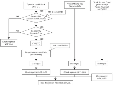
Figure A3-1: Account Code Forced/Verified
Speaker or Off Hook (ICM DT)
Correct F/V Account Code Access
Correct F/V Account Code
ICM (DT)
Enter trunk Access Code (Second DT)
MB 1-1-46/47/48
Dial Digits
Check against 4-07, 4-08 Error Displace
and Tone
MB 1-1-46/47/48
Press Off Line Key (Network DT)
Dial Digits
Check against 4-07, 4-08
Dial destination if number allowed.
NO NO YES YES YES Dial Digits Trunk Access Code
(Trunk Group Route Advance)
or CO/PBX
22 – A3 Account Code - Forced/Verified
Doc. No. 8
201 - Re
lease 1.0
July 2003
A
is placed in front of the Forced Account Codes on the SMDR reports to distinguish them from other Account Code entries.Attendant Positions can be used to program Forced Account Codes only if allow is assigned in Attendant Class of Service.
The maximum number of Forced Account Codes that can be entered system-wide is 500.
When the Interdigit time (default 10s) expires after the user inputs a Forced Account Code, busy tone is generated.
RELATED
FEATURES LIST
NumberFeature Feature NameA-1 Account Code Entry
A-2 Account Code - Forced/Unverified
Doc.
No. 8201
Release 1.0
July 2003
Add-On Conference
A-4
FEATURE
DESCRIPTION
The Add-On Conference feature allows a conference call with a maximum of four parties with various combinations of outside lines and stations. This increases efficiency by allowing multiple parties to enter into a conversation.
Up to sixteen 4-party conferences are allowed with no more than two outside lines per conference.
SYSTEM
AVAILABILITY
Terminal Type
All stations.
Required Components
None.
OPERATING
PROCEDURES
1. Press
R
.2. Dial a station number or outside party, and inform the answering party of the conference.
3. Press
R
again. TheR
LED lights solid. Talk with both parties.4. Repeat steps 1~3 to add an additional party to the conference.
1. Press the hookswitch to place the first call on hold.
2. Dial an internal station and announce conference.
3. Press the hookswitch again. Talk with both parties.
Note: Refer to Privacy Release, on Page 465 for a different method of entering conference.
To initiate an Add-On Conference using a Multiline Terminal with a call in progress:
24 – A4 Add-On Conference
Doc. No. 8
201 - Re
lease 1.0
July 2003
SERVICE
CONDITIONS
Restrictions
A Single Line Telephone cannot be used to originate a 2-party CO conference.
A Multiline Terminal user that is put on hold cannot enter into another conference.
General
The elapsed time of the call (from the originating terminal) is shown on all the Multiline Terminals with a display.
When all sixteen conference circuits are in use, the Conference key lights solid red on all Multiline Terminals.
Allowed conference configurations are:
z 4 terminals - no outside party z 3 terminals - 1 outside party z 3 terminals - no outside party z 2 terminals - 1 outside party z 1 terminal - 2 outside parties
Only one member of a conference can place a conference on hold at a time.
When the conference is placed on hold, theConference LED flashes on all phones in the conference.
No recall is provided at the Multiline Terminal when a conference is on hold.
The CO to CO db loss of conference is 6 db (3 db per CO).This value does not include the loss already occurring on each CO circuit. A telephone for conference connection incurs a 10 db loss in volume.
RELATED
FEATURES LIST
Features which can use conference circuits are: Voice Over Split (V-2), Live Recording (D-6), Barge-In (B-3), Unsupervised Conference (U-4) and Add-on CAdd-onference.
Feature
Number Feature Name
A-26 Automatic Release
Doc.
No. 8201
Release 1.0
July 2003
All Call Page
A-5
FEATURE
DESCRIPTION
The All Call Page feature allows simultaneous paging (internal and external) of all idle Multiline Terminals in a zone over their built-in speakers and over all external paging speakers. This enables a person, away from their desk but within hearing distance of a Multiline Terminal or external speaker, to respond to the paging call.
SYSTEM
AVAILABILITY
Terminal Type
All Terminals.
Required Components
None.
OPERATING
PROCEDURES
1. Lift the handset, and receive internal dial tone (or press
U
, if the user is already engaged on a call).2. Dial Access Code
EI
(set as default) for All Call Page.3. Page.
1. Go off-hook.
2. Receive internal dial tone.
3. Dial Meet-Me Access Code
EJ
(set as default); the display changes to show the originator station number.4. Talk with All Call Page originator.
To originate a page on a Multiline Terminal:
26 – A5 All Call Page
Doc. No. 8
201 - Re
lease 1.0
July 2003
1. Lift the handset, and receive internal dial tone or press the hookswitch if the user is already engaged in a call.
2. Dial Access Code
E
I
(set as default) for All Call Page.3. Page.
1. Lift the handset or press the hookswitch if the user is already engaged in a call.
2. Receive dial tone.
3. Dial Meet-Me Access Code
E
J
(set as default).4. Talk with All Call Page originator.
QUICK ACCESS
CODE
REFERENCE
SERVICE
CONDITIONS
Data Assignment
Stations can be allowed or denied receiving paging through System Programming. This includes All Call Page, Internal Zone Paging, and External Zone Paging. This does not include Internal Emergency All Call Page.
In System Programming, paging alert tone (Internal and/or External) can be allowed or denied system-wide. The default assignment is Receive Paging Alert Tone.
Restrictions
Multiline Terminal users engaged in a handsfree call do not receive All Call Page or Internal Zone Pages.
Multiline Terminals provided with Off-Hook Voice Announcement cannot receive All Call Page when already engaged in a call.
Only one All Call Page or Internal Zone Page can be established at a time. Another page can be originated as soon as the first is abandoned or answered (by Meet-Me Answer).
To originate a page on a Single Line Telephone:
To answer a page on a Single Line Telephone:
Default Access Code Name DesignationAlphabetic
59 All Internal/External Zone Paging N/A
Xen IPK Features and Specifications Manual
D
oc. N
o. 8201
Release
1.0
July 20
03
Simultaneous zone paging (Internal Zones A, B, and C) can be established at one time; however, All Internal Zone Paging and Internal Emergency All Call Page cannot be performed if any other internal page is in use.
General
All Call Page can be originated or answered (by Meet-Me Answer) from internal dial tone.
All Call Page times out using the External Paging Time Out with a default time of five minutes.
An outside line can be conferenced with External Page to allow a conversation to be monitored.
The default Access Code for All Call Page is 59. The default Access Code for All Call Page Meet-Me code is 5
*
(Internal/External Meet Me).RELATED
FEATURES LIST
GUIDE TO
FEATURE
PROGRAMMING
FeatureNumber Feature Name
E-1 Elapsed Call Timer
I-6 Internal Zone Paging (Meet Me)
Order and Shortcut
System Data Name Memory Block Function
1-8-07 Attendant Page-Line Key 1-8-08 Station Page-Line Key
+BA Access Code (1-, 2-, or 3-Digit) Assignment 1-1-46/47/48 070~079, 081
+BTM Internal Zone Paging Selection 4-93
+BTT Receiving Internal/All Call Page Selection 4-31
+BP Internal Paging Alert Tone Selection 1-2-25
+BP Internal Paging Timeout Selection 1-2-00
+BP External Speaker Connection Selection 1-7-02
+BP External Paging Alert Tone Selection 1-7-0328 – A5 All Call Page
Doc. No. 8
201 - Re
lease 1.0
July 2003
+BP External Speaker Chime Start time Selection 1-7-09
+BP External Paging Timeout Selection 1-7-06Order and Shortcut
System Data Name Memory Block Function
1-8-07 Attendant Page-Line
Key
1-8-08 Station Page-Line
Doc.
No. 8201
Release 1.0
July 2003
Alphanumeric Display
A-6
FEATURE
DESCRIPTION
Each Display Multiline Terminal is equipped with a 24-character by 3-line Liquid Crystal Display (LCD). These displays provide information such as: date/time, elapsed call time on outside calls, digits Dialled, internal calling party number, Customised Message, and Speed Dial entries.
SYSTEM
AVAILABILITY
Terminal Type
All Multiline Terminals with a Display.
Required Components
None.
LCD DISPLAYS
Display Location Definition
12:24 AM WED 10 All Stations
with LCD
Clock/Calendar
FWD 100 - > [ ] Set Call Forward - All Calls
ALL FWD CANCLD Cancel DND/Call Forward - All Calls System-Wide
FWD/DND CANCLD Originator Cancel DND/Call Forward - All Calls At Individual Stations FWD SET [ ] Originator Set Call Forward - All Calls From Forward To Extension
FWD RESET [ ] Reset Call Forward - All Calls From Forward To Extension
BUSY 100 -- > [ _ ] Set Call Forward - Busy
FWD BUSY CANCLD Cancel Call Forward - Busy
NOANS 100 - > [ ] Set Call Forward - No Answer
FWD NA CANCLD Cancel Call Forward - No Answer
FWD BNA - > [ ] Set Call Forward Busy - No Answer
FWD BNA CNCL Cancel Call Forward Busy - No Answer
BACK MM/DD HH:MM Set Customised Message
MESSAGE CLEAR Cancel Customised Message System-Wide or From Individual
Station
NIGHT MODE SET Night Mode Switch
NIGHT MODE RESET Reset Night Mode
NT TENANT Set Night Mode For Tenant
30 – A6 Alphanumeric Display
Doc. No. 8
201 - Re
lease 1.0
July 2003
FNC LAMP OFF Reset FNC LED
CURRENT PASSWORD ? Originator Telephone Password (1)
NEW PASSWORD ? Originator Telephone Password (2)
ENTER PASSWORD Originator Set Password (CO/PBX Restriction)
RESTRICT SET Originator After Setting Password
CALL DENIED Originator Display on Station Outgoing Restricted Telephone
RESTRICT CANCLD Originator After Cancelling Outgoing Call Restriction
CANCEL TEL Cancel Restriction on Another Telephone
RLY 0 ON Relay On
RLY 0 OFF Relay Off
ALARM AM 00 : 00 Set Alarm For A.M.
ALARM PM 00 : 00 Set Alarm For P.M.
ALL ALARM CANCLD Cancel Alarm System-Wide
SET TIME REMINDR Set Timed Alarm for SLT
DND SET Originator Set Do Not Disturb
*<– – XXXXXXXXXX Originator Save and Repeat Number Is Stored
ALL PAGE Originator Internal All Zone Paging
GROUP [ A ] Group Paging
SPKR [ A ] Originator External Speaker
TRF SET CO = Set Automatic Tandem Trunk Transfer IN/OUT Trunk
TRF CNCL CO = Reset Automatic Tandem Trunk Transfer
TRF TO CO = Set or Confirm Transferred Trunk of Automatic Tandem Trunk
Transfer
TRNS TO N / A Transferred Trunk Not Assigned
00 : EMPTY No Speed Dial Number Entered
00 : 0 1 2 3 4 5 6 7 8 9 Speed Dial Number Confirmation
NO SMDR Station Message Detail Recording Not Available
ERROR Error Message
BUSY Busy Message
PRINTER TROUBLE Printer Problems
SPKR [ A , B , C ] Originator External All Paging
LINE IDLE Originator Trunk Queuing; CO/PBX Trunk Idle
TRUNK QUE SET Originator Trunk Queuing Set
LNR [ # ] / SPD [ ] Press LNR/SPD Key
TRUNK QUE CANCLD Originator Trunk Queue cancelled
Xen IPK Features and Specifications Manual
D
oc. N
o. 8201
Release
1.0
July 20
03
SERVICE
CONDITIONS
French, Spanish and Japanese characters are also available for some displayed test.
RCL : 0 1 , 0 2 , 0 3 , 0 4 Originator Hold Recall 120 < - [ 1 1 0 ] TRANSF Destination Ring Transfer
120 = = [ 1 1 0 ] TRANSF Automatic Ring Transfer
OVD > [ ] Barge-In On CO/PBX Line (1)
OVD - > CO [ ] Barge-In On CO/PBX Line (2)
100 < - TIE LN — Tie Line Answer
100 < - DID LN — DID Answer
DATA ENTRY Enter Data Via System Programming
STA NUMBER? Call Pickup Direct Originate
100 _ _ [101]URGENT Voice Over Split Originate/Receive
01/12147517627 Caller ID Indication
MUSIC SET/RESET Background Music is On/Off
100 Extension number only to be displayed at idle
NAME Extension name only to be displayed at idle
10 NAME Extension No.2 digits with number and name display
100 NAME Extension No.3 digits with number and name display
1000 NAME Extension No.4 digits with number and name display
32 – A6 Alphanumeric Display
Doc. No. 8
201 - Re
lease 1.0
July 2003
GUIDE TO
FEATURE
PROGRAMMING
Order and Shortcut
System Data Name Memory Block Function
1-8-07 Attendant Page-Line
Key
1-8-08 Station Page-Line
Key
+BCT Trunk Name/Number Assignment 3-00
+BTT Station Name Assignment 4-18
+BE Speed Dial Number/Name Display Selection 1-1-33
+BI Customised Message 1~10 Assignment 1-2-09~18
+BTM Multilingual LCD Indication Selection 4-28Doc.
No. 8201
Release 1.0
July 2003
Ancillary
Device Connection
A-7
FEATURE
DESCRIPTION
The Ancillary Device Connection feature allows installation of selected peripheral (ancillary) devices such as an amplified handset, headset, Analogue telephone devices, or external speakerphone for use on any Multiline Terminal. This feature enhances operation for which the peripheral devices are designed.
A Dterm Series i Terminal user can accomplish this by using the AP(R)-R( ) Unit (Analogue Port Adapter with Ringer) or AP(A)-R( ) Unit (Analogue Port Adapter without Ringer) for analogue telephone devices, or installing the AD(A)-R( ) Unit to connect devices such as tape recorders.
The AP(A)-R( )/AP(R)-R( ) Unit is the interface for installing a Single LIne Telephone, Modem, Credit Card Reader, Wireless Headset, Conferences unit or other compatible analogue devices.
SYSTEM
AVAILABILITY
Terminal Type
Dterm Series i Multiline Terminals, except DTR-2DT-1A.
Required Components
AD(A)-R( ), AP(A)-R( ), AP(R)-R( )
OPERATING
PROCEDURES
SERVICE
CONDITIONS
Data Assignment
Use Memory Block 1-1-02 (Hookflash Time Selection) to specify the loop open time for a hookflash signal sent to the CO/PBX when the recall key on a Multiline Terminal is pressed.
Use Memory Block 1-3-02 (SLT Hookflash Signal Selection) to specify whether a line is held internally or, if behind a PBX, a hookflash (HF) signal is sent to the line when a Single Line Telephone user performs a hookflash.
Use Memory Block 4-24 (SLT Hookflash Assignment) to either hold or disconnect the trunk for the Single Line Telephone (SLT) hooking operation.
Use Memory Block 4-39 (APR Ring Mode Assignment) to assign the AP(R)-R( ) Unit for NON (No Ring), STA (default: ring Station Number only) or ALL.
Use Memory Block 4-59 (APR Hookflash Selection) to allow or deny hookflash on an AP(R)-R( ) unit.
34 – A7 Ancillary Device Connection
Doc. No. 8
201 - Re
lease 1.0
July 2003
General
The optional devices fit underneath the appropriate terminal.
An AP(A)-R( ) or AP(R)-R( ) Unit with hookflash enabled follows the same operating procedures as a Single Line Terminal connected to an SLI( )-U( ) ETU.
GUIDE TO
FEATURE
PROGRAMMING
Order and Shortcut
System Data Name Memory Block Function
1-8-07 Attendant Page-Line
Key
1-8-08 Station Page-Line
Key
+BTM APR Ring Mode Assignment 4-39
+AU APR/APA Hookflash Selection 4-59
+BTI DTMF/DP SLT Type Selection 4-95
+BTI SLT Hookflash Signal Selection 1-3-02
+BCM Hookflash Time Selection 1-1-02Doc.
No. 8201
Release 1.0
July 2003
Answer Hold
A-8
FEATURE
DESCRIPTION
The Answer Hold feature enables a Multiline Terminal user to press the flashing Answer key to answer an incoming ringing call on a CO line key. If the Multiline Terminal user is already engaged in a call, the first call is automatically placed on Non-Exclusive Hold when the second call is answered. Answer Hold is particularly useful at Attendant Positions or other central answering positions. Using the Answer key speeds call handling, while Answer Hold prevents accidental call dropping.
SYSTEM
AVAILABILITY
Terminal Type
All Multiline Terminals.
Required Components
None.
OPERATING
PROCEDURES
1. Receive CO/PBX incoming ring. The
O
LED flashes.2. Press
O
, and answer the new call (O
LED goes off). The original call is put on Hold.a. If the original call was on a Call Appearance Key, the call is placed on Non-Exclusive Hold on the Call Appearance Key.
b. If the call was on a line key, the call is placed on Non-Exclusive Hold on the line key.
3. Talk with the CO/PBX incoming caller.
4. If additional calls are received, press
O
to place the current call on Hold and connect to the next call. (Refer to a. and b. above.)SERVICE
CONDITIONS
Restrictions
The Answer Hold feature does not function for incoming internal calls. CO/PBX incoming calls not assigned to ring or assigned to other tenants do not activate the Answer Hold feature.
DID/Tie line and DIT/ANA calls do not activate the Answer Hold feature.
If all the Call Appearance keys are in use, the next call cannot be answered.
36 – A8 Answer Hold
Doc. No. 8
201 - Re
lease 1.0
July 2003
General
CO/PBX ringing transfer/camp-on calls may be answered.
If multiple incoming calls activate the Answer key LED, the LED continues to flash until all the calls are answered.
GUIDE TO
FEATURE
PROGRAMMING
Order and Shortcut
System Data Name Memory Block Function
1-8-07 Attendant Page-Line
Key
1-8-08 Station
Page-Line Key
+BTT CO/PBX Ring Assignment (Day Mode) 4-01
+BTT CO/PBX Ring Assignment (Night Mode) 4-02
+BTM Line Key Selection for Telephone Mode 4-12
+BTM Extension Line Key Ring Assignment (Day Mode) 4-37
+BTM Extension Line Key Ring Assignment (Night Mode) 4-38
+BTP Doorphone Chime Assignment (Day Mode) 4-03
+BTP Doorphone Chime Assignment (Night Mode) 4-04
+BTS Off-Hook Ringing Selection 4-51
+BM Hold Recall Time Selection (Non-Exclusive Hold) 1-1-03Doc.
No. 8201
Release 1.0
July 2003
Answer Key
A-9
FEATURE
DESCRIPTION
Multiline Terminals are equipped with an Answerkey and associated LED. The Answer key LED flashes when the Multiline Terminal user receives an incoming CO/PBX, Tie/DID transferred, and CO/PBX transferred call ringing/or not ringing in the same tenant group. When multiple calls are received, the Answer key is used to pick up calls. The Answer key continues flashing until the last unanswered call is answered. Press the Answer key during a call to hold the current call and allow the next call to be answered.
SYSTEM
AVAILABILITY
Terminal Type
All Multiline Terminals.
Required Components
None.
OPERATING
PROCEDURES
1. Receive CO/PBX incoming ring or flashing MW lamp without ringing.
O
LED flashes.2. Press
O
. TheO
LED goes out.3. Talk with the CO/PBX incoming calling party.
4. If additional CO incoming calls are received, the
O
LED flashes again. PressO
to place the current call on Non-Exclusive Hold and connect the Multiline Terminal user to the next call.a. If the original call was on a Call Appearance Key, the call is placed on Non-Exclusive Hold on the Call Appearance Key.
b. If the call was on a line key, the call is placed on Non-Exclusive Hold on the line key.
SERVICE
CONDITIONS
Restrictions
Internal calls, internal transfer/camp-on calls, Secondary Incoming Extension, Automated Attendant, and Tie/DID calls do not activate the Answer key LED.
38 – A9 Answer Key
Doc. No. 8
201 - Re
lease 1.0
July 2003
General
The Answer key LED functions for incoming CO/PBX calls, CO/PBX transfer/camp-on calls, and transferred/camped-on Tie/DID calls.
Incoming CO/PBX ringing calls to other tenants, with the CO/PBX line appearance and with or without ring assignment, activate the Answer key LED.
Incoming calls answered by the Answer key are handled on a first in-first out basis.
GUIDE TO
FEATURE
PROGRAMMING
Order and Shortcut
System Data Name Memory Block Function
1-8-07 Attendant Page-Line
Key
1-8-08 Station Page-Line
Key
+BTT CO/PBX Ring Assignment (Day Mode) 4-01
+BTT CO/PBX Ring Assignment (Night Mode) 4-02
+BTM Line Key Selection for Telephone Mode 4-12
+BTM Extension Line Key Ring Assignment (Day Mode) 4-37
+BTM Extension Line Key Ring Assignment (Night Mode) 4-38
+BTP Doorphone Chime Assignment (Day Mode) 4-03
+BTP Doorphone Chime Assignment (Night Mode) 4-04
+BCT DIT Assignment 3-42
+BCT ANA Assignment 3-43
+BTS Off-Hook Ringing Selection 4-51
+BTT CO/PBX Answer Key Operation Without Ringing Assignment (Day Mode) 4-52
+BTT CO/PBX Answer Key Operation Without Ringing Assignment (Night Mode) 4-53Doc.
No. 8201
Release 1.0
July 2003
Assigned Night Answer
(ANA)
A-10
FEATURE
DESCRIPTION
The Assigned Night Answer (ANA) feature is a Direct Inward Termination programmed to ring directly at a selected station when the system or tenant is in the Night Mode. This assignment operates independently from the DIT (Day Mode) ringing assignment.
SYSTEM
AVAILABILITY
Terminal Type
All terminals.
Required Components
None.
OPERATING
PROCEDURES
SERVICE
CONDITIONS
Data Assignment
CO/PBX lines can be assigned to ring a station number, a hunt group master number, or an ACD/UCD Pilot number.
Multiple CO/PBX lines can be assigned to ring at the same station, hunt group master number, or ACD/UCD Pilot number.
Incoming ANA calls follow the station Call Forward setting.
Restrictions
When a CO/PBX line is assigned for ANA, the Night Mode CO/PBX ring assignment is disabled.
General
ANA incoming ringing is assigned for Distinctive Ring or Synchronous Ring system-wide.
When a busy station, programmed for ANA, receives an incoming ANA call, the system provides Camp-On tone for the busy station. The calling party receives ringback tone until the call is answered.
A Call Pickup for the same tenant, Access Code 68 (set at default), can be used to answer ANA calls.
ANA calls do not activate External Tone Ringer or Night Chime.
40 – A10 Assigned Night Answer (ANA)
Doc. No. 8
201 - Re
lease 1.0
July 2003
ANA calls can be assigned to ring on voice mail ports. A hunt group can be assigned by using the internal master hunt number assignments.
When a station, programmed for ANA, receives an incoming ANA call, internal ring tone is heard at all stations where a secondary incoming extension appeACR and is assigned to ring.
Incoming ANA calls cannot be answered directly at the CO line key appearance. The CO line key indicates Other Use (red LED).
While receiving an incoming ANA call, an internal call cannot be made.
ANA or DIT ringing can be delayed for 0, 5, 10, 20, 30, 40, 50, 60 seconds.
RELATED
FEATURES LIST
GUIDE TO
FEATURE
PROGRAMMING
Feature
Number Feature Name
D-10 Direct Inward Termination (DIT)
Order and Shortcut
System Data Name Memory Block Function
1-8-07 Attendant Page-Line
Key
1-8-08 Station Page-Line
Key