Design and Implementation of a Smart Fire
Extinguisher using FPGA
Himadri Bhusan Satyanarayan Das1, K.C. Bhuyan2, Anwesha Panigrahi3
PG Student [EIE], Dept. of I&E, College of Engineering & Technology, Bhubaneswar, Odisha, India1
Assistant Professor, Dept. of I&E, College of Engineering & Technology, Bhubaneswar, Odisha, India2
PG Student [EIE], Dept. of I&E, College of Engineering & Technology, Bhubaneswar, Odisha, India3
ABSTRACT: This paper presents the design and Implementation of a smart fire extinguisher using FPGA. In this design, two temperature sensors mounted on a servo motor are used to locate the position of the fire. The movement of the servo motor is done through pulse width modulation (PWM) which has been written using verilog code. The implementation is done in a Spartan-6 FPGA board. The test result shows that the time required to detect the fire is approximately 20ms. The fire extinguisher is getting activated within 50ms (approximately) of the detection of the fire. The complete design utilizes 32 Slice Registers and 73 Slice LUTs.
KEYWORDS: FPGA, LUT, Spartan-6, Verilog, PWM
I.INTRODUCTION
Home fire detection is a matter of great concern and thus needs an automatic detection system. Many efforts are devoted in most developed countries to the design of automatic fire detection systems [1], [2]. It is very critical for the personal security and commercial applications.
An automatic fire detection system should reliably and timely alert the residents about the presence of fire indicators, such as smoke or high temperatures. In general a fire detector is usually implemented as a smoke sensor [3] due to its early fire detection capability, fast response time and relatively low cost. Other options for the fire detection are based on gas sensors [4], [5], [6] or temperature sensors. Fire detectors that use a single sensor, generally a smoke sensor, present high false-alarm rates due to temperature changes [2], [7].
In literature [1] and [2], J. Vicente et.al and V. Cappellini et al. demonstrated the importance and need of designing a smart fire extinguisher. Smart fire extinguishers can be applicable to all areas of fire prevention and protection. It addresses all phases of resilience (i.e pre-incident, during incident and post-incident). Van Nguyen et al.[3], Patricio et al.[4] and Chance et al.[5] have introduced various instructions and guidelines to use the smart fire extinguisher. Fire prevention is generally achieved by enhancing the power of information through enhanced data gathering, processing and targeted communication. Various implementation techniques for different fire extinguishers are described in [6] and [7].
In this paper, the design of a smart fire extinguisher is presented which has been implemented in Spartan-6 FPGA board and successfully tested. The detection of fire takes approximately 20ms and the fire extinguisher gets activated within 50ms of the detection of the fire. The organization of this paper is as follows: Section 2 introduces the Architecture and implementation of the smart fire extinguisher. Section 3 elaborates the results and discussion of the smart fire extinguisher. Finally, Section 4 concludes the paper.
II.ARCHITECTURE AND IMPLEMENTATION OF THE SMART FIRE EXTINGUISHER
The outputs of both the ADCs are used as the input to the Spartan-6 FPGA. The servo motor control is done through pulse width modulation which has been written using Verilog code. The ADC outputs are used as inputs to the Verilog code. Depending upon the values of these inputs, the position of the servo motor is decided. The initial position of the servo is set at the centre position. Now, if ADC-1 output is greater than ADC-2 output, the servo motor moves to left side from its initial position and if ADC-1 output is less than ADC-2 output the servo motor moves to right side from its initial position. This means the pulse width is either decreasing or increasing depending upon the values of the ADC outputs. Once, both the ADC outputs are getting equal, the servo motor stops rotating. This happens when the fire is exactly at the centre of both the temperature sensors. Now, one of the ADC output is given to the DAC input. Once both the outputs of ADC are equal, the DAC is activated and it then set off the water pump. With the decrease in temperature, the ADC outputs are getting decreased, which decreases the DAC input and hence the voltage to the water pump. This decrease in voltage level of the water pump slowly reduces the water flow and hence efficiently utilizes the water to douse the fire flames.
The design has been implemented using Spartan-6 FPGA board. The summery shows that the design utilizes 32 Slice Registers and 73 Slice LUTs. The design summery result has been shown in Fig 4.
Fig. 4: Design summary of the smart fire extinguisher
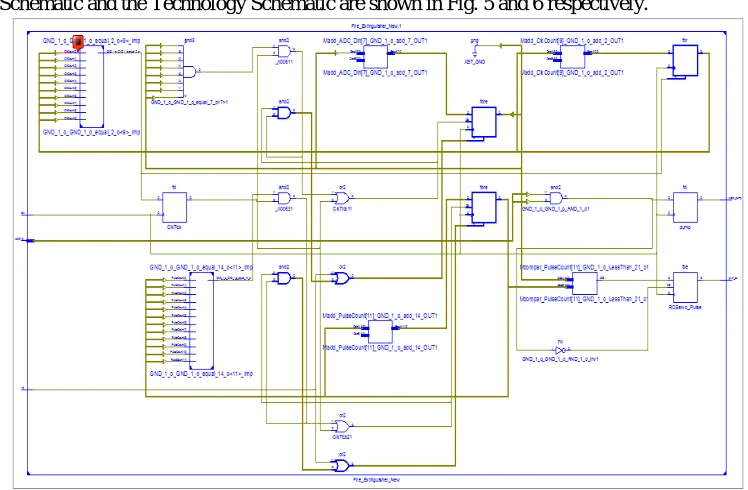
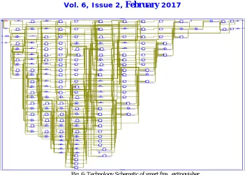
The RTL Schematic and the Technology Schematic are shown in Fig. 5 and 6 respectively.
Fig. 6: Technology Schematic of smart fire extinguisher
Fig. 7 shows the FPGA board which has been used to implement the smart fire extinguisher. In this board Spartan-6 FPGA is used. A crystal oscillator generating a clock of 100MHz is used as the clock pulse for this Spartan-6 FPGA. This module uses +5V power supply to function properly. By default the board is configured to use +5V supply from USB. So an external +5V power is not required unless USB port is unable to supply enough current. This board is equipped with 32 user IO pins that can be used for various custom applications. For our design, we have used these IO pins for connecting the ADC outputs and DAC input. Also to drive the servo motor theseports are used.
Fig. 7: Spartan-6 FPGA board
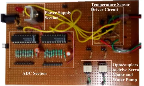
Fig. 8: Circuit board used to interface FPGA, servo motor and the water pump
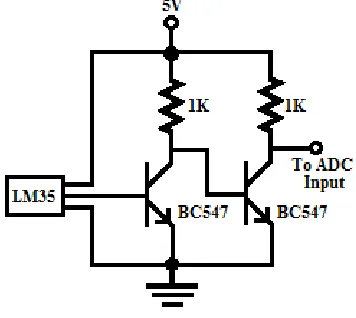
The water pump needs a power supply of 12V which is given from another power supply. For sensing the temperature generated from fire, we have used LM35 temperature sensor. The driver circuit is designed using two BC547 transistors. The resistivity of the temperature sensor changes with the change in temperature which determines the output of the driver circuit. When the temperature is low, the output is low and with the increase in temperature, the output also increases.
III. RESULT AND DISCUSSION
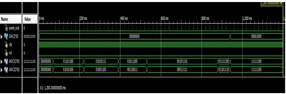
The simulation result of the smart fire extinguisher is shown in Fig. 9 (a) and (b) respectively. As shown in Fig. 9(a), the PWM pulse is increasing gradually because the value of ADC-1 is greater than ADC-2. The PWM is necessary to control the position of the servo motor.
Fig. 9(a) Test bench simulation results of the smart fire extinguisher with 1200ms time period
pour water on the fire. The value of DAC will gradually decrease with the decrease in temperature. This helps in saving water and hence results in better water and power management.
Fig. 9(b): Test bench simulation results of the smart fire extinguisher with 1200ms time period
IV.CONCLUSION
In this paper, a smart fire extinguisher is designed using Field Programmable Gate Array which utilizes 32 slice registers and 73 slice LUTs. The design has been implemented in a Spartan-6 FPGA board. The test result shows that the time required to detect the fire is approximately 20ms. The fire extinguisher is getting activated within 50ms approximately of the detection of fire. Therefore, this fire extinguisher can be used effectively in buildings where chances of fire occurrence are more.
REFERENCES
[1] Vicente J., Guillemant P., “An image processing technique for automatically detecting forest fire”, International Journal of Thermal Science,
41(12), pp.1113-1120, December 2002.
[2] Cappellini V., Mattii L. and Mecocci A., “ An intelligent system for automatic fire detection in forests”, Third International Conference on
Image Processing and its Applications, 1989.
[3] Nguyen,Van,T., Kim Jin Gook, Choi Deokjai, “ ISS: The Interactive Smart home Simulator”, International Conference on Advanced
Communication Technology, vol.03, pp.1828-1833, Feb. 2009.
[4] Patricio, G., Gomes, L., “ Smart house monitoring and actuating system development using automatic code generation,” 7th IEEE International
Conference on Industrial Informatics, June 2009.
[5] Elliott Chance, Vijayakumar Vipin, Zink Wesley and Hansen Richard, “National Instruments LabVIEW: A programming environment for
laboratory automation and measurement”, National Instruments, 2007.
[6] Feo Aernis, S., Westphal, B., Dietsch, D., Muniz, M., Siyar Andisha, “The Wireless fire alarm system: Ensuring conformance to industrial standards through formal verification”. In lecture Notes in Computer Science; Springer International Publishing: Cham, Switzerland, 2014.
[7] Chen, S.-J., Hovde, D.C., Peterson, K.A., Marshall, A.W., “Fire detection using smoke and gas sensors”. Fire Safety Journal. Vol.42,
pp.507-515, 2007.
[8] Aleksic, Z.J. “The analysis of the transmission-type optical smoke detector threshold sensitivity to the high rate temperature variations”, IEEE
Tran. Instrum. Meas., Vol. 53, pp.80-85, 2004.
[9] Kumbhare Manish, Kumbhalkar S.S., Ratneshmalik, “ Fire fighting robot; an approach”, Indian Streams Research Journal, Vol.2,2012.