ND-45670 (E) ISSUE 2 PART OF STOCK # 151901
Feature Programming Manual
functions, or features, at any time, without notice.
NEC America, Inc. has prepared this document for use by its em-ployees and customers. The information contained herein is the property of NEC America, Inc. and shall not be reproduced without prior written approval from NEC America, Inc.
NEAX and Dterm are registered trademarks of NEC Corporation. Copyright 1997
ADDENDUM-001 ADDENDUM-002 ADDENDUM-003 ADDENDUM-004
DATE JULY, 1998 DATE JANUARY, 1999 DATE DATE
ADDENDUM-005 ADDENDUM-006 ADDENDUM-007 ADDENDUM-008
DATE DATE DATE DATE
PAGE No.
ADD. No.
001 002 003 004 005 006 007 008 i
ii 2.1
iii 2.1
iv 2.1 2.2
v 2.1 2.2
vi vii viii 1 2 3 4 5 6 7 8 9 10 11 12 13 14 15 16 17 18 19 20 21 22 23 24 25 26 27 28 29 30 31 32 33 34 35 36 37 38 39 40 41 42 43 44 45 46 47 48 49 50 51 52 53 54 55 56 57 58 59 60 61 62 63 64 65 66 67 68 PAGE No. ADD. No.
ADDENDUM-001 ADDENDUM-002 ADDENDUM-003 ADDENDUM-004
DATE JULY, 1998 DATE JANUARY, 1999 DATE DATE
ADDENDUM-005 ADDENDUM-006 ADDENDUM-007 ADDENDUM-008
DATE DATE DATE DATE
NEAX2000 IVS
Feature Programming Manual Addendum Revision Sheet 2/7
ND-45670 (E) ISSUE 2
69 70 71 72 2.2 73 74 2.2 75 76 77 78 79 80 81 82 83 84 85 86 2.2 87 2.2
88 2.1 2.2
ADDENDUM-001 ADDENDUM-002 ADDENDUM-003 ADDENDUM-004
DATE JULY, 1998 DATE JANUARY, 1999 DATE DATE
ADDENDUM-005 ADDENDUM-006 ADDENDUM-007 ADDENDUM-008
DATE DATE DATE DATE
145 146 147 148 149 150 151 152 153 154 155 156 157 158 159 160 161 162 163 164 165 166 167 168 169 170 171 172 173 174 175 176 177 178 179 180 181 182 PAGE No. ADD. No.
001 002 003 004 005 006 007 008
183 184 185 186 187 188 189 190 191 192 193 194 195 196 197 198 199 200 201 202 203 204 205 206 207 208 209 210 211 212 213 214 215 216 217 218 219 220 PAGE No. ADD. No.
ADDENDUM-001 ADDENDUM-002 ADDENDUM-003 ADDENDUM-004
DATE JULY, 1998 DATE JANUARY, 1999 DATE DATE
ADDENDUM-005 ADDENDUM-006 ADDENDUM-007 ADDENDUM-008
DATE DATE DATE DATE
NEAX2000 IVS
Feature Programming Manual Addendum Revision Sheet 4/7
ND-45670 (E) ISSUE 2
ADDENDUM-001 ADDENDUM-002 ADDENDUM-003 ADDENDUM-004
DATE JULY, 1998 DATE JANUARY, 1999 DATE DATE
ADDENDUM-005 ADDENDUM-006 ADDENDUM-007 ADDENDUM-008
DATE DATE DATE DATE
293 294 295 296 297 298 299 300 301 302 303 304 305 306 307 308 309 310 311 312 313 314 315 316 317 318 319 320 321 322 323 324 325 326 327 328 329 330 PAGE No. ADD. No.
001 002 003 004 005 006 007 008
331 332 333 334 335 336 337 338 339 340 341 342 343 344 2.1 345 346 347 348 348-1 2.1 348-2 2.1 349 349-1 2.1 349-2 2.1 350 351 352 353 354 355 356 357 358 2.2 359 2.2 359-1 2.2 359-2 2.2 359-3 2.2 359-4 2.2 360 PAGE No. ADD. No.
ADDENDUM-001 ADDENDUM-002 ADDENDUM-003 ADDENDUM-004
DATE JULY, 1998 DATE JANUARY, 1999 DATE DATE
ADDENDUM-005 ADDENDUM-006 ADDENDUM-007 ADDENDUM-008
DATE DATE DATE DATE
NEAX2000 IVS
Feature Programming Manual Addendum Revision Sheet 6/7
ND-45670 (E) ISSUE 2
ADDENDUM-001 ADDENDUM-002 ADDENDUM-003 ADDENDUM-004
DATE JULY, 1998 DATE JANUARY, 1999 DATE DATE
ADDENDUM-005 ADDENDUM-006 ADDENDUM-007 ADDENDUM-008
DATE DATE DATE DATE
433 434 435 436 437 438 439 440 441 442 443 444 445 446 PAGE No.
ADD. No.
001 002 003 004 005 006 007 008
PAGE No.
ADD. No.
NEAX2000 IVS
Feature Programming Manual
TABLE OF CONTENTS
Page
ND-45670 (E) TABLE OF CONTENTS
Page i Revision 2.0
CHAPTER 1 INTRODUCTION. . . .1
1. PURPOSE . . . .1
2. OUTLINE OF THE MANUAL . . . .1
3. MULTILINE TERMINAL/SN610 ATTCON/SN716 DESKCON/DSS CONSOLE/ADD-ON MODULE KEY ASSIGNMENT . . . .2
CHAPTER 2 FEATURE PROGRAMMING . . . .19
1. GENERAL . . . .19
2. DESCRIPTION OF SERVICE FEATURES . . . .19
2.1 Business Features . . . .20
• ACCOUNT CODE . . . .20
• ADD-ON MODULE (1200 Series Enhancement) . . . .21
• ALPHANUMERIC DISPLAY . . . .24
• ANALOG PORT ADAPTER (1200 Series Enhancement) . . . .27
• ANNOUNCEMENT SERVICE . . . .30
• ATTENDANT-ASSISTED CALLING . . . .39
• ATTENDANT CAMP-ON . . . .40
• ATTENDANT CONSOLE (SN610 ATTCON) . . . .41
ATTENDANT CALLED/CALLING NAME DISPLAY . . . .43
ATTENDANT CALL SELECTION . . . .45
ATTENDANT CONSOLE LOCKOUT-PASSWORD . . . .46
ATTENDANT DO NOT DISTURB SETUP AND CANCEL . . . .47
ATTENDANT INTERPOSITION CALLING/TRANSFER . . . .48
ATTENDANT LISTED DIRECTORY NUMBER . . . .49
ATTENDANT LOOP RELEASE. . . .52
ATTENDANT PROGRAMMING . . . .53
CALL QUEUING . . . .54
CALL SPLITTING . . . .55
CALL WAITING DISPLAY . . . .56
COMMON ROUTE INDIAL . . . .57
DIALED NUMBER IDENTIFICATION SERVICE (DNIS) (1300 Series Enhancement) . . . .60
INCOMING CALL IDENTIFICATION . . . .64
INDIVIDUAL TRUNK ACCESS . . . .65
MULTIPLE CONSOLE OPERATION . . . .66
MULTI-FUNCTION KEY . . . .67
PUSHBUTTON CALLING-ATTENDANT . . . .68
SERIAL CALL . . . .69
TRUNK GROUP BUSY DISPLAY . . . .70
UNSUPERVISED TRUNK-TO-TRUNK TRANSFER BY ATTENDANT . . . .71
Page
• ATTENDANT DELAY ANNOUNCEMENT. . . .75
• ATTENDANT OVERFLOW . . . .77
• ATTENDANT OVERRIDE . . . .78
• AUTHORIZATION CODE . . . .80
• AUTOMATED ATTENDANT . . . .86
• AUTOMATIC CALL DISTRIBUTION (ACD) . . . .90
• AUTOMATIC CAMP-ON . . . .104
• AUTOMATIC NUMBER IDENTIFICATION (ANI) (1300 Series Enhancement) . . . .105
• AUTOMATIC RECALL. . . .112
• BACKGROUND MUSIC (BGM). . . .113
• BOSS/SECRETARY CALLING . . . .116
• BROKER’S CALL . . . .118
• CALL BACK . . . .119
• CALLER ID CLASS (1500 Series Enhancement) . . . .120
• CALLER ID DISPLAY (1800 Series Enhancement) . . . .128
• CALL FORWARDING CALL FORWARDING - ALL CALLS . . . .129
CALL FORWARDING-BUSY LINE . . . .131
CALL FORWARDING-NO ANSWER . . . .133
CALL FORWARDING-DESTINATION . . . .135
MULTIPLE CALL FORWARDING-ALL CALLS . . . .136
MULTIPLE CALL FORWARDING-BUSY LINE . . . .137
MULTIPLE CALL FORWARDING-NO ANSWER . . . .138
SPLIT CALL FORWARDING - ALL CALLS (1200 Series Enhancement) . . . .139
SPLIT CALL FORWARDING-NO ANSWER (1200 Series Enhancement) . . . .146
SET/RESET FROM MAT/CAT (1700 Series Enhancement). . . .150
GROUP DIVERSION. . . .151
• CALL PARK-SYSTEM . . . .152
• CALL PARK - TENANT . . . .153
• CALL PICKUP-DIRECT . . . .154
• CALL PICKUP-GROUP . . . .155
• CALL PICKUP-DESIGNATED GROUP. . . .156
• CALL REDIRECT (1800 Series Enhancement). . . 157
• CALL TRANSFER-ATTENDANT. . . .158
• CAMP-ON . . . .159
• CCSA ACCESS . . . .162
• CENTREX COMPATIBILITY . . . .163
• CLASS OF SERVICE . . . .164
• CODE RESTRICTION . . . .168
• CONFERENCE . . . .173
• CONSECUTIVE SPEED DIALING . . . .174
• CONSULTATION HOLD . . . .183
• CUSTOMER ADMINISTRATION TERMINAL (CAT). . . .184
• DATA LINE SECURITY . . . .186
• DELAYED RINGING . . . .187
• DIAGNOSTICS . . . .188
• DIAL CONVERSION . . . .189
• DIRECT DIGITAL INTERFACE . . . .192
• DIRECT INWARD DIALING (DID) . . . .193
• DIRECT INWARD DIALING (CALL WAITING) . . . .197
ND-45670 (E) TABLE OF CONTENTS
Addendum-001 Page iii
JULY, 1998 Revision 2.1
• DIRECT OUTWARD DIALING (DOD) . . . .206
• DIRECT STATION SELECTION/BUSY LAMP FIELD (DSS/BLF) CONSOLE . . . .209
• DISTINCTIVE RINGING . . . .210
• DO NOT DISTURB . . . .212
• DUAL HOLD . . . .214
• E & M TIE LINE ACCESS . . . .215
• ENHANCED 911 . . . .222
• EXECUTIVE CALLING . . . .225
• EXECUTIVE OVERRIDE. . . .226
• EXTERNAL PAGING WITH MEET-ME . . . .227
• FAX ARRIVAL INDICATOR. . . .231
• FLEXIBLE LINE KEY ASSIGNMENT . . . .233
• FLEXIBLE NUMBERING PLAN. . . .237
• FLEXIBLE RINGING ASSIGNMENT . . . .239
• FORCED ACCOUNT CODE . . . .240
• GROUP CALL-AUTOMATIC CONFERENCE (6/10 PARTY) ASSIGNMENT . . . 243-1 • GROUP CALL-2 WAY CALLING. . . 243-3 • GROUP LISTENING . . . .244
• HOLD CALL HOLD. . . .245
EXCLUSIVE HOLD . . . .246
• HOTLINE . . . .247
• INDIVIDUAL ATTENDANT ACCESS . . . .250
• INTERCEPT ANNOUNCEMENT. . . .251
• INTERCOM MANUAL INTERCOM . . . .252
AUTOMATIC INTERCOM . . . .253
DIAL INTERCOM. . . .255
• INTERNAL TONE / VOICE SIGNALING . . . .257
• INTERNAL ZONE PAGING WITH MEET-ME . . . .259
• LAST NUMBER REDIAL . . . .261
• LEAST COST ROUTING-3/6-DIGIT . . . .262
• LINE LOCKOUT . . . .276
• LINE PRESELECTION . . . .277
• MAINTENANCE ADMINISTRATION TERMINAL (MAT). . . .278
• MAT: FAULT MESSAGE . . . .280
• MAT: PEG COUNT . . . .281
• MAT: REMOVE AND RESTORE. . . .282
• MAT: STATION/TRUNK STATUS . . . .283
• MESSAGE CENTER INTERFACE (MCI) . . . .284
• MESSAGE REMINDER. . . .285
• MISCELLANEOUS TRUNK ACCESS CODE CALLING EQUIPMENT ACCESS . . . .289
DICTATION EQUIPMENT ACCESS . . . .291
FOREIGN EXCHANGE (FX) ACCESS . . . .292
RADIO PAGING EQUIPMENT ACCESS . . . .293
WIDE AREA TELEPHONE SERVICE (WATS) ACCESS . . . .298
• MULTILINE TERMINAL ATTENDANT POSITION . . . .299
Page
ATTENDANT NIGHT TRANSFER. . . .314
CALL REROUTING . . . .315
DAY/NIGHT MODE CHANGE BY ATTENDANT CONSOLE . . . .316
DAY/NIGHT MODE CHANGE BY STATION DIALING . . . .317
NIGHT CONNECTION-FIXED. . . .318
NIGHT CONNECTION-FLEXIBLE . . . .319
TRUNK ANSWER ANY STATION (TAS) . . . .320
• OFF-HOOK ALARM . . . .324
• OFF PREMISES EXTENSION . . . .325
• PAD LOCK (1300 Series Enhancement). . . .326
• PERIODIC TIME INDICATION TONE . . . .335
• POOLED LINE ACCESS . . . .336
• POWER FAILURE TRANSFER. . . .338
• PRIORITY CALL . . . .339
• PRIVACY/PRIVACY RELEASE. . . .340
• PRIVATE LINES . . . .341
• PROPRIETARY MULTILINE TERMINAL . . . .342
AUTOMATIC IDLE RETURN. . . .346
CALLING NAME AND NUMBER. . . .347
DIGITAL SINGLE LINE . . . .348
DYNAMIC DIAL PAD (1900 Series Enhancement) . . . 348-1 MULTIPLE LINE OPERATION . . . .349
MUTE KEY (1900 Series Enhancement). . . 349-1 OFF-HOOK VOICE ANNOUNCEMENT (1200 Series Enhancement) . . . .350
PRIME LINE PICKUP . . . .352
RECALL KEY. . . .353
RELAY CONTROL FUNCTION. . . .354
RING FREQUENCY CONTROL . . . .356
SOFT KEY . . . .358
• REMOTE HOLD (1900 Series Release 2 Enhancement) . . . 359-3 • RESIDENT SYSTEM PROGRAM . . . .360
• RETURN MESSAGE SCHEDULE DISPLAY . . . .361
• RINGING LINE PICKUP . . . .362
• ROUTE ADVANCE . . . .363
• SAVE AND REPEAT . . . .364
• SECURITY ALARM . . . .365
• SIX/TEN-PARTY CONFERENCE . . . .366
• SOFTWARE LINE APPEARANCE . . . .368
• STACK DIAL . . . .369
• STATION HUNTING STATION HUNTING-CIRCULAR . . . .370
STATION HUNTING-TERMINAL . . . .371
STATION HUNTING-SECRETARIAL . . . .372
• STATION MESSAGE DETAIL RECORDING (SMDR) . . . .373
• STATION SPEED DIALING. . . .374
• STEP CALL . . . .382
• SUPERVISORY CONTROL OF PERIPHERAL EQUIPMENT . . . .383
• SYSTEM SPEED DIALING . . . .384
• TENANT SERVICE . . . .388
• TIE LINE TANDEM SWITCHING . . . .390
ND-45670 (E) TABLE OF CONTENTS
Addendum-002 Page v
DECEMBER, 1998 Revision 2.2
• TRUNK-DIRECT APPEARANCES . . . .398
• TRUNK QUEUING-OUTGOING . . . .401
• TRUNK-TO-TRUNK CONNECTION . . . .402
• UNIFORM CALL DISTRIBUTION (UCD) WITH OVERFLOW. . . .406
• UNIFORM NUMBERING-VOICE & DATA. . . .416
• VARIABLE TIMING PARAMETERS . . . .425
• VOICE GUIDE (1900 Series Enhancement) . . . 4 25-1 • VOICE MAIL INTEGRATION (IN BAND). . . .426
• VOICE MAIL TRANSFER . . . .429
• WHISPER PAGE . . . .431
• ASYNCHRONOUS DATA SWITCHING . . . .432
2.2 DATA COMMUNICATIONS FEATURES . . . .432
• DATA HOTLINE. . . .436
• DATA HOTLINE-OUTSIDE . . . .437
• DATA HUNTING . . . .438
• DATA INTERFACE-AUTOMATIC ANSWER. . . .440
• DO NOT DISTURB-DATA LINE . . . .441
• NAILED-DOWN CONNECTION . . . .442
• SYNCHRONOUS DATA SWITCHING . . . .443
ND-45492 (E) LIST OF FIGURES Page vii Revision 2.0
Figure 1-1 Multiline Terminal Key Numbers . . . 2
Figure 1-2 SN610 ATTCON Key Numbers . . . 12
Figure 1-3 SN716 DESKCON Key Numbers. . . 13
Figure 1-4 DSS Console Key Numbers. . . 14
ND-45670 (E) CHAPTER 1 Page 1 Revision 2.0
1. PURPOSE
This manual provides the information necessary for programming each service feature provided by the NEAX2000 IVS (PBX).
This manual can be used for the following purposes:
• Service feature addition or deletion • Troubleshooting
• Training for operation and maintenance
2. OUTLINE OF THE MANUAL
This manual provides a description of each service feature containing the procedures for installation and pro-gramming. For the outline of the function, the operating procedure and the service conditions of each service feature, refer to FEATURES AND SPECIFICATIONS. IF A FEATURE REQUIRES NO PROGRAMMING, IT WILL NOT BE INCLUDED IN THIS MANUAL. A list of these features is located at the end of the Table of Contents.
This manual covers the service features provided by voice communication system without any Application Pro-cessors (AP), and provided by data communication system via the Multiline Terminal with data adapter. For the other service features, refer to the individual manuals listed below.
• SMDR System Manual • Hotel System Manual • PMS System Manual • DTI System Manual • No.7 CCIS System Manual • OAI System Manual • ACD-MIS System Manual • Maintenance Manual
• Dterm Series III Data Adapter Operation Manual • Data Communication Command Guide
For a detailed description of each command, refer to the following manual.
INTRODUCTION
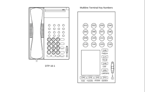
3. MULTILINE TERMINAL/SN610 ATTCON/SN716 DESKCON/DSS CONSOLE/ADD-ON MODULE KEY ASSIGNMENT
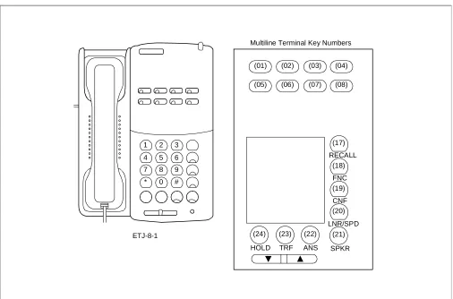
Figures 1-1 through 1-5 show the key number of each Multiline Terminal, SN610 ATTCON, SN716 DESKCON, DSS Console and Add-On Module. Refer to this section when performing a key assignment by CM90 or CM97 in FEATURE PROGRAMMING.
Figure 1-1 Multiline Terminal Key Numbers
1 2 3
4 5 6
7 8 9
* 0 #
(01)
RECALL
FNC
CNF
LNR/SPD
SPKR ANS
TRF HOLD ETJ-8-1
Multiline Terminal Key Numbers
(05) (02) (06)
(03) (07)
(04) (08)
(17)
(18)
(19)
(20)
(21) (22)
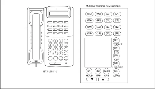
ND-45670 (E) CHAPTER 1 Page 3 Revision 2.0 Figure 1-1 Multiline Terminal Key Numbers (Continued)
1 2 3
4 5 6
7 8 9
* 0 #
(01)
RECALL
FNC
CNF
LNR/SPD
SPKR ANS
TRF HOLD ETJ-16DC-1
Multiline Terminal Key Numbers
(05) (02) (06)
(03) (07)
(04) (08)
(17)
(18)
(19)
(20)
(21) (22) (23) (24)
(09) (13)
(10) (14)
(11) (15)
INTRODUCTION
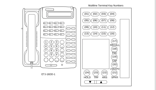
Figure 1-1 Multiline Terminal Key Numbers (Continued)
1 2 3
4 5 6
7 8 9
* 0 #
RECALL
FNC
CNF
LNR/SPD
SPKR ANS
TRF HOLD ETJ-16DD-1
Multiline Terminal Key Numbers
(01) (05)
(09) (13)
(02) (06)
(10) (14)
(03) (07)
(11) (15)
(04) (08)
(12) (16)
(17)
(18)
(19)
(20)
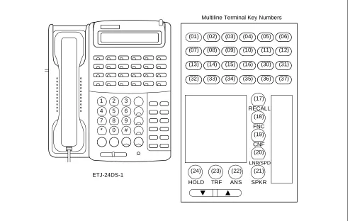
ND-45670 (E) CHAPTER 1 Page 5 Revision 2.0 Figure 1-1 Multiline Terminal Key Numbers (Continued)
Note: Key numbers 30 through 37 require Add-On Module key assignment. (For details, see “Proprietary Multi-line Terminal” feature in Chapter 2).
1 2 3
4 5 6
7 8 9
* 0 #
RECALL
FNC
CNF
LNR/SPD
SPKR ANS
TRF HOLD ETJ-24DS-1
Multiline Terminal Key Numbers
(01) (07) (13) (32)
(02) (08) (14) (33)
(03) (09) (15) (34)
(04) (10) (16) (35)
(05) (11) (30) (36)
(06) (12) (31) (37)
(17)
(18)
(19)
(20)
INTRODUCTION
Figure 1-1 Multiline Terminal Key Numbers (Continued)
Multiline Terminal Key Numbers
Recall Feature
CNF
LNR/SPD
Speaker Answer Transfer Hold
(19) (17) (18)
(20) (03) (04) (01) (02)
(05) (06) (07) (08)
(21) (22) (23) (24)
1 4 7
2 5 8 0 # *
9 6 3
NEC
ND-45670 (E) CHAPTER 1 Page 7 Revision 2.0 Figure 1-1 Multiline Terminal Key Numbers (Continued)
Multiline Terminal Key Numbers
Speaker Answer Transfer Hold
(03) (04) (01) (02)
(05) (06) (07) (08)
Recall
(17)
CNF
(19)
LNR/SPD
(20)
(21) (22) (23) (24)
Feature
(18)
1 4 7
2 5 8 0 #
9 6 3
NEC
INTRODUCTION
Figure 1-1 Multiline Terminal Key Numbers (Continued)
1 4 7
2 5
0 # *
3 NEC
DTP-16-1
Multiline Terminal Key Numbers
Speaker Answer Transfer Hold
(07) (08) (05) (06)
(11) (12) (09) (10)
(15) (16) (13) (14)
(03) (04) (01) (02)
Recall
(17)
CNF
(19)
LNR/SPD
(20)
(21) (22) (23) (24)
Feature
(18)
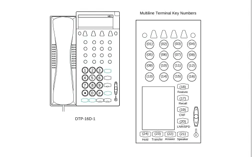
ND-45670 (E) CHAPTER 1 Page 9 Revision 2.0 Figure 1-1 Multiline Terminal Key Numbers (Continued)
Multiline Terminal Key Numbers
Speaker Answer Transfer Hold
(07) (08) (05) (06)
(11) (12) (09) (10)
(15) (16) (13) (14)
(03) (04) (01) (02)
Recall
(17)
CNF
(19)
LNR/SPD
(20)
(21) (22) (23) (24)
Feature
(18)
1 4 7
2
8 0 #
9 6 3
NEC
INTRODUCTION
Figure 1-1 Multiline Terminal Key Numbers (Continued)
Note: Key numbers 30 through 37 can be used as either Line/Trunk/Feature key or DSS key. In other words:
• Line/Trunk key, Feature key =16 + DSS key =16 or
• Line/Trunk key, Feature key =24 + DSS key =8
When key numbers 30 through 37 are used as the Line/Trunk/Feature keys, the Add-on Module key assign-ment is required. (For details, see “Proprietary Multiline Terminal” feature in Chapter 2).
Recall Feature
CNF
LNR/SPD
Speaker Answer Transfer Hold
(19) (17) (18)
(20) (03) (04) (01) (02)
(05) (06) (07) (08)
(09) (10) (11) (12)
(13) (14) (15) (16)
(21) (22) (23) (24)
(30)
(32)
(34)
(36) (31)
(33)
(35)
(37)
1 4 7
2 5 8 0 # *
9 6 3
NEC
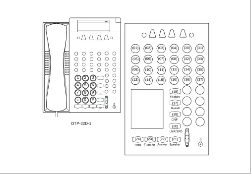
ND-45670 (E) CHAPTER 1 Page 11 Revision 2.0 Figure 1-1 Multiline Terminal Key Numbers (Continued)
Note: Key numbers 30 through 37 can be used as either Line/Trunk/Feature key or DSS key. In other words:
• Line/Trunk key, Feature key =16 + DSS key =16 or
• Line/Trunk key, Feature key =24 + DSS key =8
When key numbers 30 through 37 are used as the Line/Trunk/Feature keys, the Add-on Module key assign-ment is required. (For details, see “Proprietary Multiline Terminal” feature in Chapter 2).
1 4 7
2 5 8 0 # *
9 6 3
NEC
Recall Feature
CNF
LNR/SPD
Speaker Answer Transfer Hold
(19) (17) (18)
(20) (03) (04) (01) (02)
(05) (06) (07) (08)
(09) (10) (11) (12)
(13) (14) (15) (16)
(21) (22) (23) (24)
(30)
(32)
(34)
(36) (31)
(33)
(35)
(37)
INTRODUCTION
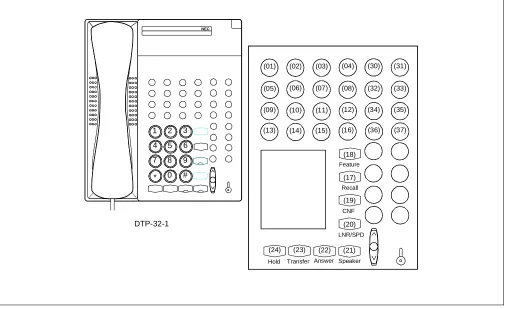
Figure 1-2 SN610 ATTCON Key Numbers
Note: The key No. 30-37 can be used as either Line/Trunk/Feature key or DSS key. In other words:
• Line/Trunk key, Feature key × 16 + DSS key × 16 or
• Line/Trunk key, Feature key × 24 + DSS key × 8
When the key No. 30-37 is used as the Line/Trunk/Feature key, the Add-on Module Data assignments for these keys are required, according to the same method as the ETJ-24DS-1 (Multiline Terminal providing 24 Line/Trunk keys).
1 2 3 4 5 6 7 8 9 0 #
Speaker
(01)
Feature
Hold Transfer Answer Redial
Conf Recall
(06) (05) (04) (03) (02)
(12)
(31)
(37)
(07) (08) (09) (10) (11)
(13) (14) (15) (16) (30)
(32) (33) (34) (35) (36)
(18)
(17)
(19)
(20)
(21) (22) (23) (24)
DTP-32-1
ND-45670 (E) CHAPTER 1 Page 13 Revision 2.0 Figure 1-3 SN716 DESKCON Key Numbers
EMG BV TRKSL Call Pack SC SVC LDN TIE Busy ATND NANS Recall (13) (14) (15) (16) (17) (18) (21)
(01) (02) (03) (04)
PAGE REC Start Mute
Night Position Busy
Volume
DEST
Answer
(20)
(25) DEST Cancel
(24)
Talk (22)
Hold
(23) (26)
Release
(19) SRC
1 2 3
4 5 6
7 9
0 8 L6 (12)
L5 (11)
L4 (10)
L3 (09)
L2 (08)
INTRODUCTION
Figure 1-4 DSS Console Key Numbers
00 01 02 03 04 05 06 07
08 09 10 11 12 13 14 15
16 17 18 19 20 21 22 23
24 25 26 27 28 29 30 31
32 33 35 36 37 38 39
40 41 42 43 44 45 46 47
48 49 50 51 52 53
54 55 56 57 58 59
EDW-48-2
ND-45670 (E) CHAPTER 1 Page 15 Revision 2.0 Figure 1-4 DSS Console Key Numbers (Continued)
00
06
12
18
24
30
36
42
48
54 55 56 57 58 59 49 50 51 52 53 43 44 45 46 47 37 38 39 40 41 31 32 33 34 35 25 26 27 28 29 19 20 21 22 23 13 14 15 16 17 07 08 09 10 11 01 02 03 04 05
INTRODUCTION
Figure 1-5 Add-On Module Key Numbers
30 31 32 33 34 35 36 37
38 39 40 41 42 43 44 45
46 47 48 49 50 51 52 53
54 55 56 57 58 59 60 61
62 63 64 65 66 67 68 69
70 71 72 73 74 75 76 77
78 79 80 81 82 83
84 85 86 87 88 89
ND-45670 (E) CHAPTER 1 Page 17 Revision 2.0 Figure 1-5 Add-On Module Key Numbers (Continued)
30
36
42
48
54
60
66
72
78
84 85 86 87 88 89 79 80 81 82 83 73 74 75 76 77 67 68 69 70 71 61 62 63 64 65 55 56 57 58 59 49 50 51 52 53 43 44 45 46 47 37 38 39 40 41 31 32 33 34 35
INTRODUCTION
ND-45670 (E) CHAPTER 2 Page 19 Revision 2.0
1. GENERAL
This section provides the description for programming each service feature.
2. DESCRIPTION OF SERVICE FEATURES
The description of each service feature comprises the following items:
• PROGRAMMING
This section provides the procedures for programming the service feature. If the service feature is function-ing in conjunction with other features, refer to the sections containfunction-ing the information pertainfunction-ing to those features.
In the programming procedure, the meaning of (1), (2), and the icons are as follows:
(1) : 1st Data
(2) : 2nd Data
: Initial Data
With the system data clear command (CM00, CM01), the data with this marking ( ) is automatically as-signed for each command.
: System Initialization
: After entering the data, system reset is required (press SW1 on the MP card).
• HARDWARE REQUIRED
In this section, any hardware required for the feature (such as an interface card or external drive) is listed, with the exception of the following:
(a) Single-line telephone set and interface card (PN-4LC) (b) Central Office Trunk Card (PN-4COT)
Note: For Series E Multiline Terminals (DTP-8-1, DTP-8D-1, DTP-16-1, DTP-16D-1, DTP-32-1, DTP-32D-1), the feature programming is available in same method as the Series III Multiline Terminal. However, when the Series E Multiline Terminal with Series III mode or the Elite Terminal is accommodated, it is necessary to specify the kind of the terminal accommodated in a DLC card by programming of CM12 Y= 17. Refer to “Proprietary Multiline Terminal” for the programming of CM12 YY = 17.
The feature programming for SN716 DESKCON is available in same method as the SN610 ATTCON. However, it is necessary to specify the type of console by programming of CM60 YY=22. Refer to “SN716 DESKCON” for programming related to SN716 DESKCON.
ACCOUNT CODE
2.1 Business Features
PROGRAMMING
HARDWARE REQUIRED
SMDR (PN-AP00 card and cables)
DESCRIPTION DATA
Specify whether Service Set Tone should be sent after dialing the access code for Account Code entry.
(1) 362
(2) 0/1 : No Tone/Service Set Tone (SST)
Assign the Class of Service for Account Code entry to the required stations.
• CM12 YY = 02
(1) X-XXXX: Primary Extension No. (2) XX XX
*a: Service Restriction Class (A): 00-15
• CM15 YY = 30
(1) 00-15 : Service Restriction Class (A) assigned by CM12 YY = 02 (2) 1 : Allowed
Specify the maximum number of digits for Account Codes.
Note: If the SMDR message format (2400 IMS Format) is assigned, the maxi-mum number of digits is 10. (See CM D001-82/102/122 in the SMDR Sys-tem Manual.)
(1) 10 : Max. number of digits for Ac-count Codes
(2) 01-16 : Max. number of digits If no data is entered, the default is 10.
Assign an access code for Account Code en-try.
• Y = 0-3: Numbering Plan Group 0-3 (1) X-XXX: Access Code (* #) (2) 085
Assign an Account Code feature access key to a Multiline Terminal.
• YY = 00
(1) Primary Extension No. + + Key No. (2) F0085
CM08 START
END CM42
CM20
CM90 CM12
CM15 *a
ND-45670 (E) CHAPTER 2 Page 21 Revision 2.0
PROGRAMMING
DESCRIPTION DATA
Assign the Add-On Module Number to its associated LEN.
Note: When the data assignment of both DSS Console and Add-On Module are required, the same number (the last two digits of the data) cannot be used.
(1) 0000-0511 (LEN No.)
(2) EC00-EC31: Add-On Module No. For PIM0/1: EC00-EC07
For PIM2/3: EC08-EC15 For PIM4/5: EC16-EC23 For PIM6/7: EC24-EC31
Assign the Multiline Terminal which will be associated with the Add-On Module.
Note: The Multiline Terminal and the Add-On Module must be in the same PIM (Port Interface Module).
• Y=0
(1) 00-31 (Add-On Module No.: Last two digits of EC00-EC31 assigned by CM10.)
(2) X-XXXX (Primary Extension Number) Note
Assign the Class of Service for the
accommodation of Single-Line Telephone to Multiline Terminal. (Assignment for Single-Line Telephone only).
• YY=05
(1) X-XXXX: Station No. (2) 0: Accommodated
Assign the station and trunk numbers to the keys on each Add-On Module.
Note: Single-Line, Virtual Line or Primary Extension can be assigned on Add-On Module.
• YY=00
(1) Primary Extension No. + + Add-On Module Key No. (30-54)
(2) X-XXXX (Station No.) Note DXXX
*a
*a: 000-255 (Trunk No.) START
CM10
A CM12
CM90 CM98
Note
ADD-ON MODULE (1200 Series Enhancement)
PROGRAMMING
DESCRIPTION DATA
Assign the Automatic/Manual/Dial Intercom key to each Add-On Module, if required. For details, refer to INTERCOM.
• YY=00
(1) Primary Extension No. + + Add-On Module Key No. (30-54)
(2) A000
A031 Automatic Intercom No. A100
A131 A200
A700 A201
A701 Manual Intercom No.
A224
A724 B000
B900 B001
B901 Dial Intercom No.
B024
B924
Assign the Station Speed Dialing to the keys on each Add-On Module, if required. For details, refer to STATION SPEED DIALING.
• YY=00
(1) Primary Extension No. + + Add-On Module Key No. (30-89)
(2) F11XX *a
*a: 00: Station Speed Dialing 00
99: Station Speed Dialing 99 CM90
A
B
,
ND-45670 (E) CHAPTER 2 Page 23 Revision 2.0
HARDWARE REQUIRED
DSS Console
PN-2DLC/4DLC Card (Two or four DSS Console can be accommodated per card)
DESCRIPTION DATA
Assign the Day/Night Key on each Add-On Module, if required.
• YY=00
(1) Primary Extension No. + + Add-On Module Key No. (87-89)
(2) F0043: Day/Night Key
Specify the tone ringer enabled on call termination to each line/trunk key on each Add-On Module, if required.
• YY=01
(1) Primary Extension No. + + Add-On Module Key No. (30-54)
(2) 0/1 : Disabled/Enabled
Assign the Delayed Ringing feature to each line/trunk key on an Add-On Module, if required.
Note: Delayed Ringing can be assigned to the first 16 line/trunk keys (Key No. 30-45).
• YY=03
(1) Primary Extension No. + + Add-On Module Key No. (30-45) Note
(2) 0: Delayed Ringing
Specify the Delayed Ringing timing. • Y=1 (1) 09
(2) 01-20: Timer Data for 2 sec. - 40 sec. (2 sec. increment)
If no data is set, the default setting is 10 seconds.
Provide Trunk-Direct Appearances to the trunk number.
• YY=18
(1) Trunk No. (000-255) (2) 0: To be provided CM90
B
END CM41
CM30
,
,
ALPHANUMERIC DISPLAY
PROGRAMMING
DESCRIPTION DATA
Provide the system with the Name Display Service.
(1) 255
(2) 1 : To be provided
Station number and number display provided when an incoming call terminates to a Prime Line and a Primary Extension.
(1) 335
(2) 1 : To be provided
Assign the access code for station user name entry (used from individual stations).
• Y= 0-3 (Numbering Plan Group 0-3) (1) X-XXX: Access Code (62)
(2) A10
Assign a Trunk Name Number to each Trunk Route.
• YY = 03
(1) 00-63 : Trunk Route No. (2) 00 : Trunk Name No. 00
14 : Trunk Name No. 14
15 : Kind of Trunk Route assigned by CM35 YY = 00 is displayed 16 : Trunk Name No.16
63 : Trunk Name No. 63
Assign the desired station user’s name to each station number by Y = 0 or Y = 1.
• Y = 0 (By Character Code) (1) X-XXXX: Station No. (2) Character Code
(20-7F:See Character Code Table Max. 16 digits)
• Y = 1 (By Character) (1) X-XXXX: Station No.
(2) Character (A-Z, 0-9) Max. 8 characters CM08
CM20 START
A CM35
ND-45670 (E) CHAPTER 2 Page 25 Revision 2.0 Note 1: The maximum number of stations that can be provided with the user’s name display is 384. The maximum number of characters per name is eight, including spaces. The Maintenance Administration Terminal (MAT) or Customer Administration Terminal (CAT) can be used to register or change a name. A Multiline Terminal can register or change the name assignment of that individual Multiline Terminal.
Note 2: User names can be assigned to stations that do not have an LCD.
Note 3: The trunk name display is provided on a trunk-route basis. The maximum amount of characters in the trunk name display is four. The maximum number of trunk routes assignable is 16. The MAT or CAT can be used to register or change a trunk name display.
Note 4: There are two ways to change a name that is currently programmed. (1) by overwriting with a new name, or (2) by inserting a blank space as the first character to cancel the existing name.
DESCRIPTION DATA
Assign the desired trunk name to each trunk route by Y = 2 or Y = 3.
• Y = 2 (By Character Code)
(1) 00-14, 16-63:Trunk Name No. assigned by CM35 YY = 03.
(2) Character Code
20-7F: See Character Code Table Max. 8 digits
• Y = 3 (By Character)
(1) 00-14, 16-63: Trunk Name No. assigned by CM35 YY = 03. (2) Character Code (A-Z, 0-9) Max. 4
char-acters END
ALPHANUMERIC DISPLAY
Character Code Table
2
3
4
5
6
7
0
0
@
P
\
p
1
!
1
A
Q
a
q
2
”
2
B
R
b
r
3
#
3
C
S
c
s
4
$
4
D
T
d
t
5
%
5
E
U
e
u
6
&
6
F
V
f
v
7
’
7
G
W
g
w
8
(
8
H
X
h
x
9
)
9
I
Y
i
y
A
*
:
J
Z
j
z
B
+
;
K
[
k
{
C
,
<
L
¥
l
|
D
-
=
M
]
m
}
E
.
>
N
^
n
→
F
/
?
O
_
o
←
ND-45670 (E) CHAPTER 2 Page 27 Revision 2.0
PROGRAMMING
To assign the Single Port Mode:
To assign the Dual Port Mode:
1. Data Assignment for Multiline Terminal accommodates the Analog Port Adapter.
DESCRIPTION DATA
Provide the Analog Port Adapter to the required stations.
• YY=32
(1) X-XXXX: Primary Extension No. (2) 0: To be provided
Assign the Single Port Mode to the required stations.
• YY=33
(1) X-XXXX: Primary Extension No. (2) 1 : Single Port Mode
Specify whether a ringing signal is sent to the Analog terminal.
• YY=35
(1) X-XXXX: Primary Extension No. (2) 0/1 : Not to be sent/To be sent
DESCRIPTION DATA
Provide the Analog Port Adapter to the required stations.
• YY=32
(1) X-XXXX: Primary Extension No. (2) 0: To be provided
Assign the Dual Port Mode to the required stations.
• YY=33
(1) X-XXXX: Primary Extension No. (2) 0: Dual Port Mode
START
CM13
END
START
CM13
END
ANALOG PORT ADAPTER (1200 Series Enhancement)
2. Data Assignment for Analog Terminal connected to the Analog Port Adapter. .
DESCRIPTION DATA
Assign an Analog Terminal Station No. to the required LEN.
(1) LEN (0000-0511)
(2) FX-FXXXX: Analog Terminal Station No.
Note: The Analog Terminal Station No. must be assigned to the LEN of right side LT slot to the LT slot for DLC.
Example: When the DLC card is mounted in the LT01 slot and LT03 slot.
Assignment Example:
CM 10 - LEN 0000 = F 200 for Dterm Primary
Extension
LEN 0004 = F 300 for Analog Terminal
If level 0 of the LEN is used for the Dterm,
the adjacent level 0 must be used. START
A CM10
LT00 LT01 LT02 LT03 LT04
D L C
D L C
LT slot for assigning an Analog Terminal Station No.
ND-45670 (E) CHAPTER 2 Page 29 Revision 2.0
DESCRIPTION DATA
Assign a key for Analog Terminal. • YY=00
(1) Analog Terminal Station No. + + Key No.
(2) X-XXXX: Analog Terminal Station No. assigned by CM10.
Assign an Analog Terminal Station No. as Prime Line.
(1) X-XXXX: Analog Terminal Station No. (2) X-XXXX: Analog Terminal Station No.
Provide the Analog Port Adapter to the required station.
• YY=34
(1) X-XXXX: Analog Terminal Station No. (2) 0: To be provided
Specify whether a ringing signal is sent to the Analog Terminal.
• YY=35
(1) X-XXXX: Primary Extension No. (2) 0/1 : Not to be sent/To be sent
Specify the PAD control of the Analog Terminal.
• YY=09
(1) X-XXXX: Analog Terminal Station No. (2) 0/1 : Not Available/Available
CM90
CM93
CM13
END A
ANNOUNCEMENT SERVICE
PROGRAMMING
DESCRIPTION DATA
Specify the Multi-Connection of the Digital Announcement Trunk (PN-2DATA) on Announcement Service.
(1) 124
(2) 0/1 : Available/Not Available (Single Connection)
Assign a Digital Announcement Trunk Circuit No. to the required LEN.
Note: The Digital Announcement Trunk Circuit No. must be assigned to the first LEN (Level 0) and/or the third LEN (Level 2) of each LT slot.
(1) LEN (0000-0511)
(2) EB000-EB127: Digital Announcement Trunk Circuit No. For PIM0/1: EB000-EB031 For PIM2/3: EB032-EB063 For PIM4/5: EB064-EB095 For PIM6/7: EB096-EB127
• CM12 YY = 02
(1) X-XXXX: Primary Extension No. (2) XX XX
*a: Service Restriction Class (A): 00-15
• CM15 YY = 34 (Group 0) • CM15 YY = 35 (Group 1) • CM15 YY = 36 (Group 2) • CM15 YY = 37 (Group 3) • CM15 YY = 38 (Group 4)
• CM15 YY = 39 [Recording for An-nouncement Service (Group 0-4)] (1) 00-15 : Service Restriction Class (A)
assigned by CM12 YY = 02 (2) 1 : Allowed
Assign access codes for Announcement Service.
• Y = 0-3 (Numbering Plan Group 0-3) (1) X-XXX: Access Code
(2) A03: Recording message (Group 0-4) A04: Replaying message (Group 0) A05: Replaying message (Group 1) A06: Replaying message (Group 2) A07: Replaying message (Group 3) A08: Replaying message (Group 4) A09: Deleting message (Group 0-4) CM08
CM10 START
A CM20 CM12
ND-45670 (E) CHAPTER 2 Page 31 Revision 2.0 Note 1: A maximum of five different announcements can be accessed. There is a limit of 10 Digital Announcement Trunk Circuit for each of the five different announcements. When recording an announcement, each Digital Announcement Trunk Circuit must be recorded individually.
Note 2: Each time a station is connected to a Digital Announcement Trunk Circuit, the message will be repeated three times. The station will then be disconnected.
Note 3: For the single connection of a Digital Announcement Trunk Circuit, the duration of an announcement is limited to 60 seconds.
Note 4: For the multi-connection of a Digital Announcement Trunk Circuit, the duration of replay for an announce-ment is programmable from 4 to 396 seconds.
DESCRIPTION DATA
When multi-connection is provided (CM08124 = 0), specify the duration of message replay for Announcement Service.
• Y = 0 (1) 53
(2) 01-99: 4-396 sec. in 4 sec. increments If no data is set, the default setting is 60-64 seconds.
Assign the function for each Digital Announcement Trunk.
• YY = 00
(1) 000-127: Digital Announcement Trunk Circuit No. assigned by CM10 (EB000-EB127)
(2) 04X X
*a: Group No. (0-4) *b: Message No. (0-9)
To provide a Tie Line party with this service, assign the Announcement Service Group 0-4 to the required Trunk Routes.
• YY = 69 (Group 0) • YY = 70 (Group 1) • YY = 71 (Group 2) • YY = 72 (Group 3) • YY = 73 (Group 4) (1) 00-63 : Trunk Route No. (2) 1 : Allowed
END CM41
A
CM49
CM35
ANNOUNCEMENT SERVICE
To provide a voice message when an incoming C.O. line/Tie line call has been transferred and encounters a busy or no answer condition:
DESCRIPTION DATA
Assign a Digital Announcement Trunk Circuit No. to the required LEN.
Note: The Digital Announcement Trunk Circuit No. must be assigned to the first LEN (Level 0) and/or the third LEN (Level 2) of each LT slot.
(1) LEN (0000-0511)
(2) EB000-EB127: Digital Announcement Trunk Circuit No. For PIM0/1: EB000-EB031 For PIM2/3: EB032-EB063 For PIM4/5: EB064-EB095 For PIM6/7: EB096-EB127
Assign the feature for a voice message connection to a transferred trunk when the transferred destination does not answer or the transferred destination is busy to the required tenant.
• YY = 50 (No Answer) (1) 00-63: Tenant No. (2) 0
• YY = 51 (Busy) (1) 00-63: Tenant No. (2) 0
Assign the function for each Digital Announcement Trunk.
• YY = 00
(1) 000-127: Digital Announcement Trunk Circuit No. assigned by CM10 (EB000-EB127)
(2) 06XX: No Answer
*a: Message No. (00-63)
07XX: Busy
*a: Message No. (00-63) • YY = 06 (No Answer) • YY = 07 (Busy)
(1) 00-63: Tenant No. of transferring station (2) 00-63: Message No. assigned by YY =
00
To record, replay, or delete a message, assign the respective Digital Announcement Trunk access code.
• Y = 0-3 (Number Plan Group 0-3) (1) X-XXX: Access Code
(2) A00: Record A01: Replay A02: Delete CM10
START
END CM65
CM49
CM20
*a
ND-45670 (E) CHAPTER 2 Page 33 Revision 2.0 Note 5: Announcement Service can be used to provide a voice message when an incoming C.O. line/Tie line call has been transferred and encounters a busy or no answer condition. After the voice message is given, nor-mal call processing continues.
- This application can be programmed on a tenant basis.
- Only one (1) message of up to 60 seconds can be recorded on an individual Digital Announcement Trunk Circuit.
- In this application, a minimum of two digital announcement Trunk Circuits are needed, one for busy condition, and one for no answer.
- More than one Digital Announcement Trunk Circuit can be used, depending on traffic conditions.
- System programming can be set to, wait until circuit(s) become free or immediately follow prepro-grammed normal call handling, if a busy condition is encountered.
- Digital Announcement Trunk Circuits can be shared among tenants.
ANNOUNCEMENT SERVICE
To provide an Internal Recorded Message from a Digital Announcement Trunk (PN-2DATA) in place of Music On Hold:
DESCRIPTION DATA
Assign a Digital Announcement Trunk Circuit No. to the required LEN.
Note: The Digital Announcement Trunk Circuit No. must be assigned to the first LEN (Level 0) and/or the third LEN (Level 2) of each LT slot.
(1) LEN (0000-0511)
(2) EB000-EB127: Digital Announcement Trunk Circuit No.
For PIM0/1: EB000-EB031 For PIM2/3: EB032-EB063 For PIM4/5: EB064-EB095 For PIM6/7: EB096-EB127
Define the type of call to be provided with Hold Message.
• Y = 0
(1) 00: C.O. Line Call 01: Tie Line Call 02: Internal Call (2) 0500: Hold Message
Assign the function of the Digital Announcement Trunk to Hold Message Service.
• YY = 00
(1) 000-127 : Digital Announcement Trunk Circuit No. assigned by CM10 (EB000-EB127)
(2) 05XX : For Hold Message Service
*a: Message No. (00-63)
• YY = 05
(1) 00-63: Tenant No.
(2) 00-63: Message No. assigned by YY = 00
To record, replay, or delete a message, assign the respective Digital Announcement Trunk access code.
• Y = 0-3 (Number Plan Group 0-3) (1) X-XXX (Access Code)
(2) A00: Record A01: Replay A02: Delete CM10
START
END CM48
CM49
CM20
ND-45670 (E) CHAPTER 2 Page 35 Revision 2.0 Note 6: A voice message in place of Music-On-Hold can be provided when a call has been placed on hold.
- Different messages can be programmed on a tenant basis.
- Different messages can be programmed, depending on the type of line (CO line, Tie line or station) on Hold.
- More than one connection can be made to a Digital Announcement Trunk Circuit. Only the first connec-tion can be assured of hearing the message from the beginning.
ANNOUNCEMENT SERVICE
To provide the Night Announcement by Digital Announcement Trunk (PN-2DATA)
DESCRIPTION DATA
Assign each Digital Announcement Trunk Circuit No. to the required LEN.
Note: The Digital Announcement Trunk Circuit No. must be assigned to the first LEN (Level 0) and/or the third LEN (Level 2) of each LT slot.
(1) LEN (0000-0511)
(2) EB000-EB127: Digital Announcement Trunk Circuit No.
For PIM0/1: EB000-EB031 For PIM2/3: EB032-EB063 For PIM4/5: EB064-EB095 For PIM6/7: EB096-EB127
Assign the Digital Announcement Trunk Circuit No. to each incoming trunk.
• YY = 03
(1) 000-255: Trunk No. (2) 04: Direct-In Termination
• YY = 05
(1) 000-255 : Trunk No.
(2) EB000-EB127 : Digital Announcement Trunk Circuit No. assigned by CM10.
Assign the function of the Digital Announcement Trunk to Night Announcement.
• YY = 00
(1) 000-127 : Digital Announcement Trunk Circuit No. assigned by CM10. (EB000-EB127)
(2) 03000 : For Night Announcement Ser-vice
Specify the duration of a Night Announcement.
• Y = 0 (1) 45
(2) 01-99: 4 -396 sec. in 4sec. increments If no data is set, the default setting is 60-64 seconds.
To record, replay, or delete a message, assign the respective Digital Announcement Trunk Circuit access code.
• Y = 0-3 (Numbering Plan Group 0-3) (1) X-XXX: Access Code
(2) A00: Record A01: Replay A02: Delete CM10
START
END CM30
CM49
CM41
ND-45670 (E) CHAPTER 2 Page 37 Revision 2.0 Note 7: A voice message can be sent to incoming C.O. lines during night mode.
- Different messages can be programmed on each C.O. line.
- The voice message can be programmed for day/night.
- More than one connection can be made to a Digital Announcement Trunk Circuit. Only the first con-nection can be assured of hearing the message from the beginning.
- Announcements may be programmed to be repeated from 4 to 120 seconds in four-second increments.
HARDWARE REQUIRED
ANSWER KEY
PROGRAMMING
Note: An ANSWER key is initially assigned on each Multiline Terminal. HARDWARE REQUIRED
ETJ-8-1/ETJ-16DC-1/ETJ-16DD-1/ETJ-24DS-1 and PN-2DLCB/PN-4DLCA card.
DESCRIPTION DATA
Assign the Class of Service for this feature to the required Multiline Terminals.
• CM12 YY = 02
(1) X-XXXX: Primary Extension No. (2) XX XX
*a: Service Restriction Class (B): 00-15
• CM15 YY = 72
(1) XX : Service Restriction Class (B) as-signed by CM12 YY = 02
(2) 0 : Allowed START
END CM12
ND-45670 (E) CHAPTER 2 Page 39 Revision 2.0
PROGRAMMING
DESCRIPTION DATA
Assign the Access code for an operator call. • Y = 0-3 (Numbering Plan Group 0-3) (1) X-XXX: Access Code (0)
(2) 800
Allocate the ATTCON Group No. to each SN610 ATTCON.
• YY = 00
(1) 0-7: ATTCON No. assigned by CM10. (2) 0-3: ATTCON Group No.
Assign the Master ATTCON within the ATTCON Group.
• YY = 01
(1) 0-7: ATTCON No. (2) 0/1 : Master/Sub
Specify the tenants to be handled by each ATT Group.
• Y = 0-3 (ATTCON Group No.0-3 as-signed by CM60 YY = 00)
(1) 00-63 : Tenant No. (2) 0 : To be handled
Specify the Attendant access (ATTCON No. 0) capability provided from the stations belonging to a tenant with no SN610 ATTCON.
(1) 142
(2) 0/1 : Allowed/Restricted
Provide the system with Passing Dial Tone. (1) 048
(2) 1 : To be provided
Provide the system with Attendant Night Transfer, if required.
(1) 018
(2) 0/1 : Not to be provided/Provided
Specify the Individual Attendant access capability provided from a station belonging to a different tenant.
(1) 143
(2) 0/1 : Restricted/Allowed CM20
START
END CM60
CM62
CM08
INITIAL
ATTENDANT CAMP-ON
PROGRAMMING
To reenter a Camped-On trunk from an Attendant before Automatic Recall (1200 Series Enhancement):
To display the busy station number and name on an Attendant Console when reentering a Camped-On trunk by de-pressing the loop key (1200 Series Enhancement):
DESCRIPTION DATA
Specify the Camp-On Tone sent to busy station.
(1) 068
(2) 0 : Camp-on Tone is sent out only once. 1 : Camp-on Tone is repeated at an
interval of 4 seconds.
Specify the recall timing of Camp-On. • Y = 0 (1) 00
(2) 01-14: 2.4-33.6 sec. in 2.4 sec. increments
15-24: 38.4-124.8 sec. in 9.6 sec. increments
If no data is set, the default setting is 31.2-33.6 seconds.
DESCRIPTION DATA
Assign the access code for Call Pickup - Direct.
• Y=0-3 (Numbering Plan Group 0-3) (1) X-XXX: Access Code
(2) 021: Call Pickup - Direct
DESCRIPTION DATA
Provide the SN610 ATTCON with the busy station number/name display when reentering a Camped-On trunk.
(1) 441
(2) 0: To be provided 1 : Not to be provided START
END CM08
CM41
START
END CM20
START
ND-45670 (E) CHAPTER 2 Page 41 Revision 2.0
PROGRAMMING
DESCRIPTION DATA
Assign the card number of the interface circuit for the SN610 ATTCON to its associated LEN.
(1) 0000-0511 : LEN No. (2) E000-E007 : ATTCON No.
Set the terminating system for the incoming calls to SN610 ATTCON.
• YY = 02 (Day mode), YY = 03 (Night mode)
(1) Trunk No. (000-255)
(2) 14: Termination to SN610 ATTCON
Assign the required Attendant Call Selection keys and ATTCON Function keys to each SN610 ATTCON.
If no data is set, the default setting is as follows (Refer to MULTI-FUNCTION KEY for assignment of Multi-Function Keys).
• YY = 00
(1) ATTCON No. (E000-E007) + + Key No.
(2) F6000-F6067: Type of Calls to be as-signed
F6100-F6245: Functions to be assigned CM10
CM30 START
A
ATTENDANT CONSOLE (SN610 ATTCON)
DESCRIPTION DATA
Note: ANS or RLS keys can be assigned on either 25 or 26 by CM60 YY = 15.
Allocate the ATT Group No. to each SN610 ATTCON.
• YY = 00
(1) ATTCON No. (0-7) (2) 0: ATT GROUP 0
3: ATT GROUP 3 Specify the Master SN610 ATTCON within
the ATT Group assigned by YY = 00.
• YY = 01
(1) ATTCON No. (0-7) (2) 0/1 : Master/Sub
Specify the location of Answer (ANS) and Release (RLS) key.
• YY = 15
(1) ATTCON No. (0-7)
(2) 0 : Key No.25-Release, Key No.26-An-swer
1 : Key No.25-Release, Key No.26-Answer
Specify the tenants to be handled by each ATT Group.
• Y = 0-3
(1) Tenant No. (00-63)
(2) 0/1 : To be handled/Not to be handled
END A
CM62 CM60
Key No. Data Description
01 F6110 Mode (MODE)
02 F6111 Programming (PROG)
07-12 F6240-F6245 Loop 1-Loop 6
16 F6061 Re-Call (RCL)
17 F6060 Operator Call (ATND)
18 F6000 C.O. Incoming 0
(LDN0)
19 F6200 Source (SRC)
20 F6201 Destination (DEST)
23 F6204 Hold (HOLD)
24 F6202 Cancel (CANCEL)
25 Note Answer (ANS)
26 Note Release (RLS) LO O P1 LO O P2 LO O P3 LO O P4 LO O P5 LO O P6
0 1
AN S
2 5
R LS
2 6 1 2 3 4 5 6 7 8 9 * 0 #
S RC D ES T
H O LD C ANC EL M O DE PRO G
1 3 1 4 1 5 1 6 1 7 1 8
1 9 2 0 2 1 2 2 2 3 2 4 0 7
0 2 0 3 0 4 0 5 0 6 0 8 0 9 1 0 1 1 1 2
ABC D EF JKL M NO G H I
TUV WX Y PRS
O PER
| |
INITIAL
ND-45670 (E) CHAPTER 2 Page 43 Revision 2.0
PROGRAMMING
DESCRIPTION DATA
Provide the system with the Name Display Service.
(1) 255
(2) 1 : To be provided
Assign the access code for station user name entry, used from individual stations.
• Y = 0-3 (Numbering Plan Group 0-3) (1) X-XXX: Access Code (62)
(2) A10
Assign a Trunk Name Number to each Trunk Route.
• YY = 03
(1) 00-63 : (Trunk Route No.) (2) 00 : Trunk Name No. 00
14 : Trunk Name No. 14
15 : Kind of Trunk Route assigned by CM35 YY = 00 is displayed 16 : Trunk Name No. 16
63 : Trunk Name No. 63 Assign the desired station user name to each
station number by Y = 0 or Y = 1.
• Y = 0 (By Character Code) (1) X-XXXX: Station No. (2) Character Code
(20-7F: See Character Code Table) Max. 16 digits
• Y = 1 (By Character) (1) X-XXXX: Station No. (2) Character (A-Z, 0-9)
Max. 8 characters Assign the desired trunk name to each trunk
route by Y = 2 or Y = 3.
• Y = 2 (By Character Code)
(1) 00-14, 16-63 (Trunk Name No. assigned by CM35 YY = 03.)
(2) Character Code
(20-7F: See Character Code Table) Max. 8 digits
• Y = 3 (By Character)
(1) 00-14, 16-63 (Trunk Name No. assigned by CM35 YY = 03.)
(2) Character Code (A-Z, 0-9) Max. 4 characters
START
END CM20
CM35
CM77 CM08
CM77
| |
ATTENDANT CONSOLE (SN610): ATTENDANT CALLED/CALLING NAME DISPLAY
Character Code Table
2
3
4
5
6
7
0
0
@
P
\
p
1
!
1
A
Q
a
q
2
”
2
B
R
b
r
3
#
3
C
S
c
s
4
$
4
D
T
d
t
5
%
5
E
U
e
u
6
&
6
F
V
f
v
7
’
7
G
W
g
w
8
(
8
H
X
h
x
9
)
9
I
Y
i
y
A
*
:
J
Z
j
z
B
+
;
K
[
k
{
C
,
<
L
¥
l
|
D
-
=
M
]
m
}
E
.
>
N
^
n
→
F
/
?
O
_
o
←
ND-45670 (E) CHAPTER 2 Page 45 Revision 2.0
PROGRAMMING
DESCRIPTION DATA
Specify the ATT call Selection key to which incoming calls from each trunk route terminate.
• YY = 15
(1) Trunk Route No. (00-15) (2) ATT Call Selection Key:
00-07: C.O. Incoming Call 0-7 10-17: FX Incoming Call 0-7 20-27: WATS Incoming Call 0-7 30-37: CCSA Incoming Call 0-7 40-47: Tie Line Incoming Call 0-7
Assign the ATT Call Selection Keys required. The following ATT Call Selection Keys are initially set.
• YY = 00
(1) ATTCON No. + + Key No. (2) F60XX
*a: 00-07 (C.O. Incoming Call 0-7) 10-17 (FX Incoming Call 0-7) 20-27 (WATS Incoming Call 0-7) 30-37 (CCSA Incoming Call 0-7) 40-47 (Tie Line Incoming Call 0-7) 50-53 (Special Operator Call 0-3) 54 (Priority Call 0)
55 (Priority Call 1) 56 (Emergency Call) 60 (Operator Call) 61 (Recall)
62 (Serial Call)
63 (Call Forwarding-No Answer) 64 (Call Forwarding-Busy Line) 65 (Call Forwarding-Intercept) 66 (Off Hook Alarm)
67 (Inter Position Calling/Transfer) START
END CM35
CM90
Key No. Data Description
16 F6061 Recall (RCL)
17 F6060 Operator Call
(ATND)
18 F6000 C.O. Incoming 0
(LND0) LO O P1 LO O P2 LO O P3 LO O P4 LO O P5 LO O P6
0 1
AN S
2 5
R LS
2 6 1 2 3 4 5 6 7 8 9 * 0 #
S RC D EST
H O LD C ANC EL M O DE PRO G
1 3 1 4 1 5 1 6 1 7 1 8
1 9 2 0 2 1 2 2 2 3 2 4 0 7
0 2 0 3 0 4 0 5 0 6 0 8 0 9 1 0 1 1 1 2
ABC D EF JKL M N O G H I
TUV W X Y PRS
O PER
ATTENDANT CONSOLE (SN610): ATTENDANT CONSOLE LOCKOUT-PASSWORD
PROGRAMMING
DESCRIPTION DATA
Assign the Mode key for providing Attendant Console Lockout on the SN610 ATTCON.
• YY = 00
(1) ATTCON No. + + Key No. (2) F6110
Assign the access code for providing Attendant Console Lockout for an SN610 ATTCON, if required.
• Y = 0-3 (Numbering Plan Group 0-3) (1) X-XXX (Access Code)
(2) A55
Specify the buzzer sound when terminating an incoming call to the SN610 ATTCON in Attendant Console Lockout.
(1) 353
(2) 0/1 : Not to be provided/To be provided
Assign the password code for Attendant
Console Lockout. •(1) YY = 300
(2) XX-XX : Password Code (Max. 8 digits) X : 0-9, A (*) B (#)
If no data is set, the default setting is NONE. In this case, the password is set to
“12345678”. END
CM20
CM08
CM60 CM90 START
,
ND-45670 (E) CHAPTER 2 Page 47 Revision 2.0
PROGRAMMING
DESCRIPTION DATA
Assign Do Not Disturb-System to the required stations.
• YY = 00
(1) X-XXXX (Station No.) (2) 0: To be provided
Assign DND and DNDOVR function keys to each SN610 ATTCON, if needed.
Note: By resident system program, the Multi-Function keys are programmed to provide a DND OVR key when the ATTCON calls a station in DND.
• YY = 00
(1) ATTCON No. + + Key No. (2) F6102: DND
F6108: DND Override F6104: RESET
END CM90
CM13 START
ATTENDANT CONSOLE (SN610): ATTENDANT INTERPOSITION CALLING/TRANSFER
PROGRAMMING
DESCRIPTION DATA
Assign the access code for Inter-Position Transfer.
• Y = 0-3 (Numbering Plan Group 0-3) (1) X-XXX (Access Code)
(2) 095
Assign the Attendant Call Selection Key for this feature on the SN610 ATTCON.
• YY = 00
(1) ATTCON No. + + Key No. (2) F6067
Specify the Inter-Position Transferred call to another tenant’s SN610 Attendant Console.
If the data is set to 1, a call from any station can be transferred to another SN610
Attendant Console regardless of Tenant Allocation by CM62.
(1) 143
(2) 0/1 : Restricted/Allowed
END CM90
CM08 CM20 START
ND-45670 (E) CHAPTER 2 Page 49 Revision 2.0
PROGRAMMING
DESCRIPTION DATA
Provide the system with diversion display. (1) 204
(2) 0: To be provided
Specify the Incoming Call Identification (ICI) key to which each LDN call or Tie Line call from each trunk route will terminate.
• YY = 15
(1) Trunk Route No. (00-63) (2) 00: C.O. Incoming Call 0
07: C.O. Incoming Call 7 40: Tie Line Incoming Call 0
47: Tie Line Incoming Call 7
Assign the ICI key, if required. • YY = 00
(1) ATTCON No. + + Key No. (2) F60XX
*a: 00-07 (C.O. Incoming Call 0-7) 40-47 (Tie Line Incoming Call 0-7)
Assign the indialed number to each LDN key or Tie Line key assigned by CM90. The indialed number should be different from any numbers assigned by CM10 and CM11.
• YY = 01 (For DID)
(1) 0 : Effective data in CM35 YY = 15 1-8 : LDN Key No. (00-07) assigned
by CM90 (2) X-XXXX (Indialed No.)
• YY = 02 (For Tie Line)
(1) 0 : Effective data in CM35 YY=15 1-8 : Tie Line Key No. (00-07)
as-signed by CM90 (2) X-XXXX (Indialed No.)
END CM35
CM90
CM50 CM08 START
ATTENDANT CONSOLE (SN610): ATTENDANT LISTED DIRECTORY NUMBER
To provide the LDN Diversion feature, the following programming is also required.
DESCRIPTION DATA
Provide the system with the LDN Diversion feature.
(1) 205
(2) 0: To be provided
Assign the data for LDN Diversion to each indialed No. assigned by CM50 YY = 01/02.
Note: A call is diverted to LDN0-7/TIE0-7 keys as specified by CM58 YY = 02-07, even if CM50 YY = 01/02, 1-8 has been set.
• YY = 00 (Tenant No. of the LDN) (1) 00 : Effective data in CM35 YY = 15
01-08 : LDN Key No. (00-07) assigned by CM50 YY = 01
10 : Effective data in CM35 YY = 15 11-18 : Tie Line Key No. (00-07)
as-signed by CM50 YY = 02 (2) Tenant No. (00-63)
• YY = 01 (TAS Group No.) (1) Same as YY = 00
(2) TAS Group No. (00-63)
• YY = 02 (Day Mode Destination of the LDN)
(1) Same as YY = 00 (2) 00: LDN/TIE key 0
07: LDN/TIE key 7 08: To TAS
09: To the station assigned by CM58 YY = 08.
• YY = 03 (Night Mode Destination) (1) Same as YY = 00
(2) 00: LDN/TIE key 0
07: LDN/TIE key 7 08: To TAS
09: To the station assigned by CM58 YY = 09.
• YY = 04 (Day mode diversion for busy destination station)
(1) Same as YY = 00
(2) 00: To ATTCON (BUSY key) 08: To TAS
09: Camped on CM08
CM58 START
ND-45670 (E) CHAPTER 2 Page 51 Revision 2.0
HARDWARE REQUIRED
PN-AUCA card (DID Trunk) PN-2ODT (Tie Line Trunk)
DESCRIPTION DATA
• YY = 05 (Night mode diversion for busy destination station)
(1) Same as YY = 00 (2) Same as YY = 04
• YY = 06 (Day mode diversion for non-answering destination station) (1) Same as YY = 00
(2) 00: To ATTCON (NANS key) 08: To TAS
• YY = 07 (Night mode diversion for non-answering destination station) (1) Same as YY = 00
(2) Same as YY = 06
If a station is designated by YY = 02, 03, assign the station number to which the call is to be diverted.
• YY = 08 (Day mode destination station) (1) Same as YY = 00
(2) X-XXXX (Station No.)
• YY = 09 (Night mode destination sta-tion)
(1) Same as YY = 00 (2) X-XXXX (Station No.)
END A
ATTENDANT CONSOLE (SN610): ATTENDANT LOOP RELEASE
PROGRAMMING
To reenter the call that has been released from a loop before Automatic Recall (1200 Series Enhancement):
DESCRIPTION DATA
Provide the system with the Attendant Loop Release feature.
(1) 014 : Attendant Loop Release (2) 0 : To be provided
DESCRIPTION DATA
Assign the access code for Call Pickup - Direct.
• Y=0-3 (Numbering Plan Group 0-3) (1) X-XXX: Access Code
(2) 021: Call Pickup - Direct END
CM08 START
START
ND-45670 (E) CHAPTER 2 Page 53 Revision 2.0
PROGRAMMING
DESCRIPTION DATA
Assign the password code for Attendant Programming.
• YY = 30 (1) 1
(2) XX-XX : Password Code (Max. 8 digits) X : 0-9, A (*), B(#)
If no data is set, the default setting is NONE. In this case, the password is set to
“12345678”.
Assign the program (PROG) key for providing Attendant Programming on the SN610 ATTCON.
• YY = 00
(1) ATTCON No. + + Key No. (2) F6111
Assign the access code for providing Attendant Programming for the SN610 ATTCON, if required.
• Y = 0-3 (Numbering Plan Group 0-3) (1) X-XXX (Access Code)
(2) A56
END CM60 START
CM90
CM20
INITIAL
ATTENDANT CONSOLE (SN610): CALL QUEUING
PROGRAMMING
ND-45670 (E) CHAPTER 2 Page 55 Revision 2.0
PROGRAMMING
DESCRIPTION DATA
Assign the SRC, DEST, TALK, and CANCEL keys on the SN610 ATTCON.
If no data is set, the default setting is as follows:
Note: TALK key is assigned as a Multi-Function key, during the answer state.
• YY = 00
(1) ATTCON No. + + Key No. (2) F6200: SRC
F6201: DEST F6202: CANCEL F6203: TALK START
END CM90
Key No. Data Description 06 F6203 Talk (TALK) Note
19 F6200 Source (SRC)
20 F6201 Destination (DEST)
24 F6202 Cancel (CANCEL)
LO O P1 LO O P2 LO O P3 LO O P4 LO O P5 LO O P6 0 1
AN S
2 5
R LS
2 6 1 2 3 4 5 6 7 8 9 * 0 #
S RC D EST
H O LD C ANC EL 1 3 1 4
1 5 1 6 1 7 1 8
1 9 2 0 2 1 2 2 2 3 2 4 0 7
0 2 0 3 0 4 0 5 0 6 0 8 0 9 1 0 1 1 1 2
ABC D EF JKL M N O G H I
TUV W X Y PRS
O PER
ATTENDANT CONSOLE (SN610): CALL WAITING DISPLAY
PROGRAMMING
DESCRIPTION DATA
Specify the number of waiting calls which cause the Call Waiting lamp to flash.
(1) 00
(2) No. of Waiting Calls (01-48) If no data is set, the default setting is 6.