MPPT with Fuzzy Logic Control Compared
with Conventional Techniques
Pinky Yadav1, Annapurna Bhargava2, Monika Sharma3
PG Student [Power System], Dept. of EE, Rajasthan Technical University, Kota, Rajasthan, India1 Professor, Dept. of EE, Rajasthan Technical University, Kota, Rajasthan, India2
PG Student [Power System], Dept. of EE, Rajasthan Technical University, Kota, Rajasthan, India3
ABSTRACT: After the energy crisis with reference to the conventional energy resources, photovoltaic (PV) that operates on the principle of photoelectric effect is taken as one of the eco-friendly Renewable Energy Sources(RES) that has great extent, converts solar energy directly into electricity. The physical characteristics of PV system are continuously vary according to the environmental conditions .Hence to achieve the maximum power from PV continuously tracking of Maximum Power Point (MPP) is essential. In this paper, conventional hill climbing technique (i.e. Perturb and observe (P&O), Incremental conductance (IC)) and one artificial intelligence control technique (Fuzzy logic controller (FLC)) is discussed for MPP tracking. The application of Fuzzy controller gives better performance as compared to conventional techniques. The stability of MPP obtained from Fuzzy controller is comparatively higher than other. Energy extracted from PV Panel is also compared with different techniques.
KEYWORDS: Photovolatic, Renewable energy sources, Maximum power point, Perturb and observe, Incremental conductance, Fuzzy logic controller.
I.INTRODUCTION
The Conventional method of producing the energy (i.e. nuclear, fossil fuels, thermal) become pricy due to the lack of availability of fuel and increased fuel price. Besides their cost the environment aspects of conventional source are also not good which are the cause for global warming and greenhouse effect [1]-[2]. At present time power generated from solar is taken as one of the encouraging source of generation. Electricity is generated directly from the sun’s radiation in photovoltaic and there are less environmental issue with this source [3]-[4]. Although solar power is advantageous over all conventional source but the generation through PV module is not stable it is vary according to the weather condition (i.e. sunlight intensity, ambient temperature) [5]-[6]. Hence it become necessary to track the system continuously and required to operate the system at MPP regardless with weather condition. At MPP current and voltage, PV module produce maximum power. Various technique for MPPT have been invented and implemented [7]. All have their own limitations and advantages [8]-[9]. In this paper a comparative study of Perturb and observe (P&O), Incremental conductance (IC) and one intelligent control technique i.e. fuzzy logic control (FLC) is discuss. The main aim is to control the duty cycle of dc-dc converter. Results show that the FLC based MPPT system improve the stability and efficiency of the system. FLC does not required the data of the exact model.
II
.
MODELLING OF PV SYSTEMFig. 1 Equivalent circuit of solar array
The characteristics equation for a photovoltaic cell is given by-
2 1 1 2
*
2 1 1
2 1 1 | * * * 1 1 * | *
* ( * ) 1
*
P V T
V N N R
S
N V P V
P V P H C
I
V N N R
I N I N I e
N R N
I
(1)
_ * * |PHC PHC STC I STC STC
I I C TT S S
(2)
_ _ 1 *O C S T C V S T C
T
P H C S T C I S T C
S V C T T
V
I C T T
I e
(3)
Where IPV = Output current of PV array, N1, N2 = Number of cell connected in parallel and series respectively, IPHC=
Generated Photo current, IS = Diode reverse saturation current, V= Output voltage of PV array, R1, R2 = Series and
Parallel resistance of PV cell, VT = Thermal voltage of PV cell, K= Boltzman constant (1.380*10-23) , q = electron
charge (1.602*10-19) , T = Temperature of the P-N junction in Kelivn (K), CI = Current temperature coefficient of ISC,
CV = Voltage temperature coefficient of VOC, S = Insolation, SSTC = Insolation at standard test condition, TSTC =
Temperature at standard test condition.
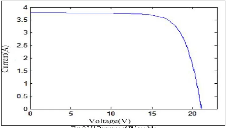
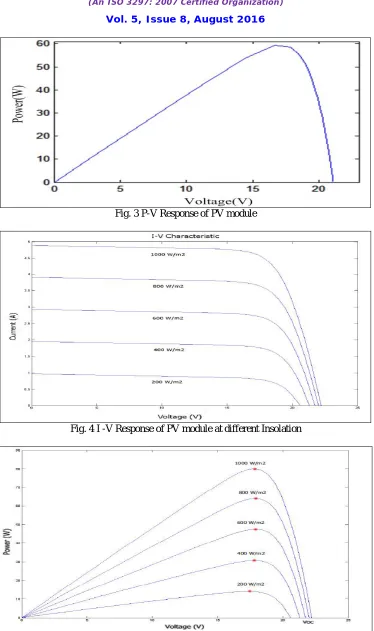
Fig. 3 P-V Response of PV module
Fig. 4 I -V Response of PV module at different Insolation
The P-V and I-V response of solar cell clear that to enhance the efficiency of PV system, it is required to operate system at MPP for specific current and voltage
.
III.MPPT TECHNIQUES
In order to always ensure the operating point on the maximum power point or close to it, specific circuit called MPPT is employed. Voltage and current are vary with temperature and insolation variation, so a MPPT is needed to track a single point i.e. MPP at which PV module operate with its maximum efficiency. This MPP is track by using a controller to a DC-DC converter which basically control the duty cycle of the converter. Solar system with MPPT technique is given below
-
Fig. 6 PV Module with MPPT Unit
There are various MPPT algorithm have been discussed in literature. Here a comparative study of P&O, IC and Fuzzy logic control technique is done, implementation through DC-AC converter is also done
.
A.
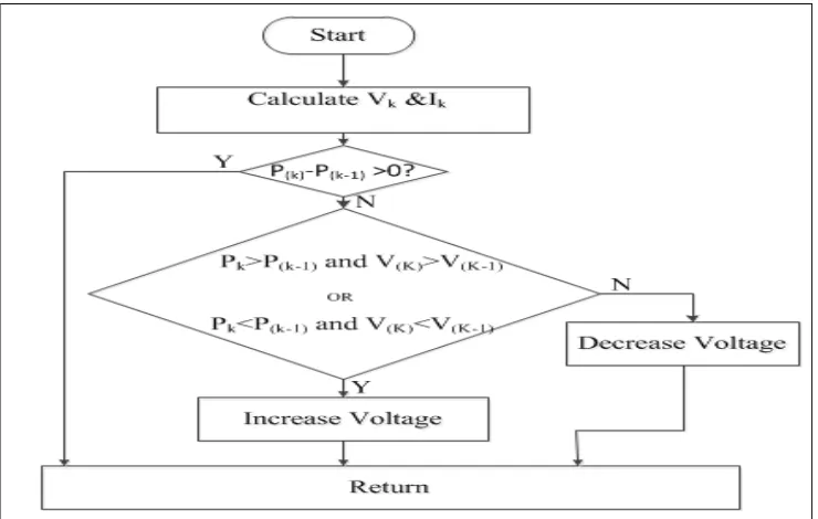
Perturb and observe (P&O)
It is simplest and most discussed MPPT technique to implement [12]. A perturbation is applied in the panel voltage and then power is tested. If the perturbation is in same direction of power than consider it otherwise change the direction. These steps are repeated until MPP is obtained. The flow chart of P&O is given below
-
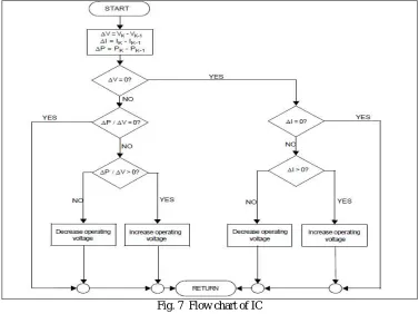
B. Incremental Conductance (IC)
The basic idea of this MPPT technique is depend on the slope of the derivative of power versus voltage which is zero, positive and negative at MPP, left of MPP and right of MPP respectively. In this technique the incremental conductance is compare with instant conductance [13]. On the basis of the result there is a decrement and increment in reference voltage until MPP is obtain while P&O is naturally oscillate around the MPP. The flow chart is given as-
Fig. 7 Flow chart of IC
C. Fuzzy logic control (FLC)
It is a new technique to obtain the peak power by controlling MPP in the system [14]. It consists of three parts:
a) Fuzzification
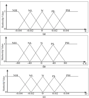
The real parameter are converted into the fuzzy variable [15]. In this proposed work two input variable are taken i.e. error (E) and change in error (CE). The expression for E and CE at instant K is given below.
1
1
PV PV
PV PV
P K P K
E K
I I K
(4)
1
CE K E K E K (5) The input E(K) demonstrates that at instant ‘K’ the working point is lies on left and right of the MPP and CE(K) shows the track of movement of this point.
(a)
(b)
(c)
Fig. 9 Membership function for (a) input E, (b) input CE, (c) output D b) Inference Engine
Table 1. Rule Base
CE
E
NH NL N PL PH
NH N N NH NH NH
NL N N NL NL NL
N NL N N N PL
PL PL PL PL N N
PH PH PH PH N N
Fig. 10 3-D diagram of rule base
c) Defuzzification
It is required to convert the fuzzy information obtain from inference engine into realistic term this process is known as defuzzification. It can be done by two method Centre of area (COA) and Max criterion method. Here COA method is used.
IV.SIMULATION MODEL
Fig. 11 Simulation diagram in MATLAB/SIMULINK
V.SIMULATION RESULTS AND ANALYSIS
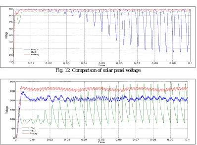
Fig. 12 Comparison of solar panel voltage
Fig. 14 Comparison of DC-DC converter current
Fig. 12,13,14 shows the comparative result of solar panel voltage , DC-DC output voltage , DC-DC output current when P & O, IC and Fuzzy logic controller is applied to control the duty cycle of DC-DC Converter. Fig. shows that Fuzzy logic controller gives more stable and less distorted results as compare to conventional techniques(P & O, IC). Fluctuations are less with FLC.
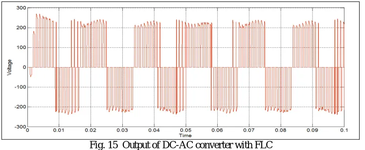
Fig. 15 Output of DC-AC converter with FLC
Fig. 15 shows the result of DC-AC converter when FLC based DC-DC converter output is given as input, this work as fundamental unit for intermittent system.
VI.CONCLUSION
A comparative study of three MPPT control unit (P&O, IC and Fuzzy logic) is presented in this paper. Comparison is done on the basis of panel voltage, output of DC-DC converter. Result shows that Fuzzy logic controller gives better response than conventional hill climbing techniques in terms of maximum power point traction. This FLC based MPPT system can be implemented to the grid with DC-AC converter Which can work as a fundamental unit for intermittent system.
REFERENCES
[1] P Olejarnik. “world energy outlook” Paris, France: International Energy Agency. 2010H. Simpson, Dumb Robots, 3rd ed; Springfield: UOS
Press, ,pp. 6-9, 2004.
[2] J Change, et al. “A review on the energy production, consumption, and prospect of renewable energy in china”. Renewable and Sustainable Reviews; 7:453-68, 2003.
[3] F Dincer. “The analysis on photovoltaic electricity generation status, poten- tial and policies of the leading countries in solar energy” Renewable & Sustainable Energy Reviews; 15:713-20, 2011.
[5] K.H Hussen..; I Muta,.; T Hoshino,.; M Osakada,. “Maximum photovolatic power tracking: An algorithm for rapidly changing atmospheric conditions,” IEE Gener. Transm. Distrib., 59-64, 1995 .
[6] Moacyr Aureliano Gomes de Bnto, Luigi Galotto, Jr., Leonardo Poltronieri Sampaio, Guilherme de Azevedo e Melo, and Carlos Aiberto Canesin, “Evaluation of the Main MPPT Techniques for Photovoltaic Applications,” IEEE Transactions On Industrial Electronics, Vol. 60, No. 3, M arch 2013.
[7] M. Young, D Hohm, M Ropp. “Comparative study of maximum power point tracking algorithms. Progress in photovoltaics,” Research and Applications; 11:47-62, 2003.
[8] A Zegaoui, M Aillerie, P Petit, JP Sawicki, A Jaafar, C Salame, JP Charles. “Comparison of two common maximum power point trackers by simulating of PV generators,” Energy Procedia,; 6:678-87, 2011.
[9] P Bhatnagar, RK Nema. “Maximum power point tracking control techniques: State-of-the-art in photovoltaic applications,” Renew Sust Energy Rev, ; 23:224-41, 2013.
[10] “Photovoltaic Modeling” Power Analytics Corporation 16870 West Bernardo Drive, Suite 330 San Diego, CA 92127, U.S.A.
[11] N.Pandiarajan and Ranganath Muthu, “Mathematical Modeling of Photovoltaic Module with Simulink,” International Conference on ElectricEnergy Systems (ICEES 2011), 3-5 Jan 2011.
[12] M.S.Sivagamasundari, P. Melba Mary and V.K. Velvizhi "Maximum Power Point Tracking For Photovoltaic System by Perturb and Observe Method Using Buck Boost Converter" International Journal of Advanced Research in Electrical, Electronics and Instrumentation Engineering Vol. 2,Issue 6, June 2013.
[13] A. Safari and S. Mekhilef, “Implementation of incremental conductance method with direct control,” in 2011 IEEERegion 10 Conference (IEEE Conference Publications, 2011), pp. 944–948.
[14] EH Mamdani, S Assilian. “An experiment in linguistic synthesis with a fuzzy logic controller,” Int. J Man-Machine Studies, ; 7(1):1-13, 1975. [15] AN Abd El-Shafy, FH Fahmy, EM Abou El-Zahab. “Maximum-power operation of a stand-alone PV system using fuzzy logic control,” Int