PHENOMENA OF PAIRED ECHOES AND
TRANSMISSION CHARACTERISTICS OF THE PULSE SIGNAL IN DISPERSIVE TRANSMISSION LINES WITH DISCONTINUITIES
Y. F. Gui and W. B. Dou State Key Lab of Millimeter Waves Southeast University
Nanjing 210096,P. R. China
Abstract—The performance of wideband radar system may be degraded by signal distortion occurring in anyplace of the transmission channel of the system. If the amplitude response is not flat or the signal delay is not constant in the transmission of the wideband signal,then signal distortion will occur,which can reduce the SNR and resolution. The available theory indicates that a small sinusoidal ripple variation in either amplitude-frequency or phase-frequency response of a linear system will cause signal distortion and the phenomena of paired echoes in the output signals of the time domain. In this paper,whether a dispersive transmission line with discontinuities will lead to the phenomena of paired echoes is discussed by means of finite difference time domain (FDTD) method and theoretical analysis. The results show that the technique of paired echoes is unsuited to analyze the influence of dispersive transmission line with discontinuities on time domain pulse signal. The method of Taylor series expansion shall be chosen as a more appropriate method. Meanwhile,simulations also show that a pulse signal transmitting in dispersive transmission lines with discontinuities including passive components such as filters and directional couplers will not lead to the phenomena of paired echoes.
1. INTRODUCTION
for propagation of time domain pulse signal,the influence due to dispersion and discontinuities of transmission line is investigated in this paper. Moreover,whether dispersion and discontinuities of transmission system will lead to the phenomena of paired echoes are also discussed. The effect of the amplitude and phase of signal deviating from the ideal is often studied by using the technique of paired echoes (not to be confused with target echoes). The technique was proposed by MacColl in 1931 [1] and developed further by Wheeler in 1939 [2]. It states that a small sinusoidal variation of either phase or amplitude with frequency in a linear system will produce a pair of echoes in waveform of the output signal,one lagging and the other leading the major response to the input signal.
Any actual system will produce some distortion. Signal distortion of radar is produced by amplitude and phase ripple associated with the radar’s transfer function. The total transfer function is the product of individual transfer functions of components in the signal transmission path,including transmitter,transmission line,antenna,propagation media,receiver components and signal procession. According to this technique,for a nonideal but linear system where the time domain pulse signal is inputted,if the amplitude and phase of the transfer function of the system can be described as a Fourier series expansion on the frequency band of interest and not all first order items of expression are zero,then the system will produce the phenomena of paired echoes. This phenomena were also analyzed in band-pass systems [3,4]. The technique of paired echoes has been successfully applied to the error analysis of amplitude and phase fluctuations of transfer function and extended to analysis of other nonideal models,in which the nonideal characteristics can be represented by convenient series of ideal model over the parameter range of interest [5]. When the input signal is linear FM signal,the distortion of characteristics in frequency domain or waveform in the time-domain in launching system will result in the phenomenon of paired echoes of impulse response [6,7].
phenomena of paired echoes exist when the time domain pulse signal is transmitted. Finally,we prove that the technique of paired echoes is unsuitable to analyze this system. The method of Taylor expansion should be chosen.
The second part discusses whether the discontinuities of transmission system will induce the phenomena of paired echoes. As we know,a single mismatch in source port or load port of a dispersive transmission line system will not introduce non-linear insertion phase shift. However,if two or more mismatches occur anywhere along the transmission line,a nonlinear phase variation with frequency will appear [8]. The variation of phase can be represented as a kind of ripple form. Whether the ripple form of the phase will produce the phenomena of paired echoes is the focus of our attention. In this paper,we explore the influence of discontinuities by simulating typical components such as filters,directional couplers.
2. THE TECHNIQUE OF PAIRED ECHOES AND ITS PARAMETERS ANALYSIS
A linear system can be described by its transfer function H(ω) or impulse responseh(t) as follows [9]:
so(t) = h(t)∗si(t) (1) So(ω) = H(ω)·Si(ω) (2) wheresi(t) is the input signal of the system,so(t) is the output signal, Si(ω) represents the spectrum of the input signal,So(ω) represents the spectrum of the output signal,the asterisk “∗” denotes convolution,ω is angular frequency,that is,
Si(ω) =
+∞
−∞ si(t)e
−jωtdt, S o(ω) =
+∞
−∞ so(t)e
−jωtdt and ω= 2πf.
The steady-state transfer function of a linear network is expressed in complex form as
H(ω) =A(ω)ejφ(ω) (3) whereA(ω), φ(ω)denote the amplitude and phase response of system respectively.
For a non-distortion linear system,the transfer function must satisfy
A(ω) = a0 (4a)
where the Eq. (4a) denotes that the amplitude-frequency response A(ω) is a constant independent of frequency; the Eq. (4b) denotes that the phase-frequency response φ(ω) increases linearly with frequency and produces the constant delay of output signal in time domain. It is well-known that a pulse signal is undistorted when it transmits through an ideal linear system,and only produces a time delay. However, in any actual linear system signal distortion including amplitude distortion and phase distortion is inevitable because there are always the fluctuations of the phase and amplitude.
MacColl had depicted a nonideal but linear system by perturbing the amplitude-frequency and phase-frequency of an ideal linear system and put forward the famous technique of paired echoes. The specific contents are described as follows.
Assume that transfer function of a system is
A(ω) = a0+ ∞
i=1
aicos(icω) (5a)
φ(ω) = b0ω+ ∞
i=1
bisin(icω) (5b)
where (5a) represents the cosine error modulation of amplitude response,(5b) represents the sinusoidal error modulation of phase response, ai and bi are constants, cis common modulation parameter of the two kinds of error modulations.
If only one term of the Fourier series (5a) and (5b) is considered, the model (5) is simplified to
A(ω) = a0+a1cos(cω) (6a)
φ(ω) = b0ω+b1sin(cω) (6b)
To obtain so(t) from si(t),we can get So(ω) by (2),then obtain so(t) by Fourier inverse transform withSo(ω),that is,
So(ω) = H(ω)·Si(ω) = (a0+a1coscω)ej(b0ω+b1sincω)Si(ω)
=
a0+a1
ejcω+e−jcω 2
ejb0ωS
i(ω)ejb1sincω
Bessel generating functions,that is,
cos[βsinωmt] = J0(β) + 2 ∞
n=1
J2n(β) cos[2nωmt] (7a)
sin[βsinωmt] = 2
∞
n=1
J2n−1(β) sin[(2n−1)ωmt] (7b)
After expandingSo(ω) by (7),by Fourier inverse transform we can obtain
so(t) =a0J0(b1)si(t+b0)
+J1(b1)
a0+
a1
b1
si(t+b0+c)−
a0−
a1
b1
si(t+b0−c)
+J2(b1)
a0+
2a1
b1
si(t+b0+2c)+
a0−
2a1
b1
si(t+b0−2c)
+J3(b1)
a0+
3a1
b1
si(t+b0+3c)−
a0−
3a1
b1
si(t+b0−3c)
+. . . . (8)
As the amplitude of error modulations, a1 and b1 are small.
When b1 1,by means of a small argument approximation of Bessel
function:
lim
x→0J0(x) = 1− x
2
2
; lim x→0
n=0
Jn(x) = (x/2)2
n! (9)
and we have
J0(b1)≈1, J1(b1)≈
b1
2, Jn(b1)≈0 (n≥2) (10) Substituting (10) into (8),(8) becomes
so(t) = a0J0(b1)si(t+b0)
+J1(b1)
a0+
a1
b1
si(t+b0+c)−
a0−
a1
b1
si(t+b0−c)
=a0
si(t+b0)+
1 2
b1+
a1
a0
si(t+b0+c)
+1 2
a1
a0−
b1
si(t+b0−c)
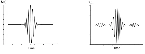
When c > 0 in (11), si(t+b0) is the “mainlobe” of the output
waveform, si(t+b0+c) is the “sidelobe” which leads the “mainlobe”
and si(t+b0−c) is the “sidelobe” which lags the “mainlobe”. Fig. 1
is the schematic diagram of the phenomena of paired echoes.
Time Si(t)
Time So(t)
(a) The waveform of input signal (b) The waveform of output signal
Figure 1. The schematic diagram of the phenomena of paired echoes. From (8) and (11),we know that
(1) when b1 is much less than 1,it is completely reasonable to
consider the first pair of sidelobe because the values of high-order Bessel function of b1 are very small;
(2) whena1 = 0 orb1 = 0,the phenomenon of paired echoes still
exist;
(3) whena1 = 0 andb1 = 0,there are only the main response and
not the phenomenon of paired echoes,which corresponds to the case of the ideal linear system.
3. THE DISCUSSION WHETHER DISPERSIVE TRANSMISSION LINE WILL LEAD TO THE PHENOMENA OF PAIRED ECHOES
3.1. FDTD Simulation of the Pulse Signal Transmitting in Dispersive Transmission Line
The FDTD method can give the evolution process of electromagnetic fields conveniently,and furthermore,display the physical processes clearly [10–12,23]. Therefore, the FDTD method is adopted to discuss whether dispersive transmission line will lead to the phenomena of paired echoes. The standard rectangular waveguide of W-band is taken as example.
1.27 mm respectively; the input signal is Gaussian pulse with the center frequency of 94 GHz; only the dominant modeH10is transmitted and
xaxis is the transmission direction; the step length of mesh ∆s=a/20; the time step ∆t = ∆s/2c. These settings are enough to ensure the stability of numerical calculation. The two ports of the waveguide are truncated by the PML absorbing boundary.
Simulating results is indicated in Fig. 2. Although the output waveform has changes in magnitude and phase shift compared with the input waveform,there is no the so-called phenomenon of paired echoes in hollow waveguide whose transmission length of is 16.5 mm. The electromagnetic wave is transmitted without reflection. The transmission coefficient S21 of the network is nearly equal to 1 and
the reflection coefficientS11 closes to zero.
0 500 1000 1500
-1.0 -0.5 0.0 0.5 1.0
Ez
The numbers of time step
0 500 1000 1500 2000
-1.0 -0.5 0.0 0.5 1.0
Ez
The numbers of time step
(a) The time domain waveform of input signal
(b) The time domain waveform of output signal
Figure 2. The waveform of input signal and output signal under dominant mode.
In order to enhance the dispersion of transmission line,we increase the length of the waveguide to 25.4 mm and adopt same excitation source as shown in Fig. 2(a); there is still no phenomenon of paired echoes on the output signal which is shown in Fig. 3. Furthermore,a waveguide filled withE-plane dielectric slab (εr= 6,tanδ = 1×10⁻³) as shown in Fig. 4 is also simulated when both material dispersion and mode dispersion are embodied,wherea= 2.54 mm,b= 1.27 mm,a1 =
0 400 800 1200 1600 2000 -1.0
-0.5 0.0 0.5 1.0
Ez
The numbers of time step
Figure 3. The output waveform of waveguide with increased length.
l
a b
a1
Figure 4. The structure of waveguide filled with E-plane dielectric slab.
0.0 0.1 0.2 0.3 0.4 0.5 0.6 -1.0
-0.5 0.0 0.5 1.0
Ez
Time (ns)
0.0 0.1 0.2 0.3 0.4 0.5 0.6 -1.0
-0.5 0.0 0.5 1.0
Ez
Time (ns)
(a) The waveform of input signal (b) The waveform of output signal
Figure 5. The waveform of two ports of waveguide filled withE-plane dielectric slab.
function,a theoretical analysis and interpretation are to be done as follows.
3.2.1.
Firstly,the technique of paired echoes can be extended to the following propositions:
Proposition A. If the transfer function satisfies the model (5), then as long as both ai and bi(i = 0) are not zeroes simultaneously there must be the phenomenon of paired echoes in output signal.
Proposition B.If the amplitude-frequency and phase-frequency of the transfer function satisfy the following model
A(ω) = a0+
n
i=0
aicos(icω) +ai sin(icω) (12a)
φ(ω) = b0ω+
n
i=0
bisin(icω) +bi cos(icω) (12b)
then as long as ai, bi, ai and bi are not all zero there must be the phenomenon of paired echoes in output signal.
3.2.2.
From the view of the propagation factor of guided wave,the transfer function of the lossless rectangular waveguide is
H(ω) =e−jkzz (13)
wherez is the displacement along the propagation direction,kz is the propagation constant;
kz =
k2−k2
c =
ω2ε
r
c2 −kc2 (14) k is the wave number in the media εr, kc is the intrinsic constant or cut-off wave number.
To conveniently compare model (12) and model (13),the two models are rewritten as follows:
H(ω) =
a0+
n
i=0
aicos(icω) +ai sin(icω)
ej
b0ω+
n
i=0[
bisin(icω)+bi cos(icω)]
60 65 70 75 80 85 90 95 100 105 110 0.0
0.2 0.4 0.6 0.8 1.0 1.2 1.4 1.6 1.8 2.0
Kz
(
*1
0
-3 )
Frequency (GHz)
Figure 6. Propagation constant curve of waveguide.
H(ω) =e−jφ1(ω) (15a)
where
φ1(ω) =kzz=
ω2ε
r c2 −k2c
z (15b)
What we concern is whether H(ω) of (15a) can be written into the form of H(ω) of (12c),that is,whether φ1(ω) can be expanded
into the Fourier series form as (12b). In fact,in the actual treatment φ1(ω) can not be expanded into the form of (12b). The reasons are
stated as follows:
A. Since φ1(ω) as shown in Fig. 6 is not the periodic function of
ω,the traditional Fourier series expansion can not be obtained. B. If a section of the definition ofφ1(ω) is intercepted and extended
periodically,then the resulted function can be expanded into the form of Fourier series. Although the series is convergent in terms of Dirichlet-Jordan test [14],but in reality there exist the following two problems: Firstly,the interception of the limited terms,which can approximate to the infinite terms of the series,will brings truncation error; secondly,because of the existence of discontinuous points due to the extension of the function,there must exist Gibbs phenomenon on convergence of the Fourier series [15],that is,as shown in Fig. 7 the amplitude of the neighborhood domain of discontinuous points have a greater oscillation when the superposition terms number of the series are different. Therefore,Ifφ1(ω) is expanded by the above approach,
Figure 7. The schematic diagram of the square wave approached by Fourier series.
error (including truncation error) unavoidably. The effect of paired echoes obtained by Proposition B is due to the approaching method of ripple oscillation essentially,rather than the real physical effects of φ1(ω). Theoretically,the more the terms number of the limited terms
intercepts,the weaker the effect of paired echoes resulting from the above treatment method is. However,no matter how small truncation error is,this expansion will always bring the effect of paired echoes, which the system itself does not lead to.
Therefore,model (13) can not be written into the form of model (12),that is,two models can not be uniformed. The transfer function of waveguide can not be analyzed by the generalized technique of paired echoes.
3.2.3.
In the common expansion method,Taylor series expansion is a different method from the approached method of ripple oscillation of Fourier series. So we attempt to expand φ1(ω) by means of Taylor series and
(13) is equivalent to the following expression.
H(ω) = A(ω)ejφ(ω) (16a)
φ(ω) = −
φ1(ω0)z+φ1(ω0)z(ω−ω0) +
φ1(ω0)
2! z(ω−ω0)
2+· · ·
+φ
(n) 1 (ω0)
n! z(ω−ω0)
2+· · ·
(16c)
We can easily know that as long as the appropriate expansion point ω0 is chosen,the series (16c) of φ(ω) must be convergent [12].
As for the transfer function model expanded by Taylor series,the following conclusion is correct.
Proposition C.If the amplitude-frequency and phase-frequency of the transfer function satisfy the following model
A(ω) = a0 (17a)
φ(ω) = b0+b1ω+b2ω2+· · ·+bnωn+· · · (17b)
then there is no phenomenon of paired echoes in the output signal so(t).
Therefore,when the model (16) is used to analyze the lossless rectangular waveguide,we can know there is no phenomenon of paired echoes in the output signal by using Proposition C. For other dispersive transmission lines,the same conclusion can be obtained because their transfer function models are similar to the case of rectangular waveguide.
4. THE INFLUENCE OF THE DISCONTINUITIES OF TRANSMISSION LINE ON TIME DOMAIN PULSE SIGNAL
In wideband radar system,the multiple reflections along the transmission lines,which can be caused by the inhomogeneity or discontinuity of transmission system,will produce the distortion of signals. Although the power of transmitted signal may be reduced by a single mismatch,wideband signals are not be distorted. However, when two or more mismatches or discontinuities occur anywhere along transmission line,the inter-reflection and superposition of the signal among discontinuities will produce a nonlinear phase variation with frequency. The nonlinear phase variation will lead to the distortion of signals,which is called the “long-line effect” of broadband systems in [8].
components with discontinuities on the time domain pulse signal is obtained.
Take waveguide as an example,several typical discontinuous structures are simulated.
4.1. Waveguide Loaded with Dielectric Block
As shown in Fig. 8(a) a rectangular hollow waveguide (a= 2.54 mm, b = 1.27 mm) is loaded with a dielectric (εr = 6) block,where d1 = d2 = d3 = 10 mm. The front surface and back surface of the
dielectric block constitute two discontinuity surfaces. The simulation results are shown in Figs. 8(b) and (c).
b
a
d1 d2
d3
0.0 0.1 0.2 0.3 0.4 -1.0
-0.8 -0.6 -0.4 -0.2 0.0 0.2 0.4 0.6 0.8 1.0
Ez
Time (ns)
(a) The rectangular waveguide loaded with a dielectric block
(b) The waveform of input signal
0.0 0.2 0.4 0.6 0.8 1.0 -0.8
-0.4 0.0 0.4 0.8
Ez
Time (ns)
65 70 75 80 85
-8 -7 -6 -5 -4 -3 -2 -1 0
|S
21
| /d
B
Frequency (GHz)
(c) The waveform of output signal (d) The curve of S21
Figure 8. The input waveform,output waveform andS parameter of a waveguide loaded with dielectric block.
When dielectric properties of loaded materials are changed into lossless medium (εr = 2) or loss medium (εr = 11.9 and tanδ = 4× 10⁻³) respectively,the figure of the output waveform and Sparameter curves are similar to Figs. 8(c) and (d).
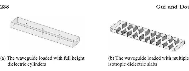
(a) The waveguide loaded with full height dielectric cylinders
(b) The waveguide loaded with multiple isotropic dielectric slabs
Figure 9. The schematic diagrams of some discontinuous structures.
peaks behind the main transmission peaks and no phenomenon of paired echoes. The same results can be obtained for the case of waveguide structure loaded with multiple dielectric blocks.
4.2. The Simulation of Other Discontinuous Structures By the simulation of the waveguide loaded with multiple dielectric cylinders and metal cylinders (see Fig. 9(a)),we know that there are several smaller transmission peaks behind the main transmission peaks and serious distortion of the main transmission peaks but no phenomenon of paired echoes.
By the simulation of the waveguide loaded with multiple isotropic dielectric slabs (see Fig. 9(b)),we know that this structure has certain filter characteristics. Compared with the input waveform,the output waveform has a very obvious multiple reflections,a serious distortion of the main transmission peaks,but no phenomenon of paired echoes. The conclusion in the case of filter structure which is consisted by microstrip line is similar,that is,the output waveform has obvious tailing phenomenon similar to Fig. 5(b),but no phenomenon of paired echoes. The results of simulation are not given here for saving space.
From the above simulation results,we can know that the discontinuities of transmission line (for example the waveguide and microstrip) do not produce the phenomenon of paired echoes when the time domain pulse signal is transmitting through them.
5. CONCLUSION
is appropriate to analyze it. The existence of dispersion and discontinuity in transmission system will lead to the distortion of time domain pulse signals,rather than the phenomenon of paired echoes. Meanwhile,microwave and millimeter-wave dispersion transmission line,transmission line including discontinuity and passive components such as filters,directional couplers will also not lead to the phenomenon of paired echoes.
REFERENCES
1. MacColl,L.,unpublished manuscript,cited by C. R. Burrows in “Discussion of paired-echo distortion analysis,” Proc. IRE
(Correspondence),Vol. 27,384,June 1939.
2. Wheeler,H. A.,“The interpretation of amplitude and phase distortion in terms of paired echoes,” Proc. IRE,Vol. 27,359– 384,June 1939.
3. Wheeler,H. A.,“The solution of unsymmetrical-sideband problems with the aid of the zero-frequency carrier,” Proc. IRE, Vol. 29,446–458,June 1941.
4. Bechtel,M. E.,“Generalized paired-echo analysis for bandpass systems,”Proceedings of IEEE,204–205,February 1969.
5. Robert,S. W.,“SAW diffraction analysis by paired echo superposition,” IEEE Trans. on Sonics and Ultrasonics,Vol. 23, No. 4,249–254,July 1976.
6. Cook,C. E.,“Pulse-compression paired-echo experiments,”
Proceedings of IEEE,383–384,February 1963.
7. Cook,C. E. and J. Paolillo,“A pulse compression predistortion function for efficient sidelobe reduction in a high-power radar,”
Proceedings of IEEE,377–385,April 1964.
8. Wehner,D. R.,High-Resolution Radar,Artech House,Boston London,1995.
9. Lynn,P. A.,An Introduction to the Analysis and Processing of
Signals,2nd edition,Macmillan,London,1982.
10. Taflove,A.,Advanced in computational Electodynamics: The
Finite-Difference Time-Domain Method,Artech House,Norwood,
Mass.,1998.
S-matrix computation of waveguide structures,” IEEE Trans
Microwave Theory Tech.,Vol. 41,2109–2115,1993.
13. Collin,R. E.,Field Theory of Guided Waves,Mc Graw-Hill Book Co.,New York,1960.
14. Chen,C. Z.,Mathematical Analysis,Vol. 2,High Education Press, Beijing,1983.
15. Zheng,J. L.,Signal and System,Vol. 1,Higher Education Press, Beijing,1981.
16. Collin,R. E.,Foundations for Microwave Engineering ,McGraw-Hill,Inc.,1992.
17. Hillion,P.,“Electromagnetic pulses in dispersive media,”Progress
In Electromagnetics Research,PIER 18,245–260,1998.
18. Hillion,P.,“Electromagnetic pulse propagation in dispersive media,” Progress In Electromagnetics Research,PIER 35,299– 314,2002.
19. Wu,H. C. and W. B. Dou,“A rigorous analysis and experimental researches of waveguide magic tee at W band,” Progress In
Electromagnetics Research,PIER 60,131–142,2006.
20. Wu,H. C. and W. B. Dou,“Field structures of waveguides junction circulators with irregular shaped ferrite simulated based on exact treatment,” Progress In Electromagnetics Research, PIER 57,33–54,2006.
21. Ho,M. and F. S. Lai,“Effects of medium conductivity on electromagnetic pulse propagation onto dielectric half space: One-dimensional simulation using characteristic-based method,”
Journal of Electromagnetic Waves and Application,Vol. 21,
No. 13,1773–1785,2007.
22. Lee,J. S. and D. P. Nyquist,“The proper EM field spectra of an open integrated microstrip waveguide,” Journal of
Electromagnetic Waves and Application,Vol. 18,No. 12,1605–
1620,2004.
23. Fayedeh,H.,C. Ghobadi,and J. Nourinia,“An improvement for FDTD analysis of thin-slot problems,”Progress In