DIFFRACTION EFFICIENCY ENHANCEMENT OF GUIDED OPTICAL WAVES BY MAGNETOSTATIC FORWARD VOLUME WAVES IN THE
YTTRIUM-IRON-GARNET WAVEGUIDE COATED WITH PERFECT MENTAL LAYERS
F. Wen and B.-J. Wu
Key Lab of Broadband Optical Fiber Transmission and Communication Networks of the Ministry of Education University of Electronic Science and Technology of China Chengdu 610054, P. R. China
Abstract—The diffraction efficiency (DE) of guided optical waves (GOWs) and the magneto-optic (MO) −3 dB bandwidth are key parameters in MO Bragg cells. To improve the diffraction performance, the MO Stokes interaction between magnetostatic forward volume waves (MSFVWs) and GOWs are studied by use of the coupled-mode theory in metal clad yttrium-iron-garnet (YIG) waveguides. Our analysis shows that, by adjusting the spacing of the metal layer from the ferrite surface, (1) the DE can be further increased by 7.32 dB compared with that of the inclined magnetization, but the MO bandwidth will be dropped down to the low level in the optimizing waveguide configuration; (2) when the DE and the MO bandwidth should be considered synthetically, a DE improvement of 3.9 dB with a bandwidth about 560 MHz is achieved corresponding to the large gain-bandwidth product. Thus, the YIG waveguide coated with perfect metal layers can be used to improve the performance of MO Bragg cells.
1. INTRODUCTION
by the appearance of metal layers. Our calculation indicates that, the GOW diffraction efficiency by magnetostatic forward volume waves (MSFVWs) is increased by the metal layer effects, especially in the case of the inclined bias magnetic field. At the same time, the MSFVW frequency resolution which is the key parameter in the MO spectrum analyzer is also improved to a certain extent by metal layer effects. Consequently, the performance of MO Bragg cells can be enhanced by a proper selection of the spacing between the YIG film and metal layers.
In the paper we focus on the MO Bragg interaction in obliquely magnetized yttrium-iron-garnet/gadolinium-gallium-garnet (YIG/GGG) waveguides coated with perfect metal layers. The dependences of the Bragg DE, the corresponding frequency and the
−3 dB bandwidth on the spacing of metal layers from the ferrite surface are investigated. And the maximum DE improvement of 7.32 dB is obtained when the spacing is equal to the thickness of the YIG film and the inclination angle θ is 15.5◦. However, the MO bandwidth is obviously dropped down when metal layers are close to the YIG film. To appraise the performance of a practical MO Bragg cell comprehensively, the gain-bandwidth product is applied to evaluate the metal effects on the Bragg DE and the MO bandwidth. A 3.9 dB improvement with a bandwidth about 560 MHz is achieved when the gain-bandwidth product is up to the maximum, which keeps 70% MO bandwidth of the case without metal layers.
2. THE MO COUPLED-MODE THEORY IN METAL CLAD YIG WAVEGUIDES
In the paper the metal/dielectric/yttrium-iron-garnet (YIG)/gadolinium-gallium-garnet(GGG)/metal (MDYGM) structure is considered. The dispersion relation and the dynamic magnetization of MSFVWs are derived by the method of surface magnetic permeability. And the MO coupled-mode equations of the inclined magnetization are solved when phase-matching conditions are satisfied, which can help to find the relation between the GOW power and the MSFVW dynamic magne-tization.
2.1. The Characteristics of MSFVW Propagation in the MDYGM Structure
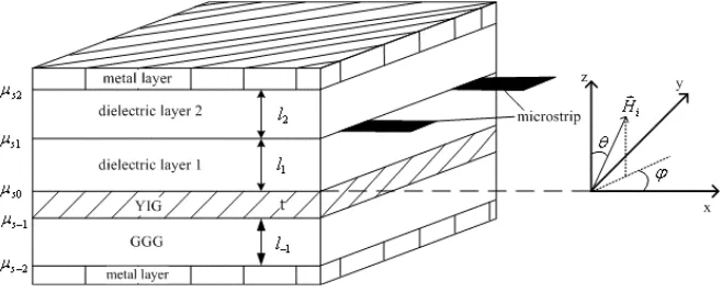
sandwiched between two perfect metal layers, as shown in Fig. 1. Hi is the effective internal direct current (dc) magnetic field, designated by (Hi, θ, ϕ).
Figure 1. The configuration of the metal clad YIG waveguide. Using the magnetostatic approximation [4] and the method of surface magnetic permeability defined byµs=−ihbz
y [5], the relations of
surface magnetic permeabilities (see also Fig. 1) are derived as follows:
µs1 = −sµ0−
µs2+sµ0tanh(sksl2)
sµ0−µs2tanh(sksl2)
(1a)
µs0 = −sµ0−
µs1+sµ0tanh(sksl1)
sµ0−µs1tanh(sksl1)
(1b)
µs0 =
upeα2t+vqeβ2t ks(peα2t+qeβ2t)
(1c)
µs−1 = sµ0
µs−2+sµ0tanh(sksl−1)
sµ0+µs−2tanh(sksl−1)
(1d) whereksis the MSW wavenumber,s=ks/|ks|,α2 =iks(µ23+µ32)+s
√
∆
2µ33 ,
β2 = iks
(µ23+µ32)−s √
∆
2µ33 , ∆ = (µ23+µ32)
2 −4µ
22µ33; p =µs−1ks−v,
q =u−µs−1ks,u =−iµ0µ32ks+µ0µ33α2, v=−iµ0µ32ks+µ0µ33β2;
and the relative permeability components µij (i, j = 1,2,3) are given in the Ref. [6].
The dispersion relation of MSFVWs can be obtained from the Equation (1c) : |ks| = tµ√33∆[mπ + 2 tan−1(a
b)], (m = 0,1,2· · ·), where a = sµ0
√
∆
2 (µs0 −µs−1), b = −µ 2 0[|
∆|
4 + (χacosϕsinθ) 2] −
µs0µs−1 −µ0χacosϕsinθ(µs0 +µs−1), µs0 = −sµ0tanh[sks(l1 +l2)],
According to m = ↔χ ·h, the effective complex envelope vector
gmof the MSFVW dynamic magnetization
min obliquely magnetized metal clad waveguide can also be given as follows:
gm=
˜
hy(0)
−iks(mt+ 1)
[mt(−iksχ12+χ13α2)A+ (−iksχ12+χ13β2)B]
˜
hy(0)
−iks(mt+ 1)
[mt(−iksχ22+χ23α2)A+ (−iksχ22+χ23β2)B]
˜
hy(0)
−iks(mt+ 1)
[mt(−iksχ32+χ33α2)A+ (−iksχ32+χ33β2)B]
(2) heremt= pqe(α2−β2)t;
˜
hy(l1) = iπF·(1)jks(·kµs1
s)
˜
hy(0) =
2sµ0˜hy(l1)
(sµ0−µs0)e−sksl1+(sµ0+µs0)esksl1
,jks =
J·sin(ksw
2 )
πksw is the Fourier transform of the uniform current distribution
on the microstrip line, F(1)(ks) = ∂(µsa−µsb)
∂k
k=ks
, in which µsa =
−sµ0−sµµs2+sµ0tanh(skl2)
0−µs2tanh(skl2) and µsb = sµ0
µs0+sµ0tanh(skl1)
sµ0+µs0tanh(skl1) are surface magnetic permeabilities above and below interfaces of the microstrip line, respectively;A= 4π2(1−e−α2t)
α2t(α22t2+4π2)
,B = 4π2(1−e−β2t) β2t(β22t2+4π2) .
2.2. The MO Bragg Interaction between GOWsand MSWs For simplicity, the effect of metal layers on GOWs is ignored, which can be reasonable when metal layers are lift off the YIG film sufficiently (typically more than 1µm) [8–10]. For the case, the conventional MO coupled-mode equations (CCME) [7] in the air/YIG/GGG (AYG) structure can be used to analyze approximately the MO diffraction effects in the metal clad waveguide.
the obliquely magnetized CCME [7]:
CT M(u)(LM O) =h1er1LM O +h2e−r1LM O+h3er2LM O+h4e−r2LM O
CT M(d) (LM O) =r
2 1−m1
m2
h1er1LM O+h2e−r1LM O
+r
2 2−m1
m2
h3er2LM O+h4e−r2LM O
CT E(u)(LM O) =−m8r1
m5
h1er1LM O−h2e−r1LM O
−m9r2
m5
h3er2LM O−h4e−r2LM O
CT E(d)(LM O) =m6r1
m5
h1er1LM O−h2e−r1LM O
+m7r2
m5
h3er2LM O−h4e−r2LM O
(3) and then the Bragg DE can be calculated by
η=
CT M(d)(LM O)
2
+
CT E(d)(LM O)
2
(4)
because the four kinds of the frequency-unshifted and -shifted of the
T M and T E light are coupled each other in the obliquely magnetized waveguide. The parameters shown in Equations (3) and (4) are given as follows: CT M(.) (x) and CT E(.)(x) designate the complex amplitudes of transverse electric field components of the TM and TE modes, the superscripts (u) and (d) designate the frequency-unshifted and -shifted light;LM O is the MO interaction length; and
m1=κDCzy κ DC yz +κ
AC zy 1 2 gm κACyz
1 2
g∗m
,
m2 =κDCzy κ AC yz 1 2 gm
+κDCyz κACzy 1 2 gm
m3 =κACzy
1 2 g∗ m
κDCyz +κDCzy κACyz 1 2 g∗ m ,
m4 =κACzy
1 2
g∗m
κACyz 1 2 gm
+κDCzy κDCyz , m5=κACzy
1 2 g∗ m κACyz
1 2 gm
−κDCzy 2
,
m6=κACzy
1 2 g∗ m −κ DC zy m2
r21−m1
m7=κACzy
1 2
g∗
m
−κ
DC zy
m2
r22−m1
,
m8 =κDCzy −
κACzy
1 2
gm
m2
r21−m1
,
m9 =κDCzy −
κACzy
1 2
gm
m2
r22−m1
;
r1=
(m1+m4) +
√
∆m 2 , r2 =
(m1+m4)−
√
∆m
2 ,
∆m= (m1−m4)2+4m2m3;κACij (
1 2
gm),κACij (12g∗m) andκDCij (i, j =y, z) are defined as the Ref. [7],gm can be obtained form the Equation (2); for the TM incident light,h1 =h2 =
m1−r22
2(r21−r22) and h3 =h4 =
r2 1−m1
2(r12−r22);
and for the TE incident light, h1 = −h2 = 2r m5m7
1(m6m9−m7m8) and h3 =−h4 = 2r −m5m6
2(m6m9−m7m8).
3. CALCULATION AND DISCUSSION
For the practical MO waveguides used generally in Bragg diffraction experiments, the thickness of the GGG substrate is several hundred times larger than that of the ferrite and the microstrip line transducers are directly deposited on the YIG film for the high excitation efficiency. In this case, the waveguide structure mentioned above is reduced into the metal/dielectric/YIG/GGG (MDYG) four-layered waveguide with
l1 = 0 and l−1 → ∞, which will be considered in the following.
To compare with the experiment data and theoretical analyses, the parameters are taken from the experiment by Young and Tsai [11]: the wavelength of incident TM0 light is 1.317µm; the thickness of YIG is
9µm, the width and length of microstrip line conductor are 24µm and 8.8 mm, respectively; the dc applied magnetic field H0 is 279 kA/m,
the anisotropic field is 16 kA/m, and the saturation magnetization
M0 is 139 kA/m; the refractive indices of YIG and GGG are 2.2 and
1.59, respectively; the MO coefficients are f1 = 2.44×10⁻⁹(A/m)1,
f44= 5.84×10⁻¹⁵(A/m)2, ∆f =−2.92×10⁻¹⁵(A/m)2.
In what follows, the MO interaction in metal clad YIG waveguides is discussed; and then the dependences of the Bragg DE and the
3.1. Metal Layer Effectson the MO Bragg Interaction
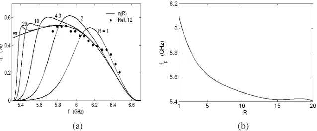
The Bragg DEη calculated by the Equation (4) is shown in Fig. 2(a), in which the relative dielectric thicknessR is defined byR=l2/t. The
experiment data [11] consist with our theoretical results at R = ∞ in the normal magnetization (θ = ϕ= 0◦). It is clear from Fig. 2(a) that: (1) the presence of the metal layer decreases the DEs at lower frequency end and then the MO −3 dB bandwidth B−3 dB; (2) by
properly adjusting the relative dielectric thickness R, the Bragg DEs can be improved comparison with the case of the conventional AYG waveguide; (3) and the frequencyfP corresponding to the peak Bragg DEηp can be tunable by the spacing of the metal layer from the YIG film. The dependence of the frequency fP on the relative dielectric thickness R is shown in Fig. 2(b). The range of the frequency fP almost covers the whole MO −3 dB bandwidth of the case without metal layers, which means that the DE improvement can be obtained in the frequency range of interest.
(a) (b)
Figure 2. (a) The Bragg DEs in different waveguide configurations, (b) the dependence of the frequency fP on the relative dielectric thicknessR.
3.2. The DE Improvement by Metal Layer Effects
The MSFVW frequency range is the function of the inclination angleθ
[12]. To compare with the results above, the MSFVW frequency range at 5.46 ∼7.52 GHz will be discussed corresponding to the inclination angle θ at 0◦ ∼ 21.7◦. In our calculation, the direction of the bias magnetic field is changed while the magnitude keeps fixed. And the inclination angle ϕis equal to 180◦, because the maximal DE can be achieved in the x-z plane for the case of the noncollinear interaction of GOWs and MSFVWs [12].
For a given inclination angleθ, the relative dielectric thickness R
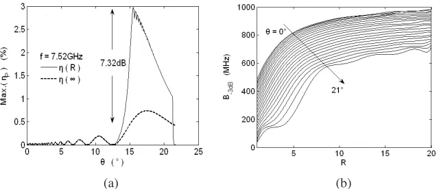
is changed for the DE improvement at one MSFVW frequency. The maximum DE improvement is obtained at f = 7.52 GHz, and the dependence of the maximum DE on the inclination angle θ is given in Fig. 3(a). A 7.32 dB improvement is achieved at θ = 15.5◦ and
R = 1. However, the MO −3 dB bandwidth will be decreased as the magnetization direction deviates from thezaxis and the metal layer are close to the YIG film, and the results are shown in Fig. 3(b). When the maximum DE improvement is obtained, the MO bandwidth is dropped down to 140 MHz. Thereby a more comprehensive evaluation should be given for a MO Bragg cell.
(a) (b)
Figure 3. (a) The dependence of the maximum DE on the inclination angle θ, (b) the MO −3 dB bandwidth B−3 dB in different obliquely
magnetized waveguides.
The gain-bandwidth product defined by Gη × B−3 dB = 10 ×
lg( ηP(R)
M ax(η(∞)))×B−3 dB(dB·MHz) at a given magnetization direction is
Figure 4. The dependence of the gain-bandwidth product on the relative dielectric thicknessR and the inclination angle θ.
θ is shown in Fig. 4. When the gain-bandwidth product is up to the maximum, the DE improvement Gη(R= 8.4)|θ=21◦ is equal to 3.9 dB
and the−3 dB bandwidth is 560 MHz. Almost 70% MO bandwidth is kept comparing with the case without metal layers, and the maximum DE improvement of 3.9 dB is also obtained.
4. CONCLUSION
The MSFVW dispersion relation and the dynamic magnetization in the obliquely magnetized metal clad YIG waveguide are obtained by the method of the surface magnetic permeability, and the noncollinear Stokes interaction between the GOWs and the MSFVWs is discussed according to analytic expressions of the MO coupled-mode equations. By analyzing the diffraction process of the GOWs with the MSFVWs in the MDYG waveguide, it is known that: (1) the MO diffraction efficiency can be improved by a proper selection of the spacing between the YIG film and metal layer, and the maximum DE improvement of 7.32 dB can be obtained; (2) the gain-bandwidth product can be used to evaluate the metal effects on the Bragg DE and the MO bandwidth synthetically, and the 3.9 dB improvement and 560 MHz bandwidth are achieved when the product is up to the maximum.
ACKNOWLEDGMENT
REFERENCES
1. Daniel, M. R., J. D. Adam, and T. W. O’Keeffe, “Linearly dis-persive delay lines at microwave frequencies using magnetostatic waves,”IEEE Ultrasonics Symposium Proc., 806–809, 1979. 2. Adam, J. D., T. W. O’Keefe, and M. R. Daniel, “Magnetostatic
wave devices for microwave signal processing,” SPIE Real-Time Signal Proc., Vol. 241, 96–103, 1980.
3. Sethares, J. C., J. M. Owens, and C. V. Smith., “M.S.W. nondis-persive electronically tunable time delay elements,” Electron. Lett., Vol. 16, 825–826, 1980.
4. Ganguly, A. K. and D. C. Webb, “Microstrip excitation of magnetostatic surface waves: theory and experiment,” IEEE Trans. Microwave Theory Tech., Vol. 23, 998–1006, 1975.
5. Emtage, P. R., “Interaction of magnetostatic waves with a current,”J. Appl. Phys., Vol. 49, 4475–4484, 1978.
6. Wu, B.-J., “Analysis of mode characteristics of microwave magnetostatic waves,”Journal of Microwares, Vol. 22, 5–7, 2006. 7. Wu, B.-J. and K. Qiu, “An effective method for improving diffraction performance of magnetostatic backward volume wave based magneto-optic Bragg cells by using an appropriately titled bias magnetic field in YIG film plane,” J. Magn. Magn. Mater., Vol. 303, 227–231, 2006.
8. Ma, C. and J. Cao, “TM mode optical characteristics of five-layer MOS optical waveguides,”Opt. Quant. Eletron., Vol. 26, 877–884, 1994.
9. She, S. X., “Accurate perturbation analysis of metal-clad and absorptive multilayer dielectric waveguides in near cutoff,” Opt. Commun., Vol. 135, 241–246, 1997.
10. Kumar, D., V. K. Sharma, and K. N. Tripathi, “Frequency response of metal clad planar optical waveguides,” Optics Laser Technol., Vol. 39, 68–71, 2007.
11. Young, D. and C. S. Tsai, “GHz bandwidth magneto-optic interaction in yttrium iron garnet-gadolinium gallium garnet waveguide using magnetostatic forward volume waves,” Appl. Phys. Lett., Vol. 53, 1696–1698, 1988.