Performance Improvement of Patch Antenna Using Circular Split
Ring Resonators and Thin Wires Employing Metamaterials Lens
Adel A. A. Abdelrehim and Hooshang Ghafouri-Shiraz*
Abstract—In this paper, the left-handed metamaterial which acts as a lens is employed to improve the performance of a microstrip patch antenna. The left-handed metamaterial used in this work is a three-dimensional periodic structure which consists of circular split ring resonators and thin wires. The three-dimensional periodic metamaterial structure shows angular independency characteristics in wide range angles, so it acts as a metamaterial lens. However, the MTM structure infinite periodicity truncation has no impacts on the MTM lens scattering, effective parameters and homogeneity. The left-handed metamaterial is placed in front of the microstrip patch antenna and due to the negative refractive index property of the left-handed metamaterial; the radiated electromagnetic beam size decreases which results in a highly focused beam. The proposed antenna has been designed and simulated using CST microwave studio, and the metamaterial effective parameters are extracted from the S parameters by using Nicolson-Ross-Weir algorithm and by selecting the appropriate ambiguity branch parameter. Furthermore, the angular independency of the metamaterial lens has been verified by rotating the metamaterial structure with respect to the excitation probe of the transverse electromagnetic waves and extracting the S-parameters and the effective parameters for each rotation angle. A parametric analysis has been performed to study the effects of the patch antenna and left-handed metamaterial lens separation and the size of the three-dimensional left-handed metamaterial structure on the radiating properties and the impedance matching of the proposed antenna. For the experimental verification, the proposed antenna operating at 10 GHz is fabricated; the return loss, radiation pattern and gain for the proposed antenna with and without metamaterial are measured. Furthermore, the results show that the antenna gain is improved by 4.6 dB which validates the concept of beam focusing using negative refractive index metamaterial structure, while the return loss and bandwidth are slightly reduced. The simulation and experiment investigated the idea of the beam focusing using negative refractive index metamaterial lens in microwave regime.
1. INTRODUCTION
Microstrip patch antennas offer an attractive solution to compact, conformal and low-cost designs of many wireless application systems [1]. It is well known that the gain of a single patch antenna is generally low, and it can be increased by using array of patches or by reducing the surface wave, which can create ripples in the radiation pattern and hence reduce the main loop gain. Several methods have been proposed to reduce the effects of surface waves [2–8]. One approach suggested earlier is the synthesized substrate that lowers the effective dielectric constant of the substrate either under or around the patch [2, 3]. Other approaches use parasitic elements [4, 5] or a reduced surface-wave antenna [6–8]. During the last decade, a metamaterial layer with negative refractive index has been developed to act as a lens [9]. This metamaterial (MTM) lens can be placed in front of a patch
Received 11 May 2016, Accepted 9 September 2016, Scheduled 26 September 2016
* Corresponding author: Hooshang Ghafouri-Shiraz ([email protected]).
antenna, and due to the negative refractive index property of the MTM, the radiated electromagnetic beam size decreases which results in a highly focused beam, hence the gain, directivity and radiation efficiency can be significantly improved [10, 11]. Metamaterials are artificial materials which exhibit non-natural properties such as negative permittivity, negative permeability and negative refractive index (NRI) from physical dimensions and geometrical shapes rather than chemical composition [12– 17]. Metamaterials which have simultaneous negative permittivity and negative permeability are called left-handed materials (LH-MTM), in which the electric field E, magnetic field H, and wave vector k
form a left-handed system.
Recently, several structures have been proposed which exhibit the LH-MTM properties such as omega shape, spiral multi-split, fishnet, and S-shape [18–20]. After that, many researchers have been interested in investigating this artificial material, and several of them used the LH-MTM to improve the properties of the microwave devices such as antennas and filters [21]. Many papers have been published regarding the LH-MTM integrated with antennas, and their properties have been analyzed [22–24]. Although other metamaterials such as frequency selective surface (FSS) and electromagnetic band gap (EBG) have been used to enhance the gain of an antenna [25, 26], the NRI property of the LH-MTM was exploited to improve the directivity and gain of the antennas [27–29]. In addition, a metamaterial structure composed of wire medium was given by Burghignoli et al. for directive leaky-wave radiation from a dipole source [30]. It was shown that the electromagnetic waves in the media can be congregated in a narrow rectangle area properly when applied to a monopole antenna; this structure can greatly improve the directivity of the antenna. Also, metamaterials have been designed and investigated in the THz frequency range for developing new THz devices such as antennas, filters, sensors, and absorbers [31–34]. Furthermore, metamaterial structures composed of 3-D metal grid superstrate have been used to improve the directivity of the antenna [35, 36]. It should be noted that the aperture size of the metamaterial superstrate is much more than the size of the patch which makes the antenna very bulky. Also, zero index medium metamaterial superstrate is used to develop a high gain and wideband antenna [37]. It is clear from the structure of the antenna that the metamaterial superstrate uses via to resemble shunt inductance, which makes it difficult in fabrication. Photonic crystal-based resonant antenna presented in [38] is a high directive antenna, but it is very bulky and has a narrow bandwidth. Al`u et al. proved numerically and theoretically that a PEC screen with a small hole covered by two subwavelength metamaterial structures (i.e the PEC screen with a small gap is covered by metamaterial structures from both sides) is used to increase the wave transmission through this aperture, and hence the directivity of the antenna can be improved [39]. Planar metamaterial with NRI has been developed using split ring resonator (SRR) in [40]. In this work, a planar double-sided structure composed of CSRR s/TWs with NRI is used as a cover for the patch antenna to improve antenna directivity. The novelty of using such a structure to improve the antenna gain is that it is easy in fabrication and has a small size compared to the published work in [35–38]. However, the CSRR/TWs have strong electric and magnetic couplings compared with SRR (of [40]) due to the double-sided structure. As a result, the patch antenna incorporated with NRI cover composed of CSRRs/TWs may have a higher gain than that covered by SRR only.
2. ANALYSIS AND DESIGN OF THE PROPOSED ANTENNA
In order to investigate the idea of beam focusing using NRI MTM Lens, a microstrip patch antenna operating at 10 GHz and a CSRR/TW LH-MTM unit cell resonating at the same frequency as that of the patch antenna are designed and simulated using CST microwave studio. The conventional patch antenna has a length L and width W of 8.6 mm and 11.86 mm, respectively, and is printed on an RT/Duroid 5880 substrate with a relative permittivity of εr = 2.2 and thickness ofh = 1.57 mm. The patch is fed by a 50 Ω microstrip line and is matched with quarter wavelength transformer which has a line length LT and width WT of 7 mm and 0.3 mm, respectively. The quarter wavelength transformer length and/or the patch width were optimized to give a good impedance matching. The size of the substratea×bwas calculated from the formula (W + 6h)×(L+ 6h) [42]. The conventional microstrip patch antenna (MSA) parameters such as gain, bandwidth, and directivity and radiation efficiency are calculated theoretically using cavity model [43]. The Directivity (D) is calculated as follows
D =
2
4b2π2 I1λ0
1 +g12
(1)
I1 = π
0
sin2
k0bcos (θ)
2
tan2(θ) sin (θ)dθ (2)
g21 = 1
120π2 π
0
sin2
πbcos (θ)
λ0
tan2θsinθJ0
2πa λ0 sinθ
G dθ (3)
where Jo(x) is the zeroth-order Bessel function, ko the free space wave number equals λ0/2π, a the
substrate length equals W + 6h, b the substrate width equals W + 6h, G the radiation inductance
G= 1/Rr, and Rr the radiation resistance and given by [43]
Rr = 120π
2
I1
(4)
The bandwidth BW of the MSA can also inversely proportional to its total quality factor QT and
is given by [38]
BW = VSWR−1
QT
√
VSWR (5)
The total quality factorQT is given by [37]
1
QT =
1
Qr +
1
Qc +
1
Qsw +
1
Qd (6)
where Qr, Qc, Qsw and Qd are the radiation, conductor, surface wave and dielectric quality factors, respectively. The relationship between VSWR and return loss S11 is as follows [44].
S11 (dB) = 20 log10
VSWR VSWR−1
(7)
The MSA radiation efficiency is given by [43]
e= QT
Qr
= QdQcQsw
QswQcQd+QswQcQr+QswQrQd+QrQdQc
(8)
The gain Gof the MSA is given by [43]
G=eD (9)
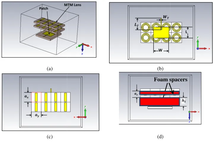
However, the 3-D CSRR/TW LH-MTM structure is designed with specific periodicities ofax, ay, and az in x, y, and z, respectively, which satisfies the homogeneity condition of the LH-MTM as shown in Figs. 1(b) and 1(c). Different layers of the MTM structure are attached to the conventional patch antenna by using foam spacer, since it has effective parameters closed to the air, so it will have no impacts on the antenna performance. The detailed dimensions, the frequency response and angular response of the CSRR/TW MTM unit cell constructing the MTM lens will be given in Subsections 2.1, and 2.2. After that, the proposed antenna is simulated in CST for different sizes of the 3-D CSRR/TW structure employing the MTM lens at different separations hS between the patch and the MTM lens; as a result, the optimized structure of the proposed antenna can be obtained.
(a)
(c)
(b)
(d)
Foam sspacers
Figure 1. The structure of the proposed antenna, (a) 3-D view, with hidden foam spacer located between the patch and the MTM lens and between the different layers of the MTM lens, (b) bottom view, (c) top view and (d) side view with viewed foam spacer.
2.1. Frequency Response of CSRR/TW MTM Unit Cell Resonating at 10 GHz
Here, a unit cell of CSRR/TW is designed and simulated in CST in which when repeated in two dimensions, it may give us a negative effective permittivity (ε), negative effective permeability (μ) and hence a negative refractive index (n) around the interesting frequency of 10 GHz [21, 35]. The dimensions of the 2-D CSRR/TW MTM structure are optimized in order to give a simultaneous negative permittivity and negative permeability in a frequency range to be matched with the bandwidth of the patch antenna designed in the last subsection, to achieve an optimal beam focusing when it is integrated with the patch antenna. The CSRR is a copper layer with thickness t of 35µm mounted on the top side of a RT/Duriod 5880 dielectric substrate with relative dielectric permittivity εr of 2.2 and height h = 1.57 mm, and the TW is mounted on the other side, i.e., the MTM structure is a double-sided process structure. The CSRR/TW unit cell depicted in Fig. 2 was designed using the CST Microwave Studio to resonate at 10 GHz. The CSRR/TW parameters are: a= 4.5 mm, g= 0.3 mm, r1i = 1 mm,
r1o= 1.4 mm,r2i = 1.8 mm,r2o= 2.1 mm,LT W = 4.2 mm. WT W = 1 mm and t= 17µm.
(a)
(c)
(b)
(d)
Figure 2. The MTM structure composed of CSRR/TW MTM unit cell with infinite periodicity in x
andy directions, (a) front view, (b) back view, (c) and (d) indicate 3-D view with boundary conditions of unit cells in x andy directions and the feeding source in thex-y plane.
walls at the back and front sides since the magnetic field is polarized in thex-direction and also electric walls on the left and right sides as the electric field is polarized in the y-direction. The theoretical resonant frequency of the CSRR/TW unit cell is 10 GHz, according to the theories developed in [21, 35], which is matched with the operating frequency of the patch antenna. The transversal periodicity is
a = 4.5 mm, less than 1/8 of the free space wave length at resonance, which is used to construct the 3-D MTM periodic structure to employ the MTM lens as will be illustrated in the next subsection.
Then, the effective parameters of MTM unit cell with infinite periodicity in x and y directions, including effective permittivityε, effective permeabilityμ, and refractive index n, have been extracted from the S-parameters using Nicolson-Ross-Weir (NRW) approach [45–49], and the results are plotted as shown in Figs 3(b), (c) and (d), respectively for two different branch ambiguity factors p of 0 and 1 values. According to the theory developed in [46], the correct branch ambiguity factor for this MTM structure is p= 0 since it is a thin MTM slab. Figs. 3(b), (c) and (d) illustrate that the real parts of the effective permittivity ε, effective permeabilityμ and effective refractive index n, respectively, are negative around the resonance frequency of 10 GHz atp= 0. In [40], the authors proved that the MTM effective parameters extraction based on theS-parameters method has no ambiguity related to the sign of the wavenumberksand the intrinsic impedanceηsof the metamaterials layer, while it has ambiguities related to the branch of the complex logarithm. Based on this method, the effective permittivityεsand effective permeabilityμs are given as follows:
εs = ks
ωηs (10)
ε = ε+jε= εs
ε0 (11)
where ε and ε are the real and imaginary parts of the relative (effective) permittivity of the MTM slab, respectively, and εis the MTM slab relative permeability,ε0 the free space permittivity.
μs = ksηs
(c) (d)
(e)
(a) (b)
Figure 3. The CSRR/TWs infinite 2-D periodicity MTM structure with negative effective parameters around the fundamental resonance frequency of 10 GHz, extracted at unambiguity branch parameter
p = 0 [46], (a) S-parameters magnitude, (b) S-parameters phase, (c) effective permittivity (ε), (d) effective permeability (μ) and (e) refractive index (n).
μ = μ+jμ= μs
μ0 (13)
where μ and μ are the real and imaginary parts of the relative (effective) permeability of the MTM slab, respectively, and μis the MTM slab relative permeability, μ0 the free space permeability.
The intrinsic impedance in the MTM layer ηs can be calculated from the free space intrinsic
impedanceη0 which is 120πΩ and the MTM S-parameters as follows:
ηs=±η0
(S11+ 1)2−S212
(S11−1)2−S212 (14)
The wavenumber ks inside the MTM layer of thicknessdcan be expressed as follows, where
ks = j
dlog (Z) =
1
d(−(Arg(Z) + 2πp) +jlog(Z)) (15)
Z = S21(ηs+η0) (ηs+η0)−S11(ηs−η0)
(16)
case, the MTM slab is thin, since the relation between the wavelength λs of 30 mm at the predefined
interesting frequency which is 10 GHz and the thicknessdof the MTM slab which is 1.6 mm isλs>2d. As a result, |ks|d < π and therefore, Arg(Z) is limited to the interval [−π, π], so p is set to 0 in Equation (13). Thus, the material parameters can be extracted unambiguously for electrically thin slab which is the case of this paper.
Figures 3(a) and 3(b) show that the CSRR/TWs MTM unit cell with infinite 2-D periodicity resonates at a fundamental frequency of 10 GHz and has a negative effective parameters around 10 GHz as shown in Figs. 3(c), 3(d) and 3(e). However, the bandwidths of the negative effective parameters of the CSRR/TWs MTM unit cell with infinite 2-D periodicity can be widened if the unit cell dimensions are increased, and the first harmonic resonance of the CSRR/TWs unit cell is chosen instead of the fundamental resonator. To do so, the dimensions of the CSRR/TWs MTM unit cell shown in Fig. 2 are redesigned to have a first harmonic resonance around 10 GHz with a wider bandwidth. The CSRR/TWs MTM unit cell parameters are: a = 8 mm, g = 0.3 mm, r1i = 2 mm, r1o = 2.5 mm,
r2i = 3 mm, r2o = 3.5 mm, LT W = 7 mm, WT W = 1 mm and t = 17µm. The effective parameters
of the CSRRs/TWs unit cell with infinite 2-D periodicity, including effective permittivity ε, effective permeability μ, and refractive index n, have been extracted from the S-parameters using the method presented in [46] for unambiguity branch parameterpof 0. Figs. 4(a) and 4(b) show that the infinite 2-D periodicity CSRR/TWs unit cell has bandpass frequency response with a center frequency of 10 GHz. However, the real part of the effective permittivity, effective permeability, and refractive index are
(e)
(a) (b)
(c) (d)
Figure 4. The 2-D infinite periodicity CSRR/TWs MTM structure with negative effective parameters around the first harmonic resonance frequency of 10 GHz, extracted at unambiguity branch parameter
negative around 10 GHz as shown in Figs. 4(c), 4(d) and 4(e), respectively. Furthermore, according to the theory developed in [46], the selected ambiguity branch parameter is p= 0 since the structure is a thin MTM slab. It is important to notice that as the ambiguity branch parameter is chosen properly, the non-Lorentzian response is minimized. By comparing the scattering parameters shown in Figs. 3(a) and (b) with the effective parameters shown in Figs. 3(c) to (e), it is clear that far away from resonance, the effective parameters have DC offset values, and they have negative real effective parameters after resonance. However, the MTM structure exhibits simultaneous negative effective parameters.
2.2. Angular Response, Infinite Periodicity Truncation Impacts and Lens Verifications of the CSRR/TWs NRI MTM Structure
In this section, the angular response of the CSRR/TWs structure with 2-D infinite periodicity is studied to verify the angular independency of the CSRR/TWs NRI MTM structure to ensure that the MTM structure designed in the previous section has a negative refractive index (NRI) and good reflection and transmission characteristics in a wide band of angles, and hence the MTM structure can be used to act as a lens to focus the EM waves [9]. As a result, the radiation parameters of the patch antenna such as gain, directivity and radiation efficiency will be improved, if the MTM structure is placed in the front of the patch antenna. Also, the infinite periodicity truncation impacts of the MTM structure on the effective parameters of the MTM structure are studied.
Firstly, to verify the angular independency characteristics of the CSRR/TWs MTM structure, the MTM structure is rotated from 0 degree to 180 degrees with respect to the excitation probe of the Transverse Electromagnetic Waves (TEM) waves. Due to the symmetry of the MTM structure, it will reach its initial orientation angle of 0 degree if it is rotated by 180 degrees, so no need to rotate the structure by 360 degrees to check the angular independency of its characteristics. For each orientation angle of the MTM structure from 0 to 180 degrees, the transmission, reflection and effective parameters are traced, and then they are compared for all the rotation angles. If the MTM structure has good transmission and reflection characteristics as well as simultaneous negative effective permittivity, negative effective permeability and NRI for all rotation angles from 0 to 180 degrees, then it can be said that the structure has angular independency and can act as a MTM lens. This task has been achieved by fixing the direction of the excitation TEM wave and rotating the CSRR/TWs MTM structure
(c) (d)
(a) (b)
(a) (b)
(c) (d)
(d) (e)
Figure 6. The 2-D infinite periodicity CSRR/TWs MTM structure with negative effective parameters around the first harmonic resonance frequency of 10 GHz, extracted with ambiguity branch parameterp
of 0 [46] and at different rotational angles of 0, 45, and 180 degrees with respect to the excitation TEM wave direction, (a) real part of effective permittivity (ε), (b) imaginary part of effective permittivity (ε), (c) real part of effective permeability (μ), (d) imaginary part of effective permeability (μ), (e) real part of refractive index (n), and (f) imaginary part of refractive index (n).
with respect to the source. Then, for selected rotational angles of 0, 45, and 180 degrees, the scattering parameters of the structure are traced as shown in Fig. 5. Then the effective parameters of the structure are extracted and plotted as shown in Fig. 6 based on the method presented in [46], and 0 is chosen for ambiguity branch parameterpsince the MTM structure is a thin MTM slab as it proved in Section 2.1 of this paper. It is clear from Fig. 5 that although three are significant variations for S11 and S21
by rotating the MTM structure with respect to the TEM wave excitation source, the real effective permittivity ε, real effective permeability μ and real refractive index n, all of them have negative values around 10 GHz for all rotation angles.
which means that two unit cells are required to cover the patch of effective lengthL=λ/2 of 15 mm in the direction of the patch length. This means that there will be approximately λ/4 wave propagating across each MTM unit cell which is not bad related to the MTM homogeneity condition. Furthermore, it is good if we can increase the number of MTM unit cells per wavelength greater than 8, and this can be done by taking a MTM unit cell with size of 4.5 mm and having a fundamental resonance frequency of 10 GHz. This approach is suggested, and unfortunately a less gain improvement is achieved (the results not shown here). So to tackle the tradeoff between the MTM homogeneity and the antenna performance improvement, a consistent homogeneity factor of 4 is chosen. However, if the number of cells in the direction of the patch length is increased, it will affect the impedance matching of the antenna, and the return loss is increased as will be illustrated in the next section (see Fig. 9(a) for a MTM size of 3×3×2), so two unit cells are the optimum number in the y-direction. For the number of cells in
x-direction aligned to the patch width, different sizes of 2, 3 and 4 are used, which fully cover the patch and even the whole antenna substrate. While in the z-direction, the periodicity of the MTM structure is truncated at two unit cells, since more cells in such a direction will cause impedance mismatching.
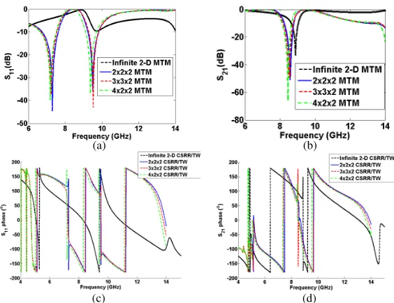
To verify the above explanation of the infinite periodicity truncation of the MTM structure, three different 3-D MTM structures with truncated periodicity of sizes 2×2×2, 3×3×2, and 4×2×2, in addition to one 2-D MTM structure with infinite periodicity are designed and simulated in CST software. The scattering parameters of the MTM structures with infinite and truncated periodicities are traced as shown in Fig. 7. It is clear that the return loss and the transmission characteristics of the 3-D truncated MTM structures are better than their counterparts of the 2-D infinite periodicity MTM structure. These improvements are because of the multilayer used in the case of the truncated MTM structure, while in the case of the infinite periodicity, one layer of 2-D infinite periodicity is used. Then the effective parameters of all the MTM structures are extracted and plotted for ambiguity branch parameterpof 0 [46] as shown in Fig. 8. Fig. 8 illustrates that the infinite periodicity truncation of the MTM structure does not destroy the negative effective parameters of the MTM structure, and the structure still has negative values for real effective permittivity, real effective permeability and real refractive index as shown in Figs. 8(a), 8(c) and 8(e), respectively, around 10 GHz. Also, the imaginary parts of the effective permittivity and permeability have DC offset values far away from resonance and peak at resonance which shows that the structure has a physical Lorentzian response. Furthermore, the optimum dimensions of the MTM lens structure will be chosen such that the return loss of the antenna is not destroyed as a result of the capacitive and inductive coupling presented by the MTM lens to the conventional antenna. This will be studied in the coming section.
(a) (b)
(c) (d)
Figure 7. Magnitude of the scattering parameters of the MTM structure with truncated periodicity by building the MTM lens from 3-D structure with finite sizes of 2×2×2, 3×3×2 and 4×2×2. (a)
(e) (f)
(c) (d)
(a) (b)
Figure 8. The extracted effective parameters of the MTM structure truncated periodicity by building the MTM lens from 3-D structure with finite sizes of 2×2×2, 3×3×2 and4×2×2 with ambiguity branch parameter p of 0 [40], (a) real part of effective permittivity (ε), (b) imaginary part of effective permittivity (ε), (c) real part of effective permeability (μ), (d) imaginary part of effective permeability (μ), (e) real part of refractive index (n), and (f) imaginary part of refractive index (n).
2.3. Design and Simulation of 10 GHz Patch Antenna Incorporated with CSRR/TW MTM Lens in Front of the Patch
Here, the proposed patch antenna incorporated with MTM is analyzed, simulated and optimized using CST software. The proposed antenna operates at 10 GHz, and the MTM lens is optimized to have a negative permeability, negative permittivity and negative refractive index in a wideband around the 10 GHz. The antenna is optimized by changing the size of the MTM lens and the separation between the MTM lens and the patch. Figs. 9(a) and 9(b) show the return loss and radiation gain at 10 GHz of the proposed antenna at 10 mm separation distance hs between the patch and the MTM lens bottom side and at different MTM lens sizes. The separation distance between each two 2D MTM layers is 2 mm.
Furthermore, the effect of the patch and MTM lens separation on the radiation and impedance matching parameters are studied by fixing the size of the MTM lens at 3×3×2 inx,y andzdirections, respectively and changing the separation distance hs from 6 mm to 12 mm by step size of 2 mm. It
(a) (b)
(c)
Figure 9. (a) The simulated return loss and (b) the simulatedE-plane and (c)H-plane gain at 10 GHz of the proposed antenna with and without MTM lens of different sizes and at 10 mm separation distance
hs between the patch and the MTM lens.
(a) (b)
(c)
Figure 10. (a) The simulated return loss and the simulated (b) E-plane and (c) H-plane gains at 10 GHz of the proposed antenna with and without MTM lens of size 3×3×2 and different separation distanceshs between the patch and the MTM lens.
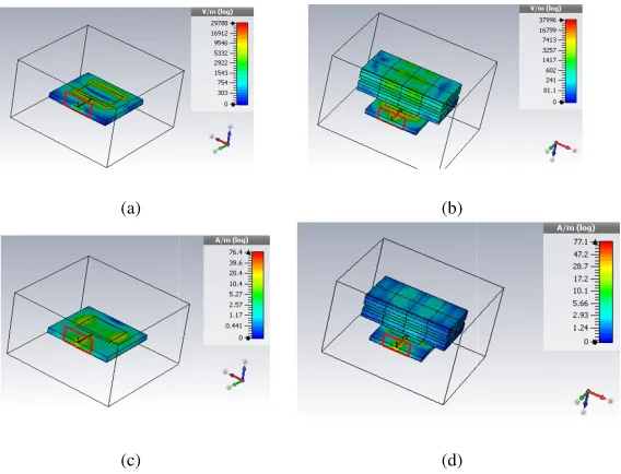
without MTM lens at 10 GHz are plotted as shown in Fig. 11. It is clear that by placing the MTM lens of size 3×3×2 and identifying the convergence mesh criteria in the CST, the electric field E
(a)
(c)
(b)
(d)
Figure 11. Near field of the proposed antenna without and with MTM lens at 10 GHz, (a) E-field without MTM lens, (b) E-field with MTM lens, (c) H-field without MTM lens and (d) H-field with MTM lens.
(a)
(c)
(b)
(d)
Figure 12. The fabricated antenna, (a) conventional patch and top view of CSRR/TW 2-D periodic structure of size 4×4×2, (b) conventional patch and bottom view of CSRR/TW 2-D periodic structure, 3-D view of the proposed antenna, and (d) top view of the proposed antenna incorporated with MTM lens.
2.4. Fabrication and Measurement
For experimental validation, the proposed antenna resonating at 10 GHz as well as the CSRR/TW MTM lens has been fabricated as shown in Fig. 12. The fabrication is done using wet etching technique on an RT/Duroid 5880 substrate for both the patch antenna and the MTM with a relative permittivity of
εr= 2.2 and thickness ofh= 1.57 mm. The return lossesS11for the simulated and fabricated antennas
with and without MTM structure are shown in Fig. 13. Furthermore, the effect of the separation distance between the patch and the MTM lens of size 3×3×2, and the effect of the MTM lens size at fixed separation hS of 8 mm on the impedance matching of the antenna are illustrated as shown
in Fig. 13(a) and Fig. 13(b), respectively. The measured bandwidths of the patch antenna with and without MTM are approximately the same, around 400 MHz. However, the measured return loss of the 10 GHz proposed antenna incorporated with MTM lens placed on the patch at a separation distance of 8 mm and of size 3×3×2 is improved from −13 dB to −30 dB. The separation distance between each two 2D MTM layers is 2 mm. By comparing Figs. 9(a), 9(b) and 13, it is clear that the simulated and measured results prove that the antenna return loss is improved by adding MTM lens. The minor difference between the simulated and measured results is due to the soldering of the SMA connector and the misalignment of the MTM lens at the top of the patch.
Furthermore, both E- and H-plane radiation patterns at 10 GHz proposed antenna with and without MTM are measured for different MTM lenses of sizes 4×2×2 and 3×3×2 and fixed separation
hS of 10 mm between the patch and the bottom side of the MTM lens as shown in Fig. 14. However, the
simulated E- andH-plane radiation patterns at 10 GHz proposed antenna with and without MTM are plotted in the same figure. It is clear from Fig. 14 that the measured results prove that the radiation pattern of the antenna with MTM is more focused than that without MTM lens, although there is a deviation between the conventional measured and simulatedH-plane radiation patterns which may be due to the soldering of the SMA connector which may distort the radiation pattern.
(a) (b)
Figure 13. The measured and simulated return loss of the proposed antenna with and without MTM lens (conventional): (a) at different separation between the MTM lens and the patch and 3×3×2 MTM lens size, and (b) at different MTM lens sizes and separation distance of 10 mm between the patch and the MTM lens.
(a) (b)
Figure 14. Measured and simulated radiation pattern at 10 GHz of the proposed antenna with and without MTM lens for different MTM lens sizes, (a) E-plane and (b)H-plane and fixed separation hS
of 10 mm between the patch and the MTM lens.
Figure 15. Comparison between the measured and the simulated gains of the proposed antenna with and without MTM lens of different sizes and fixed separation hs of 10 mm between the patch and the MTM lens.
2.5. Major Contribution of This Work
There are two main reasons behind this research. Firstly, the published papers which used the MTM as a cover to improve the performance of the patch antenna such as [18, 50] suffer from two problems of mechanical stability and large size. Regarding the mechanical stability problem, in [18] the MTM layers are placed vertically on the patch substrate which cause difficulty in the alignment and low mechanical stability. In terms of the large size problem, in [50] a large size and bulky MTM structure consists of a 3-D array of thin wires is used to focus the radiated waves. Furthermore, the two mentioned literature papers focus on neither the NRI extraction nor the oblique response of the MTM structure and did not show the transmission and reflection coefficients of the structure at different orientation angles of the MTM structure with respect to the excitation source. In order to employ the NRI MTM structure as a lens, it should have good transmission and reflection coefficients as well as NRI around the frequency of interest which is 10 GHz in this paper. In this paper, the two mentioned problems are solved. For example, in terms of mechanical stability point of view, the MTM structure is composed of NRI CSRR/TWs MTM layers placed at the top of the patch in parallel arrangement to the patch substrate with foam spacers which results in rigid and mechanically stable antennas. However, it is not necessary to stack many layers of the CSRR/TWs MTM in front of the patch to improve the gain, and two layers are enough to improve the gain from 7 dB to 11.6 dB. Thus, the proposed antenna is rigid, light and mechanically stable and easy in fabrication, since the MTM lens consists of one layer or multi-layers of 2-D CSRR/TWs structure rather than 3-D array of thin wires [50].
Secondly, this work will service our future plan of proposing a THz optical antenna incorporated with MTM lens for heart beat measurement [51] and high resolution imaging systems. Here, it has been illustrated that in the microwave regime, if the NRI CSRR/TWs MTM structure is excited obliquely, it will have a good transmission and reflection as well as NRI for all angles. So, if the structure is scaled down in dimension and up in frequency in order to develop a MTM lens in the THz regime, it can focus the radiated THz waves from the optical THz antenna instead of using bulky silicon lens [52]. However, the proposed antenna can be optically tuned by rotating the optical antenna as well as the lens with respect to the excitation laser beam, and the MTM structure will still have NRI for all angles. By this way, it is possible to propose an efficient THz optically-tuned optical antenna incorporated with MTM lens. Furthermore, by studying the futures of the MTM structures through their oblique response, it is possible to optimize and proposed novel MTM lenses for the THz optical antennas.
3. CONCLUSION
In this paper, the performance of a 10 GHz patch antenna is greatly improved by beam focusing when it is integrated with a 3-D CSRRs/TWs periodic structure employing a MTM lens. The MTM lens was suspended above the patch antenna through foam spacer with electric permittivity closed to air; the MTM lens focused the radiated EM waves of the patch antenna in a narrow area. The 2-D infinite periodicity CSRR/TWs MTM structure is designed and simulated in CST software, and the effective parameters are extracted. The results illustrate that the MTM structure has negative values for the real part of the effective parameters. Furthermore, the angular independency of the CSRR/TWs MTM structure with infinite 2-D periodicity has been verified by rotating the MTM structure from 0 to 180 degrees with respect to the excitation probe of the TEM waves. The results show that MTM structure has negative effective parameters and good reflection and transmission characteristics in a wide band of angles around 10 GHz, which prove that the MTM acts as lens. In addition, the infinite periodicity truncation of the MTM structure is also studied by designing and simulating 3-D MTM structures with finite sizes of 2×2×2, 3×3×2, and 4×2×2. The results show that the MTM structure truncation has no impacts on both the MTM lens negative effective parameters and homogeneity.
MTM periodic structure employing the MTM lens. These improvements in the antenna parameters validate the proposed concept of beam focusing using 3-D periodic structure of CSRRs/TWs, which employs the MTM lens, without significant modification in the matching methodology of the patch antenna. Furthermore, we have demonstrated the validity of the above properties by CST software EM simulator and experimentally at 10 GHz and shown that at this frequency the antenna gain is improved by 4.6 dB, while the beam width is reduced from 75 to 41 degrees which validate the concept of beam focusing using CSRR/TWs MTM lens. The measured and simulated results show an improvement in the return loss by about−20 dB for the antenna incorporated with MTM lens of size 2×2×2 although it increases when 3×3×2 and 4×2×2 MTM lens sizes are used. This improvement due to the reactance coming from the electric and magnetic couplings between the patch and MTM lens, and the coupling between different parts of the MTM lens itself which result in a reactance term added to the antenna input impedance. As a future work, the idea of gain improvement of the patch antenna incorporated with the NRI MTM lens can be extended to THz frequency range to be used for short distance wireless communication link, particularly in the biomedical application and inside the satellite to reduce the wiring complexity of the satellite system and. However, the MTM lens can replace the bulky silicon lens used in the THz optical antennas to focus the radiated beam and improve the antenna gain.
REFERENCES
1. Collin, R.,Field Theory of Guided Waves, McGraw-Hill, New York, 1960.
2. Gauthier, G., A. Courtay, and G. Rebeiz, “Microstrip antennas on synthesized low dielectric-constant substrates,”IEEE Transactions on Antennas and Propagation, Vol. 45, No. 8, 1310–1314, 1997.
3. Colburn, J. and Y. Rahmat-Samii, “Patch antennas on externally perforated high dielectric constant substrates,”IEEE Transactions on Antennas and Propagation, Vol. 47, No. 12, 1785–1794, 1999. 4. Kokotoff, D., R. Waterhouse, C. Birtcher, and J. Aberle, “Annular ring coupled circular patch with
enhanced performance,”Electron. Lett., Vol. 33, No. 24, 2000, 1997.
5. Rojas, R. and K. Lee, “Surface wave control using nonperiodic parasitic strips in printed antennas,”
IEE Proceedings — Microwaves, Antennas and Propagation, Vol. 148, No. 1, 25, 2001.
6. Bhattacharyya, A., “Characteristics of space and surface waves in a multilayered structure (microstrip antennas),” IEEE Transactions on Antennas and Propagation, Vol. 40, No. 8, 1231– 1240, 1990.
7. Jackson, D., J. Williams, A. Bhattacharyya, R. Smith, S. Buchheit, and S. Long, “Microstrip patch designs that do not excite surface waves,”IEEE Transactions on Antennas and Propagation, Vol. 41, No. 8, 1026–1037, 1993.
8. Khayat, M., J. Williams, D. Jackson, and S. Long, “Mutual coupling between reduced surface-wave microstrip antennas,” IEEE Transactions on Antennas and Propagation, Vol. 48, No. 10, 1581–1593, 2000.
9. Pendry, J., “Negative refraction makes a perfect lens,”Phys. Rev. Lett., Vol. 85, No. 18, 4166–4169, 2000.
10. Weng, Z., N. Wang, Y. Jiao, and F. Zhang, “A directive patch antenna with metamaterial structure,” Microwave and Optical Technology Letters, Vol. 49, No. 2, 456–459, 2006.
11. Liu, Y. and X. Zhao, “Enhanced patch antenna performances using dendritic structure metamaterials,” Microwave and Optical Technology Letters, Vol. 51, No. 7, 1732–1740, 2009. 12. Smith, D., W. Padilla, D. Vier, S. Nemat-Nasser, and S. Schultz, “Composite medium with
simultaneously negative permeability and permittivity,” Phys. Rev. Lett., Vol. 84, No. 18, 4184– 4187, 2000.
13. Smith, D. and N. Kroll, “Negative refractive index in left-handed materials,” Phys. Rev. Lett., Vol. 85, No. 14, 2933–2936, 2000.
15. Grbic, A. and G. Eleftheriades, “Periodic analysis of a 2-D negative refractive index transmission line structure,”IEEE Transactions on Antennas and Propagation, Vol. 51, No. 10, 2604–2611, 2003. 16. Chen, L., S. He, and L. Shen, “Finite-size effects of a left-handed material slab on the image
quality,”Phys. Rev. Lett., Vol. 92, No. 10, 2004.
17. Veselago, V. G., “The electrodynamics of substances with simultaneously negative values ofεand
μ,”Soviet Physics Uspekhi, Vol. 10, No. 4, 509, 1968.
18. Majid, H. A., M. K. Abd Rahim, and T. Masri, “Microstrip antenna’s gain enhancement using left-handed metamaterial structure,” Progress In Electromagnetics Research M, Vol. 8, 235–247, 2009.
19. Alici, K., F. Bilotti, L. Vegni, and E. Ozbay, “Optimization and tunability of deep subwavelength resonators for metamaterial applications: Complete enhanced transmission through a subwavelength aperture,”Opt. Express, Vol. 17, No. 8, 5933, 2009.
20. Alici, K. and E. Ozbay, “Characterization and tilted response of a fishnet metamaterial operating at 100 GHz,” Journal of Physics D: Applied Physics, Vol. 41, No. 13, 135011, 2008.
21. Gil, M., J. Bonache, J. Selga, J. Garcia-Garcia, and F. Martin, “High-pass filters implemented by composite right/left handed (CRLH) transmission lines based on complementary split rings resonators (CSRRs),” PIERS Online, Vol. 3, No. 3, 251–253, 2007.
22. Buell, K., H. Mosallaei, and K. Sarabandi, “A substrate for small patch antennas providing tunable miniaturization factors,”IEEE Transactions on Microwave Theory and Techniques, Vol. 54, No. 1, 135–146, 2006.
23. Alici, K. and E. Ozbay, “Electrically small split ring resonator antennas,”J. Appl. Phys., Vol. 101, No. 8, 083104, 2007.
24. Alu, A., F. Bilotti, N. Engheta, and L. Vegni, “Subwavelength, compact, resonant patch antennas loaded with metamaterials,” IEEE Transactions on Antennas and Propagation, Vol. 55, No. 1, 13–25, 2007.
25. Pirhadi, A., F. Keshmiri, M. Hakkak, and M. Tayarani, “Analysis and design of dual band high directive EBG resonator antenna using square loop FSS as superstrate layer,” Progress In Electromagnetics Research, Vol. 70, 1–20, 2007.
26. Lee, Y., J. Yeo, K. Ko, R. Mittra, Y. Lee, and W. Park, “A novel design technique for control of defect frequencies of an electromagnetic bandgap (EBG) superstrate for dual-band directivity enhancement,”Microwave and Optical Technology Letters, Vol. 42, No. 1, 25–31, 2004.
27. Erentok, A., P. Luljak, and R. Ziolkowski, “Characterization of a volumetric metamaterial realization of an artificial magnetic conductor for antenna applications,” IEEE Transactions on Antennas and Propagation, Vol. 53, No. 1, 160–172, 2005.
28. Burokur, S., M. Latrach, and S. Toutain, “Theoretical investigation of a circular patch antenna in the presence of a left-handed medium,” Antennas and Wireless Propagation Letters, Vol. 4, No. 1, 183–186, 2005.
29. Li, B., B. Wu, and C. H. Liang, “Study on high gain circular waveguide array antenna with metamaterial structure,”Progress In Electromagnetics Research, Vol. 60, 207–219, 2006.
30. Burghignoli, P., G. Lovat, F. Capolino, D. R. Jackson, and D. R. Wilton, “Directive leaky-wave radiation from a dipole source in a wire-medium slab,” IEEE Transactions on Antennas and Propagation, Vol. 56, No. 5, 1329–1339, 2008.
31. El-Nawawy, M., A. A. Allam, and A. Korzec, “The design of a 0.35 THz microstrip patch antenna on LTCC substrate,”Electrical and Electronic Engineering, Vol. 1, No. 1, 1–4, 2011.
32. Turpin, J., J. Bossard, K. Morgan, D. Werner, and P. Werner, “Reconfigurable and tunable metamaterials: A review of the theory and applications,” International Journal of Antennas and Propagation, Vol. 2014, 1–18, 2014.
34. Ziolkowski, R. W., “Metamaterial-based antennas: Research and developments,” IEICE Transactions on Electronics, Vol. 89, No. 8, 1267–1275, 2006.
35. Enoch, S., G. Tayeb , P. Sabouroux, N. Gu´erin, and P. Vincent, “A metamaterial for directive emission,”Physical Review Letters, Vol. 89, 213902, 2002.
36. Xu, H., Z. Zhao, Y. Lv, C. Du, and X. Luo, “Metamaterial superstrate and electromagnetic band-gap substrate for high directive antenna,” Int. J. Infrared Milli. Waves, Vol. 29, 493–498, 2008. 37. Ju, J., D. kim, W. J. Lee, and J. I. Choi “Wideband high-gain antenna using metamaterial
superstrate with the zero refractive index,” Microwave and Optical Tech. Lett., Vol. 51, No. 8, 1973–1976, 2009.
38. Temelkuaran, B., M. Bayindir, E. Ozbay, R. Biswas, M. Sigalas, G. Tuttle, and K. M. Ho, “Photonic crystal-based resonant antenna with a very high directivity,” Journal of Applied Physics, Vol. 87, 603–605, 2000.
39. Al`u, A., F. Bilotti, N. Engheta, and L. Vegni, “Metamaterial covers over a small aperture,”IEEE Transactions on Antennas and Propagation, Vol. 54, No. 6, 1632–1643, Jun. 2006.
40. Tang, M., S. Xiao, D. Wang, J. Xiong, K. Chen, and B. Wang, “Negative index of reflection in planar metamaterial composed of single split-ring resonators,” Applied Computational Electromagnetics Society (ACES) Journal, Vol. 26, No. 3, 250–258, Mar. 2011.
41. Woodley, J., M. Wheeler, and M. Mojahedi, “Left-handed and right-handed metamaterials composed of split ring resonators and strip wires,”Physical Review E, Vol. 71, No. 6, 2005. 42. Kamtongdee, C. and N. Wongkasem, “A novel design of compact 2.4 GHz microstrip
antennas,” IEEE 6th International Conference on Electrical Engineering/Electronics, Computer,
Telecommunications and Information Technology, 2009, ECTI-CON 2009, Vol. 2, 766–769,
May 2009.
43. Bancroft, R., “Microstrip and printed antenna design,” The Institution of Engineering and Technology, 2009.
44. Pues, H. and A. V Capelle, “Accurate transmission-line model for the rectangular microstrip antenna,” Proc. IEEE, Vol. 131, No. 6, 334–340, Dec. 1984.
45. Chen, X., T. Grzegorczyk, B. Wu, J. Pacheco, and J. Kong, “Robust method to retrieve the constitutive effective parameters of metamaterials,” Physical Review E, Vol. 70, No. 1, 2004. 46. Arslanagic, S., T. V. Hansen, N. A. Mortensen, A. H. Gregersen, O. Sigmund, R. W. Ziolkowski,
and O. Breinbjerg, “A review of the scattering-parameter extraction method with clarification of ambiguity issues in relation to metamaterial homogenization,” IEEE Antennas and Propagation Magazine, Vol. 55, No. 2, 91–106, 2013.
47. Nicolson, A. M. and G. F. Ross, “Measurement of the intrinsic properties of materials by time-domain techniques,” IEEE Transactions on Instrumentation and Measurement, Vol. 19, No. 4, 377–382, 1970.
48. Boughriet, A. H., C. Legrand, and A. Chapoton, “Noniterative stable transmission/reflection method for low-loss material complex permittivity determination,” IEEE Transactions on Microwave Theory and Techniques, Vol. 45, No. 1, 52–57, 1997.
49. Campione, S., S. Steshenko, M. Albani, and F. Capolino, “Complex modes and effective refractive index in 3D periodic arrays of plasmonic nanospheres,” Optics Express, Vol. 19, No. 27, 26027– 26043, 2011.
50. Hu, J., C. S. Yan, and Q. C. Lin, “A new patch antenna with metamaterial cover,” Journal of Zhejiang University SCIENCE A, Vol. 7 No. 1, 89–94, 2006.
51. Kurzweil-Segev, Y., M. Brodsky, A. Polsman, E. Safrai, Y. Feldman, S. Einav, and P. Ben Ishai, “Remote monitoring of phasic heart rate changes from the palm,”IEEE Transactions on Terahertz Science and Technology, Vol. 4, No. 5, 618–623, 2014.

![Figure 3. The CSRR/TWs infinite 2-D periodicity MTM structure with negative effective parameterseffective permeability (around the fundamental resonance frequency of 10 GHz, extracted at unambiguity branch parameterp = 0 [46], (a) S-parameters magnitude, (b) S-parameters phase, (c) effective permittivity (ε), (d)μ) and (e) refractive index (n).](https://thumb-us.123doks.com/thumbv2/123dok_us/1883710.1245617/6.612.161.448.84.415/periodicity-parameterseective-permeability-fundamental-unambiguity-parameterp-parameters-permittivity.webp)
![Figure 4. The 2-D infinite periodicity CSRR/TWs MTM structure with negative effective parameterseffective permeability (around the first harmonic resonance frequency of 10 GHz, extracted at unambiguity branch parameterp of 0 [46], (a) S-parameters magnitude, (b) S-parameters phase, (c) effective permittivity (ε), (d)μ) and (e) refractive index (n).](https://thumb-us.123doks.com/thumbv2/123dok_us/1883710.1245617/7.612.160.448.332.663/periodicity-eective-parameterseective-permeability-unambiguity-parameterp-parameters-permittivity.webp)

![Figure 6. The 2-D infinite periodicity CSRR/TWs MTM structure with negative effective parametersreal part of refractive index ((of 0 [46] and at different rotational angles of 0, 45, and 180 degrees with respect to the excitation TEMwave direction, (a) real part of effective permittivity (around the first harmonic resonance frequency of 10 GHz, extracted with ambiguity branch parameter pε′), (b) imaginary part of effective permittivityε′′), (c) real part of effective permeability (μ′), (d) imaginary part of effective permeability (μ′′), (e)n′), and (f) imaginary part of refractive index (n′′).](https://thumb-us.123doks.com/thumbv2/123dok_us/1883710.1245617/9.612.161.448.76.410/periodicity-parametersreal-rotational-eective-permittivity-permittivitye-permeability-permeability.webp)
![Figure 8. The extracted effective parameters of the MTM structure truncated periodicity by buildingpermittivity ((the MTM lens from 3-D structure with finite sizes of 2 × 2 × 2, 3 × 3 × 2 and4 × 2 × 2 with ambiguitybranch parameter p of 0 [40], (a) real part of effective permittivity (ε′), (b) imaginary part of effectiveε′′), (c) real part of effective permeability (μ′), (d) imaginary part of effective permeabilityμ′′), (e) real part of refractive index (n′), and (f) imaginary part of refractive index (n′′).](https://thumb-us.123doks.com/thumbv2/123dok_us/1883710.1245617/11.612.163.448.79.411/eective-periodicity-buildingpermittivity-ambiguitybranch-permittivity-eectivee-permeability-permeabilitym.webp)