8
Physical Coding Sub Layer Implementation of Common
Public Radio Interface
T.Tirumala Rao
1, P.V.L.Suvarchala
2, M.Harikrishna Reddy
31Department of ECE, Amrita Sai Institute of Science and Technology, Paritala, Krishna (dt), A.P, India. 2Associate.proffesor Department of ECE, Amrita Sai Institute of Science and Technology, Paritala, Krishna (dt), A.P,
India.
3ASIC Verification Engineer, Appex Semiconductors, Mahadevapura, Bangalore, Karnataka, India.
Email: [email protected], [email protected]2
,
[email protected]Abstract: -In radio communication systems for high speed data transmission and to avoid unbalanced code flow we use PCS. This paper mainly deals with encoding and decoding techniques used in Physical Coding Sub layer. In this PCS layer we use encoding, decoding, mux, mode select register and synchronization state machine. So, in the transmitter side we will deal with how to encode the data and what are the rules to follow to encode the data. Similarly, in the receiver side we will deal with how to decode the data and what are the rules to follow to decode the data. The proposed circuit is simulated in Modelism and the results obtained are presented in this paper.
Index Terms: - Common Public Radio Interface, Physical coding sub layer, 8B/10B algorithm, 16B/20B algorithm, 32B/40B algorithm, Synchronization State Machine, Multiplexer.
1. INTRODUCTION
Radio base station system is composed of two basic subsystems, Radio Equipment Control (REC) and Radio Equipment (RE). The interface between REC and Higher layers is Network interface and the interface between RE and Air is Air interface. The Common Public Radio Interface (CPRI) is an internal communication link between two radio base stations REC and RE. This interface supports different data rates ranging from 614.4Mbits/sec to 12165.12Mbits/sec. In this interface we have several layers, but main concentration is in bottom two layers which are physical layer(layer 1) and datalink layer(layer 2). In Cpri interface the bottom layer i.e., Physical Layer plays a crucial role. Inside this Physical Layer we have Physical Coding Sub layer (PCS) and SERDES. The main purpose of PCS is to encode in the transmitter side and to decode in the receiver side. SERDES will do parallel to serial conversion in the transmitter side and serial to parallel conversion in the receiver side.
2. PHYSICAL CODING SUBLAYER
In ISO-OSI we have seven layers, in those layers bottom layer is physical layer. Physical coding sublayer (PCS) is present inside the physical layer. It will perform the following actions.
It will encode the incoming data during transmission.
It will decode the data during reception.
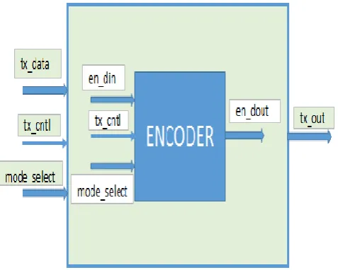
2.1. PCS Transmitter:
In PCS transmitter we have encoder. In encoder we have encoding schemes and mux. Mux will perform the mode select operation.
9
The default operation is 8b to 10b encoding.
Figure 2. PCS transmitter block diagram
2.1.1 Encoder:
The main purpose of encoder is to maintain the enough no.of transitions between 0’s and 1’s in the serial line. While performing encoding operation we have to consider disparity rules. The encoding schemes present inside this encoder are 8b to 10b, 16b to 20b
Running disparity at the end of any sub-block is positive if the sub-block contains more ones than zeros. It is also positive at the end of the six-bit sub-block if the six-bit sub-block is 000111, and it is positive at the end of the four-bit sub-block if the four-bit sub-block is 0011.
Running disparity at the end of any sub-block is negative if the sub-block contains more
zeros than ones. It is also negative at the end of the six-bit sub-block if the six-bit sub-block is 111000, and it is negative at the end of the four-bit sub-block if the four-bit sub-block is 1100.
Otherwise, running disparity at the end of the sub-block is the same as at the beginning of the sub-block.
ii. 8b to 10b encoding:
In 8b to 10b encoding it will convert the 8bit incoming data to 10bit data by using the valid code group tables given in IEEE 802.3 Standard.
Table 1. Some valid data code groups
Table 2.valid special code groups
iii. 16b to 20b encoding:
In 16b to 20b encoding scheme we will convert 16bit input data into 20bit data by using two 8b to 10b sub blocks.
iv. 32b to 40b encoding:
10
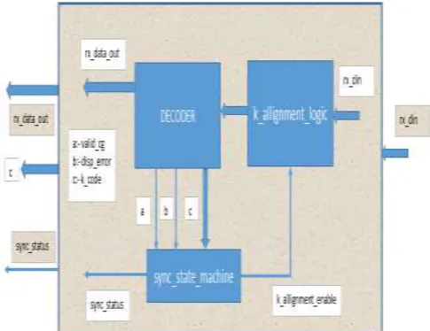
2.2. PCS Receiver:
In PCS receiver we have decoder, state_machine, k_allignment_logic. In decoder we have decoding schemes and mux. Mux will perform the
The default operation is 10b to 8b decoding.
Figure 3: PCS receiver block diagram
2.2.1 Decoder:
The main purpose of the decoder is to decode the incoming data. In this we have three decoding schemes. In decoder output we have 3 status signals. They are k_code, valid_cg and disparity_error.
If the input code group of the decoder is k28.1, k28.5 and k28.7 then k_code is 1, otherwise k_code is 0.
If the input code group of the decoder is present in the code group table given in IEEE 802.3 section-3 clause-36 and produce valid decoded data depending on input disparity then that code group is valid_codegroup else it is invalid
If the 10-bit code group has more ones than zeros or more zeros than ones then the disparity_output must be opposite to
disparity_input then that 10-bit code group has no disparity_error. Otherwise it has disparity_error.
In 10b to 8b decoding scheme we will convert 10bit data into 8bit data by using valid code group tables shown in figure 3 and figure 4.
ii. 20b to 16b decoding:
In 20b to 16b decoding scheme we will convert 20bit data into 16bit data by using two 10b to 8b sub blocks.
iii. 40b to 32b decoding:
In 40b to 32b decoding scheme we will convert 40bit data into 32bit data by using four 10b to 8b sub blocks.
2.2.2. Synchronization state machine:
It will monitor the consistency of the incoming data by detecting the pattern K D D D. For detecting the pattern it has the following steps.
Initially upon reset we will go to loss_of_sync state and make sync_acquired signal 0. If we detect K in this state we will go to comma_detect_1 state. If not we will go to loss_of_sync state.
In comma_detect_1 state if we detect D then we will go to comma_detect_2 state. If not we will go to loss_of_sync state.
In comma_detect_2 state if we detect D then we will go to comma_detect_3 state. If not we will go to loss_of_sync state.
In comma_detect_3 state if we detect D then we will go to sync_acquired_ state and make sync_acquired signal 1. If not we will go to loss_of_sync state.
11
2.2.3 K_allignment_logic:
K_allignment_logic is used to detect the k_code groups and to align them in LSB byte position. Initially k_allignment_enable signal is high in state_machine because of sync_failure. After detecting k then k_allignment_enable signal will become low
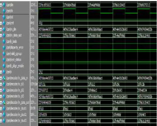
3. SIMULATION RESULTS
We have simulated the code using Questa Sim simulater. The simulation results are shown in figures 4, 5, 6 and 7.
Figure 4: PCS in mode 00
Figure 5: PCS in mode 01
Figure 6: PCS in mode 10
Figure 7: PCS in mode 11
4. CONCLUSION
In this paper we design the 8b to 10b, 16b to 20b and 32b to 40b encoding schemes for PCS transmission and 10b to 8b, 20b to 16b and 40b to 32b decoding schemes and sync_state_machine and k_allignment_logic for the PCS reception. These logics can be used for high speed fiber communication systems and where ever physical layer is present there we can use these logics.
12 Radio and Telecom etc. We can use this one where ever
we required a physical layer.
REFERENCES
[1] CPRI Specification V6.1 (2014-07-01). [2] IEEE 802.3-2008_section3.
[3] IEEE-Verilog-LRM.
[4] J. Bhasker, A Verilog HDL Primer, second edition. [5] Andrew S. Tanenbaum, COMPUTER
NETWORKS, 4th edition, Pearson Education, Inc, 2003.
[6] M. Morris Mano, Digital Design with an introduction to Verilog HDL, fifth edition.