Analysis of Seismic and Wind Effect on Steel Silo
Supporting Structures
Ashwini Bidari
1, K.N.Vishwanath
2M. Tech student1 , Dept of Civil Engineering1 , DSCE , Bangalore ,Karnataka, India1 Associate Professor2 , Dept of Civil Engineering2 , DSCE , Bangalore, Karnataka, India2
E-mail: bidariashwini@gmail.com1, vishuknv@yahoo.com2
Abstract - India’s economic growth is contingent upon the growth of the Indian steel industry. Consumption of steel is taken to be an indicator of economic development. In steel plants, steel silos are used for the storage of bulk materials. However, steel silos differ principally from their concrete counterparts in physical properties like the high strength per unit weight and ductility. The high yield and ultimate strength result in slender sections. Being ductile the steel structures give sufficient advance warning before failure by way of excessive deformations. Steel silo is elevated and supported by frames. This paper describes the analysis and design of high-rise steel building frame with braced and without braced under effect of wind and earthquake using SAP2000 and also to compare the response of braced and unbraced building which subjected to horizontal or lateral loading system. Dynamic analysis is carried out by using Equivalent Static method and Response spectrum method for earthquake zone V as per Indian code. The results in terms of Natural period, Design Base shear, lateral Displacements are compared for the different silo supporting models considered in the present study. The braced system gives the economical results compared to unbraced system in terms of frequency and displacement
Index Terms - Silo, Linear bracing system, Moment-Resisting frame, Dynamic action, SAP2000
1. INTRODUCTION
Industrial buildings are generally designed as enclosures that provide functional space for internal activities, which may involve use of overhead cranes or suspended equipments. Various structural forms have been developed over the last 30 years that optimise the cost of the steel structure in relation to the space provided. Both structural and seismic engineering are involved in the design of new industrial facilities, but have certainly a primary role in the evaluation and upgrading of existing plants. Furthermore, their design is very standardized worldwide and thus they represent a challenging topic in the contexts of an industrial risk assessment related to external hazards like earthquakes and wind. In fact, their dynamic response is not trivial, since material/structure interactions are relevant and influence the susceptibility to seismic damage. Therefore in any Industrial structures the storage of bulk solids is an important aspect. Bin is a structure meant for storing bulk material in vertical direction with outlets for withdrawal either by gravity alone or by gravity assisted by flow promoting devices. A bin is of two kinds viz, bunker and silo. A shallow structure whose cross section is square or rectangular in plan is called bunker, and tall structure whose cross section is circular or polygonal is called silo. In this study, silo is an inclusive term for all steel structures for the storage of bulk solids. Steel silos in common use, may be ground-supported or elevated. Typical elevated
cylindrical shell and a conical hopper and they could be elevated and supported by frames or reinforced concrete columns or on discrete supports. As a result, silos are designed and evaluated as special structures. The purpose of this study is to compare the analysis of seismic and wind effects on two supporting structures for steel silo and these are linear lateral force resisting systems. These systems are, Special concentrically braced frame (SCBF) and special moment-resisting frame (SMRF). These system provides several advantages as compare to other lateral load resisting system because it has ductility and the energy absorption capacity which make these system suitable to be used as wind and seismic resistant element in the steel structures.
2. OBJECTIVES OF THE STUDY
• To compare the response of braced and unbraced building subjected to lateral loads. • To determine the natural time period, total
base shear distribution and lateral displacement, using linear static method and response spectrum analysis as per IS:1893(Part1)-2002.
• To compare the cost effectiveness of Special concentrically braced frame (SCBF) over special moment-resisting frame (SMRF) for building structures.
3. DETAILS OF THE STRUCTURES
3.1. Assumptions
The assumptions are made as follows:
In the present study the structure considered is a Day bin (silo) building at Pellet plant at a place called BHUJ for Jindal steel and power limited. The bin provided in this building
[image:2.595.261.329.262.426.2]stores the raw materials required for one day for processing. The bin receives the raw materials from a conveyor the gallery of which is having the next support at 24m from the building. Day bin building accommodates head pulley and drive of in-coming conveyor. The incoming conveyors are located at higher level at El. + 36.2m as shown in fig 2.1. The total height of the building is 40.9m. The plan dimension of the building is 9mx9m. The study is carried out on the same building plan for both braced and unbraced frame and the loading on both types of building kept same. Silo load is considered acting on frame where it got supported to the building.
Fig. 1. Steel silo supported on frame with conveyor gallery
3.2. Modelling and Analysis
The silo supporting structures are modeled and analysed by SAP2000. SAP2000 is anything that has a fixed form inputs, meaning that material properties, equilibrium and compatibility equation, energy and work principals, incompatible elements, boundary conditions, analysis methods, design
principals and philosophy. Also, the information about building and site condition, meaning that the number of frames with spacing of columns longitudinal direction and transverse direction. The number of stories and types of diaphragm, usage of building, soil condition, wind and seismicity condition. The typical buildings are compared for dynamic analysis with different methods.
.
[image:2.595.197.406.583.733.2]Fig. 3. Model II
3.3. Structural Loads
Different structural loads that the building typically must carry are
- Dead load - Live load - Equipment load - wind load - Seismic load
Forces that act vertically are gravity loads like dead load, live load, Equipment load. Forces that act horizontally, such as wind and seismic events require lateral load resisting systems to be built into structures. As lateral loads are applied to a structure, horizontal diaphragms (floors and roofs) transfer the load to the lateral load resisting system.
4. DESCRIPTION FOR LOADING
The loading on the structure is considered as per following calculations
Density of Iron ore taken as 29.42 kN/m3 I. On Roof
a. Live Load = 75 kg/sqm b. Dead Load = 30 kg/sqm II. Floor Load
a. Dead Load of grating = 40 kg/sqm
b. Live Load = 500 kg/sqm III. Belt tensions at head pulley
a. T1 = 25000 kg (tight side) b. T2 = 6500 kg (slack side) IV. Conveyor Gallery Load (assuming next
support of the gallery at 24m from the building)
a. Dead Load = 1600 kg/m
b. Dead load per support on the building=1600X0.5X12=4800 kg c. Live Load due to material in the
d. Live load on walk way each side = 300 kg/m
e. Live load per support on the building = ((400X0.5)+300)X12 = 6000 kg
V. Conveyor Load (inside the building) a. Dead load of conveyor=400 kg/m b. Dead load of conveyor per side =
400X0.5 = 200 kg/m
c. Live load of conveyor due to material = 400 kg/m
d. Live load due material per side = 400X0.5 = 200 kg/m
VI. Equipment Load
a. Drive/Head pulley and pulley support = 5000 kg
b. Drive load (motor, gear box & supporting frames) = 6500 kg c. Monorail = 2500 kg
VII. Chute Load
a. Dead Load = 6000 kg
b. Material Load under choked condition = 20000 kg
VIII. Earthquake Forces Data: Earthquake load for the structure has been calculated as per IS-1893-2002:
i. Zone (Z) =V
ii. Response Reduction Factor ( RF ) For Braced Frame = 4
iii. Response Reduction Factor ( RF ) For Unbraced Frame = 5
iv. Importance Factor ( I ) = 1 v. Soil condition = Medium vi. Zone factor = 0.36 vii. Type of Structures = 2 viii. Damping Ratio (DM) = 0.02
IX. Wind Forces Data: Wind load for the structure has been calculated as per IS 875 (part-3):
Risk coefficient (K1 factor) = 1 Topography (k3 factor) = 1 X. Load Combinations:
Load combinations for design purpose shall be the one that produces maximum forces in the members and consequently maximum stresses. When the effect of wind or earthquake load is taken into account, the permissible stresses specified may be
[image:4.595.71.283.213.589.2]exceeded by 33.33 percent. In the present study, to take care of the increase in stress, the working load is reduced by 33.33 percent and the combined stress ratio is maintained at unity. The following load combinations are considered for the analysis and design as per IS 800 1984.
Table 3.1 Load combinations as per IS 1893 (Part I) -2002
Load
Combination Load Factors
Gravity Analysis
DL+LL DL+LL+EQUIP
Wind
0.75(DD+LL+EQUIP+WIND-X)
0.75(DD+LL+EQUIP+WIND-Y)
0.675DL+0.75WIND-X 0.675DL+0.75WIND-Y
Equivalent Static Analysis
0.75(DD+LL+EQUIP+EQX) 0.75(DD+LL+EQUIP+EQY)
0.675DL+0.75EQX 0.675DL+0.75EQY
Response Spectrum Analysis
0.75(DD+LL+EQUIP+RSX) 0.75(DD+LL+EQUIP+RSY)
0.675DL+0.75RSX 0.675DL+0.75RSY
Where
DL= Dead Load LL= Live Load
EQUIP = Equipment load
WIND-X, WIND-Y = Wind load in X & Y direction respectively
EQX, EQX = Earthquake load in X & Y direction respectively
RSX, RSY = Response Spectrum Load in X & Y direction respectively
5. RESULTS AND DISCUSSIONS
The results are presented for each of the building model considered, for the static and dynamic
analyses carried out by SAP2000 package. Both wind and earthquakes cause dynamic action on building. But, design for wind forces and for earthquake effects are distinctly different. The intuitive philosophy of structural design uses force as the basis, which is consistent in wind design, wherein the building is subjected to a pressure on its exposed surface area; this is force-type loading. However, in earthquake design, the building is subjected to random motion of the ground at its base, which induces inertia forces in the building that in turn cause stresses; this is displacement-type loading.
In this work, analysis of symmetrical braced and unbraced building is carried out for both actions and found out which dynamic action is governing. Comparison of different performance characteristics are made to check the performance of unbraced and braced building. Bracing is done with different angle sections. The results are in terms of natural periods of vibrations, lateral displacements, and total base shear distribution for different building models. These are presented and compared.
5.1 Natural Period
Fig. 4. Comparison of Time period values of braced and unbraced frame
5.2 Base Shear
Base shear is obtained from both wind and seismic analysis, in which the seismic effect is governed over wind effect as shown in Figs 4.2-4.5. In the response spectrum method the design of total base shear (Vb) is made equal to the base shear obtained from equivalent static method Vb as per IS:
[image:5.595.146.449.400.559.2]1893(Part1)-2002 by applying the scaling factor. In seismic analysis the base shear produce in X and Y direction is same because stiffness of building is same in both direction. As the stiffness of bracing sections increases, the base shear in building also increases in both directions. Fig. 4.4 and Fig.4.5 shows that the base shear in bracing system is more as compared to unbraced system
Fig. 5. Comparison of Base Shear for Model I and Model II in X direction 0
0.2 0.4 0.6 0.8 1 1.2 1.4 1.6 1.8
1 2 3 4 5 6 7 8 9 10 11 12 13 14 15
T
im
e
p
er
iod
Braced
Unbraced
Modes
0
200
400
600
800
1000
Model I
Model II
Wind-X
Models
B
as
e
she
ar
(
K
N
)
0 200 400 600 800 1000
Model I Model II
Wind-Y
B
as
e
she
ar
(
K
N
)
Fig. 6. Comparison of Base Shear for Model I and Model II in Y direction
Fig. 7. Comparison of Base Shear for Model I and Model II in X direction
Fig. 8. Comparison of Base Shear for Model I and Model II in Y direction
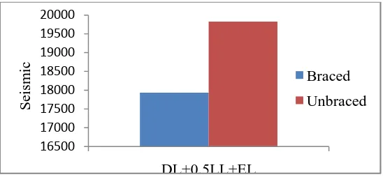
5.3 Seismic Weight
Mass of a building that is effective in lateral oscillation during earthquake shaking is called the seismic mass (weight) of the building. It is the sum of its seismic masses at different floor levels. Seismic mass at each floor level is equal to full dead load plus appropriate fraction of live load. The fraction of live load depends on the intensity of the live load and how it is connected to the floor.
[image:6.595.162.436.619.746.2]Seismic design codes of each country/region provide fractions of live loads to be considered for design of buildings to be built in that country/region. Therefore in the present study, according to Indian code practice we have considered 50% of live load for seismic weight as shown in Table 5.4. It is seen in table 5.4 clearly the seismic weight is more for unbraced frame as compare to braced frame.
Fig. 9. Comparison of seismic weight for braced and unbraced frame 0
500 1000 1500 2000 2500
Braced Frame Unbraced Frame
EQX
RSX
MODELS
B
as
e
S
he
ar
0 500 1000 1500 2000 2500
Braced Frame Unbraced Frame
EQY
RSY
MODELS
B
as
e
S
he
ar
16500 17000 17500 18000 18500 19000 19500 20000
DL+0.5LL+EL
Braced
Unbraced
S
ei
sm
5.4 Lateral Displacement
Lateral displacement profiles for Braced and Unbraced buildings models obtained by both wind and seismic effect. In seismic, equivalent static
[image:7.595.151.448.159.325.2]method (ESM) and response spectrum method (RSM) are shown in following figures that give the values of lateral displacement along longitudinal directionand traverse direction.
Fig. 10. Lateral displacement of model I and Model II for winding loading
i
n X direction [image:7.595.158.449.371.537.2]Fig. 11. Lateral displacement of model I and Model II for winding loading in Y direction
0 10 20 30 40 50 60
1 2 3 4
L
at
er
al
D
is
pl
ac
em
ent
(
m
m
)
Model I
Model II
Floor Level
0 5 10 15 20 25 30 35 40 45
1 2 3 4
MODEL I
MODEL II
L
at
er
al
D
is
pl
ac
em
ent
(m
m
)
Levels of Frames
0 10 20 30 40 50 60 70
1 2 3 4
MODEL I
MODEL II
L
at
er
al
D
is
pl
ac
em
ent
(
m
m
)
[image:7.595.148.449.587.744.2]Fig. 13. Lateral displacement of model I and Model II for RSX
Fig. 14. Lateral displacement of model I and Model II for EQY
Fig. 15. Lateral displacement of model I and Model II for RSY 0
2 4 6 8 10 12
1 2 3 4
MODEL I
MODEL II
Floor Level
L
at
er
al
D
is
pl
ac
em
ent
(
m
m
)
0 10 20 30 40 50 60
1 2 3 4
MODEL I
MODEL II
L
at
er
al
D
is
pl
ac
em
ent
(m
m
)
Floor Level
0 5 10 15 20 25 30
1 2 3 4
MODEL I
MODEL II
L
at
er
al
D
is
pl
ac
em
ent
(
m
m
)
[image:8.595.143.454.541.734.2]6. CONCLUSIONS
On the basis of the present study, following conclusions are made:
1. The frequency of the building is increased for about 45% by providing bracing system. Thus providing bracing system increases the stability of the structure, especially in earth quake prone areas or under dynamic loading. 2. The Base shear is more for seismic effect as
compare to wind effect. So the seismic governs over wind in zone V. Base shear is increased for braced compare to unbraced system. 3. The displacement for braced and unbraced
structure is well within permissible limit. The lateral displacement of braced building decreases as compare to the unbraced building which indicates that the overall response of the building decreases.
4. The displacement of the structure is generally found be reduced by providing bracing frame for supporting silo structure.
5. The braced system gives the economical results compared to unbraced system in terms of frequency and displacement.
REFERENCES
[1] Manish S. Takey "SEISMIC RESPONSE OF STEEL BUILDING WITH LINEAR BRACING SYSTEM (A Software Approach)" International Journal of Electronics, Communication & Soft Computing Science and Engineering ISSN: 2277-9477, Volume 2, Issue 1.
[2] Nateghi .F and Yakhchalian .M, "Seismic Behavior of Silos With Different Height to Diameter Ratios Considering Granular Material structure Interaction" Structural Engineering Research Center, International Institute of Earthquake Engineering and Seismology, Tehran, Iran December 15, 201. [3] Anand Adi "Parametric Study On Dynamic
Response Of Silo" International Journal of
Engineering Research & Technology (IJERT) Vol. 2 Issue 7, July - 2013.
[4] Choi .H "Comparison of the Seismic Response of Steel Buildings Incorporating Self-Centering Energy Dissipative Braces, Buckling Restrained Braced and Moment Resisting Frames" The 14th World Conference on Earthquake Engineering October 12-17, 2008, Beijing, China.
[5] Hongyu Li "ANALYSIS OF STEEL SILO STRUCTURES ON DISCRETE SUPPORTS" Department of Civil Engineering & Building Science The University of Edinburgh Edinburgh, Scotland, UK September 1994. [6] Julien Richard "SEISMIC DESIGN AND
RESPONSE OF HEAVY INDUSTRIAL STEEL BUILDING" 3rd ECCOMAS Thematic Conference on Computational Methods in Structural Dynamics and Earthquake Engineering M. Papadrakakis, M. Fragiadakis, V. Plevris (eds.) Corfu, Greece, 25–28 May 2011.
[7] Bahador Bagheri "Comparative Study of the Static and Dynamic Analysis of Multi-Storey Irregular Building" World Academy of Science, Engineering and Technology Vol:6 2012-11-27.
[8] Syed Rehan" Study of Seismic and Wind Effect on Multi Storey R.C.C. Steel and Composite Building"International Journal of Engineering and Innovative Technology (IJEIT) Volume 3, Issue 12, June 2014. [9] Fatih Bazman "STIFFENING OF THIN
CYLINDRICAL SILO SHELL AGAINST BUCKLING LOADS" The 12th International Conference on Machine Design and Production 05 - 08 September 2006, Kuşadası, Turkey.
[10]IS: 800 - 1984 - General Construction In Steel - Code of Practice.
[11]IS: 875 (Part 3) - 1987: Code of Practice for Design Loads (Other Than Earthquake) for Buildings and Structures- Wind Loads. [12]IS: 1893(part 1)-2002 - Criteria for earthquake