18th International Conference on Structural Mechanics in Reactor Technology (SMiRT 18) Beijing, China, August 7-12,2005 SMiRT18-G05-4
APPLICATION
OF THREE DIMENSIONAL CRACK ANALYSIS USING
FINITE ELEMENT ALTERNATING METHOD
Tae Soon Kim*
Department of Safety Engineering, Chungbuk National University, Korea
Phone: +82-43-264-2460, Fax: +82-43-264-2460
E-mail: [email protected]
Sang Yun Park
Department of Safety Engineering,
Chungbuk National University, Korea
E-mail: [email protected]
Jai Hak Park
Department of Safety Engineering,
Chungbuk National University, Korea
E-mail: [email protected]
Chi Yong Park
Korea Electric Power Research
Institute, Korea
E-mail: [email protected]
Tae Eun Jin
Korea Power Engineering Company, lnc.,
Korea
E-mail: [email protected]
ABSTRACT
Many analysis methods, including finite element method, have been suggested and used for assessing the integrity of cracked structures. In the paper, in order to analyze arbitrary three dimensional cracks in an infinite body, the finite element alternating method is extended. The cracks are modeled as a distribution of displacement discontinuities by the displacement discontinuity method and the symmetric Galerkin boundary element method. In order to apply the suggested method to the structure of industrial facilities, an elbow including a semi-elliptical surface crack, in the nuclear power plant, is analyzed. As the result of the application, it is demonstrated that the finite element alternating method can be used effectively to evaluate the structural integrity of industrial facilities
Keywords: three dimensional crack, finite element alternating method, stress intensity factor, fatigue crack.
1. INTRODUCTION
It is well known that most of the cracks occurred in the industrial structure equipments including nuclear components are three dimensional cracks. In structural integrity assessment and damage tolerance analysis, the calculation of fracture mechanics parameters for arbitrary three-dimensional surface and internal cracks remains an important task (Atluri, 1997). To obtain the solution of this problem, the finite element method (FEM) and the theoretical solution for internal cracks were combined adequately. The analyses of fracture mechanics using the finite element methods are well established. In addition, the use of energetic methods and in particular the equivalent domain integral method allows to obtain fracture mechanics parameters with acceptable accuracy (Park, Kim and Atluri, 2000 and Nikishkov, Park and Atluri, 2001) The finite element method to the analysis of three-dimensional cracks, however, needs a lot of time and high costs in the mesh generation.
traditional boundary element approach. The SGBEM is characterized by the weakly singular kernels. After a special transformation, which removes the singularity from kernels, the boundary element matrices can be integrated with the use of usual Gaussian rule.
The FEAM is the convenient and efficient method to analyze the three-dimensional cracks embedded in an infinite or a finite body because the method has the property that the uncracked body and cracks are modeled independently each other. The obvious disadvantage of this approach is the reduced size of matrices responsible for interaction between finite element for the crack and for the uncracked body and small solution time. By using the methods, the analysis of three-dimensional planar or non-planar cracks embedded in an infinite or a finite body can be performed more efficiently and more accurately. And the FEAM is particularly efficient for modeling of fatigue crack growth since the finite element mesh for the uncracked body and the boundary mesh for the crack are completely independent.
With the use of the proposed procedure the stress intensity factors are calculated about some of three dimensional cracks embedded in infinite and finite body and compared with the published solutions (Park, Kim and Atluri, 2000). And the stress intensity factors for arbitrarily shaped three-dimensional cracks are calculated to simulate the crack growth. In the following, in order to apply the suggested method to the structure of industrial facilities, the crack growth simulation for the elbow including a semi-elliptical surface crack, in the nuclear power plant, has been performed. As the result of the application, it is demonstrated that the finite element alternating method can be used effectively to evaluate the structural integrity of industrial facilities.
2. FINITE ELEMENT ALTERNATING METHOD
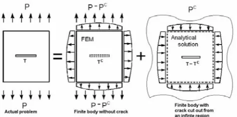
The basic concept of the finite element alternating method can be illustrated by the principle of superposition. Consider a body with a center crack subject to a boundary traction P, as illustrated in Fig. 1
The solution for a finite body with a crack is obtained as a superposition of two models: 1. finite element model for a finite body under external loading, without a crack;
2. an infinite body with a crack modeled by the symmetric Galerkin boundary element method.
The load PC is the fictitious force applied to the load P in the finite element to account for the presence of a crack. The traction TC is the correction applied to the traction T in the infinite body with a crack to account for the finite boundary of the actual problem. While this can be cone with a direct procedure, the alternating method provides for a more efficient solution, without assembling the joint Symmetric Galerkin boundary element method and finite element method matrix.
Fig. 1. Superposition principle upon which the FEAM is based
The finite element alternating method alternates between the finite element solution for an uncracked body and the displacement discontinuity method solution for a crack in an infinite body. The advanced algorithm is developed by the modification of the iteration procedure proposed by Nikishkov and Atluri (1994) first for elasto-plastic analysis using the finite element alternating method.
3. THEORETICAL FORMULATION
3.1 Analytical Solution Using Displacement Discontinuity
Consider an infinite three-dimensional body containing arbitrarily three-dimensional cracks of arbitrary geometry. A distributed load is applied at the crack surface. The crack can be described by a distribution of displacement discontinuity with components (Li and Mear, 1998, Xu and Ortiz, 1993).
∫
∫ ∫
− = − S k k S jb j S j ii C D u dS dS u u t dS
u
D *( ) ( ) ( ) ( ) ( ) *( ) ( )
z z z ξ ξ z ξ
z αβ β
α (Eq.1)
Here
S
=
S
+ is one of crack surfaces,u
i are displacement discontinuities for the crack surface,u
*i arethe components of a continuous test function and
t
k are crack face tractions. The two-point weakly singular kernel is given by the following expression.⎟⎟ ⎠ ⎞ ⎜⎜ ⎝ ⎛ − − + − − = α β β α αβ αβ β α
δ
ζ
ζ
δ
δ
δ
νδ
δ
δ
ν
ν
π
μ
2 2 ) 1 ( ) 1 ( 4 ) ( r rC ij ζ i j i j ij i j (Eq.2)
Assume the crack that is partitioned into boundary elements. Displacement discontinuities and tractions are defined at element nodes, and are interpolated inside the elements with the use of shape functionsNa .
ia a
i ia a
i
N
u
t
N
t
u
=
(
η
1,
η
2)
,
=
(
η
1,
η
2)
(Eq.3)Where,
i
= 1, 2, 3 is the global coordinate subscript,a
is the node number,η
1,
η
2 are element local coordinates. With the use of a parametric representation of displacement discontinuities and tractions, we can rewrite the integral equation Eq. 1 in the following discretized form.∫
∫ ∫
= − S iq q a S jb b a S ji D N z D N dS dS z u N N dS z t
Cαβ α ( ) β (
ξ
) (ξ
) ( ) ( ) (Eq.4)Using the integral equation Eq. 4, displacement discontinuities at element nodes of the crack are defined, and then the stress intensity factors can be calculated from their values.
3.2 Analysis of Fatigue Crack Growth
For calculating fatigue crack growth increment, generally Paris’s (1960) equation or Forman's (1967) equation is used . Paris’s equation are given by
( )
K n.C dN
da = Δ (Eq.5 )
where da/dN is the crack growth per cycle, ΔK is the stress intensity factor range, C and n are material constants that are determined experimentally. According to Eq. 5, the fatigue crack growth rate depends only on ΔK.
Forman’s equation is given by:
( )
(
R)
K KK C dN da Δ − Δ = c n -1
(Eq. 6 )
Where, R is the stress ratio in cyclic loading and Kc is the fracture toughness for the material and thickness
of interest. Crack growth direction is determined by using the maximum principal stress criterion (Erdogan, 1963). Crack extension angle
θ
m is determined from the following equation:(
3cos 1)
0.sin +K − =
In calculating
Δ
K
in Eq. 6, we use the equivalent stress intensity factor which is defined by:( )
2 sin 2 cos 3 2
cos3 2 m m II
m I eq
I K K
K = θ − θ θ . (Eq.8 )
4. APPLICATION
4.1 Elbow Pipe with a Surface Crack
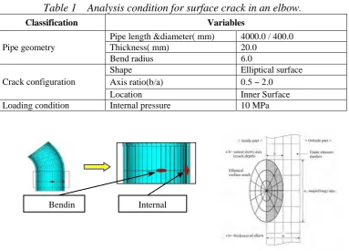
For the application of the method, an elbow pipe of nuclear power plants is selected in which a semi-elliptical surface crack is included. The length of the elbow is 4000 mm, the diameter 400 mm and the thickness 20 mm. And the bending curvature of the elbow is 6 times to diameter of the elbow pipe. The material type is the carbon steel pipe, which is generally used as the piping material of non-safety classes in pressurized water reactor(PWR) power plants. Details of analytical condition related in the crack and elbow are represented in Table 1. ABQUS(2001), the commercial finite element program, is used to obtain the loading condition of the crack and internal pressure is 10 MPa.
The pipe geometry as well as crack configuration and loading condition are presented in Table 1. The Paris material fatigue model was chosen to simulate fatigue crack growth, where C=3.0E-13 and n=3.0 are material parameters as recommended by Maddox (1991) for a wide rage of structural steels. The initial ratio a/b of semi- elliptical surface crack is 0.5, and the ratio of the crack depth and pipe thickness is 1/5. The crack configuration, crack mesh and other conditions are presented in Fig. 3. The nodal stress data gained by using ABAQUS is applied as residual force in order to obtain the surface traction on the crack faces. And then, the stress intensity factors KI for the crack front nodes are calculated.
Table 1 Analysis condition for surface crack in an elbow
.Classification Variables Pipe length &diameter( mm) 4000.0 / 400.0
Thickness( mm) 20.0 Pipe geometry
Bend radius 6.0
Shape Elliptical surface Axis ratio(b/a) 0.5 ~ 2.0
Crack configuration
Location Inner Surface
Loading condition Internal pressure 10 MPa
Fig. 2 Mesh configuration for a semi-elliptical surface crack in an elbow.
4.2 Analysis of Elliptical Surface Crack in an Elbow
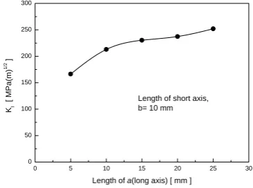
In order to calculate stress intensity factors for surface cracks a semi-elliptical surface crack is considered as shown in Fig. 2. The crack is located in the weld zone which has many problems related to the damage of pipes. Fig. 3 represents the stress intensity factors calculated in the condition that the miner axial length of the crack
b
is constant and the major axial length
a
is increased case by case. The initial major axial length of the crack is 10 mm. In this case the stress intensity factors in the crack tip are increased linearly but the increments are gradually decreased as shown in Fig. 4.Next, the stress intensity factors are calculated when the major axial length of the crack
a
(20 mm) is constant and the miner axial lengthb
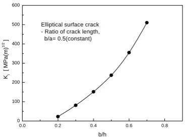
is increased case by case. As shown in Fig. 5, the stress intensity factors in the crack tip are increased radically in contrast to the above case.Finally, we calculated the stress intensity factors of the crack when both the length of major axis and the miner axis are increased case by case. This analysis is aimed to observe the variation of stress intensity factors according to fatigue crack growth and Fig. 6 represents the results with respect to the ratio of crack length to crack thickness. Considering the above analysis for the fatigue growth of elliptical crack, the results show the variation of stress intensity factors would be placed between those of Fig. 5 and Fig. 6.
4.3 Simulation of Fatigue Crack Growth
A semi-elliptical surface crack, located to the axial direction of the elbow pipe, is considered to simulate the fatigue crack growth of the surface crack near the weld zone. The type of loads applied to the elbow is the internal pressure and the stress intensity factors for Mode I are calculated. Aspect ratio of the semi-elliptical surface crack is 0.5 and the initial crack length of the crack is 4 mm. Other conditions such as crack shape and crack meshes are identical to those of Fig. 3.
Paris equation is applied to calculate fatigue crack growth rate, which explains typical fatigue crack growth behavior in metals. Material constants composing the equation are equalto the above values. Based on the stress intensity factor obtained by Paris equation, the crack tip is transformed according to increments in each node. The results are presented in Fig. 7 with respect of the angle of crack nodes. As shown in the results, stress intensity factors are maximized in the 90° location and are minimized in the both sides of the crack. According to the increments of stress intensity factors calculated at the crack tip of an elliptical crack, embedded in an elbow under cyclic loading condition, the elliptical crack is advanced toward the center of thickness. The crack growing process of the original crack is presented in Fig. 8 step by step.
45 90 135
0 50 100 150 200 250 300
KI
[ M
P
a
(m
)
1/
2 ]
Angle θ [ degrees ] b= 10.0 a= 5.0 b= 10.0 a= 10.0 b= 10.0 a= 15.0 b= 10.0 a= 20.0 b= 10.0 a= 25.0
0 5 10 15 20 25 30
0 50 100 150 200 250 300
Length of short axis, b= 10 mm KI
[
MPa
(m
)
1/
2 ]
Length of a(long axis) [ mm ]
Fig. 3 SIF’s according to angle of the crack Fig. 4 SIF’s according to the major length
0.2 0.4 0.6 0.8 0
100 200 300 400 500 600 700
Elbow thickness, h= 20.0mm Length of short axis, a= 20.0mm
KI
[
MP
a(m)
1/
2 ]
b/h
0.0 0.2 0.4 0.6 0.8
0 100 200 300 400 500 600
Elliptical surface crack - Ratio of crack length, b/a= 0.5(constant)
KI
[
MP
a
(m)
1/
2 ]
b/h
Fig. 5 SIF’s according to b/h for a Fig. 6 SIF’s according to b/h for a
semi-elliptical crack in an elbow. semi-elliptical surface crack in an elbow.
45 60 75 90 105 120 135
0 20 40 60 80 100 120
KI
[ MPa
(m
)
1/
2 ]
Angle β [degrees] 1st growth 2nd growth 3rd growth 4th growth 5th growth
h
<Outside> <Inside>
Origin. crack 1st crack 2nd crack 3rd crack 4th crack 5th crack
Fig. 7 SIF’s of a semi-elliptical crack in an Fig. 8 Growth of an elliptical crack in an
elbow under cyclic loading condition. elbow under cyclic loading condition.
According to the stress intensity factors, the crack front lines are advanced to new positions with scaling to the specified maximum crack advance
da
max . A new layer of elements would be newly defined by the relationship of old and new crack front lines. Five crack advancements were performed and the shape of each crack after crack propagations is too given in Fig. 8.5. CONCLUSIONS
The finite element alternating method has been used for the analysis of three dimensional cracks in infinite or finite bodies. Especially, since the finite element mesh for the uncracked body and the boundary mesh for the crack are completely independent, the method is particularly efficient for modeling of fatigue crack growth.
The suggested method is applied to the structure of industrial facilities, an elbow including a semi-elliptical surface crack, in the nuclear power plant. We calculated the stress intensity factors at the crack tip case by case when both the length of the major and the miner axis of the cracks are changed. As the result of the analyses, it is demonstrated that the finite element alternating method can be used effectively to analyze the three dimensional cracks in the structure of industrial facilities.
REFERENCES
S.N. Atluri, (1997), “Structural Integrity and Durability”, Tech Science Press, Forsyth.
J.H. Park, T.S. Kim, S.N. Atluri, (2000), Transactions of the KSME, Vol.24, No.4, pp.982-990.
G. P. Nikishkov, J. H. Park, S. N. Atluri, (2001), Com. Modeling in Eng.& Sci., Vol.2, No.3, pp.401-422. G.P. Nikishkov and S.N. Atluri, (1994), Computational Mechanics, Vol.13, pp.427-442.
J.H. Park and S.N. Atluri, (1992) , Computational Mechanics, Vol.13, pp.189-203. S. Li and M. E. Mear, (1998), Int. J. Fracture, Vol.93, pp.87-114.
S. Li, M. E. Mear, L. Xiao, (1998), Comput. Meth. Appl. Mech. Eng., Vol.151, pp.435-459. G. Xu and M. A. Ortiz, (1993), Int. J. Numer. Meth. Eng. Vol.36, pp.3675-3701.
P. C. Paris and F. Erdogan, (1960), J. Basic Eng., Vol.85, pp.528-534.
R. G. Foreman, V. E. Keary, R. M. Engle, (1967), J. Basic Eng., Vol.89, pp.459-464. F. Erdogan and G.C. Sih, (1963), J. Basic Eng., Vol.85, pp.519-527.
Hibbitt, Karlson and Sorensen Inc., (2001), ABAQUS User's Manual.