Transactions,SMiRT-23
Manchester, United Kingdom - August 10-14, 2015
Division III, Paper ID 315
A METHOD TO ASSESS IMPACT DAMAGE USING A SMOOTHED
PARTICLE HYDRODYNAMICS AND FINITE ELEMENT COUPLED
APPROACH
Peter Gill1, Adam Toft2
1
Consultant, Amec Foster Wheeler, UK
2
Principal Consultant, Amec Foster Wheeler, UK
ABSTRACT
Following the highly unlikely event of a pressurised component failing, it is important to know the indirect consequences of failure. These include the effects of missiles generated from the failed component hitting other components within the plant. Methodologies such as the R3 assessment procedure provide formulae to calculate the missile velocity, as well as the energy required to penetrate a target. In this paper, a multi physics model is presented which enables calculation of missile velocity based on a coupling between Smooth Particle Hydrodynamics (SPH) and Finite Element Method (FEM). Investigations were performed using air as the fluid at different pressures; this enabled optimisation of the model so that it could be used to assess high pressure steam as the process fluid. A comparison between a simple hand calculated maximum acceleration, and the peak obtained from the simulation, provided a means of validating the model. Velocities obtained from the numerical method were found to be considerably lower than R3. Several reasons are suggested as to why this is the case and are justified with results from numerical simulations. In addition to this, the impact of a missile on a target was simulated using FEM with a special material model based on strain rate hardening and shear failure. The R3 impact assessment method was found to be in closer agreement with the numerical results, providing evidence that these empirical formulae are still acceptable to use in assessments. However, in order to get an accurate evaluation of missile velocity, more sophisticated methods should be used to avoid overly conservative assessments.
INTRODUCTION
A Loss of Coolant Accident (LOCA) may indirectly damage plant safety systems, including the containment boundary, by the effect of missiles generated by the LOCA. In this paper, a study to develop a modern numerical modelling technique to estimate damage by missiles is described. Smoothed Particle Hydrodynamics (SPH) has been applied to simulate the acceleration of the missile due to the fluid jet. SPH is a computational method used for simulating fluid flows that works by dividing the fluid into a set of discrete elements, referred to as particles. These particles have a spatial distance over which their properties are "smoothed" by a kernel function. This means that the physical quantity of any particle can be obtained by summing the relevant properties of all the particles which lie within the range of the kernel. Finite Element Analysis, using a material damage model, has been used to assess missile penetration depth and dynamic response of the target, based on missile velocities determined by the preceding SPH analysis.
23rd Conference on Structural Mechanics in Reactor Technology Manchester, United Kingdom - August 10-14, 2015 Division III
United Kingdom (UK). In common with other indirect consequences of failure, UK regulatory expectations are that missile damage should be determined according to best estimate. This contrasts with the estimate of direct consequences of failure, in this case the effects of loss of coolant, which are determined on a conservative basis to establish both core damage and off-site release frequency . The concluding remarks of this paper provide comment as to how application of modern techniques for assessment of missile damage may justify a reduction in current conservatisms.
MISSILE VELOCITY
Missile velocity is treated as a fluid structure interaction problem that is evaluated using SPH, which is integrated into the finite element software Abaqus 6.12 (Abaqus, 2012). The following paragraphs summarise the development and basis of SPH.
SPH was introduced by Monaghan and Gingold (1977) and is a numerical meshless method for which nodes and elements are not defined, as would be the case in conventional FEA. Instead a collection of points, referred to as particles, are defined to represent a given body. These have a characteristic length over which the fluid properties are smoothed by a kernel function. The kernel is established such that it has a value of one at its centre and zero at the perimeter, with the result that each particle interacts only with particles within its kernel radius. The work by Zsis (2013) and also Croaker (2011) provide examples of recent publications that have applied SPH to impact and fluid-structure interaction problems respectively.
SPH applies the Navier–Stokes equations, expressed in Lagrangian form, to describe fluid behaviour as follows:
ɏ
ൌ െɏǤ
(1)
ൌ െ
ͳ
ɏ ɋଶ
(2)
where ρ is the density, u is the velocity, t is the time, p is the pressure, ν0 is the viscosity and F is the body force. These equations arise from Newton's of fluid motion, and incorporate an assumption that stress in the fluid is the sum of a diffusing viscous term, proportional to the gradient of velocity, and a pressure term, hence describing viscous flow. These equations are discretized with a grid of particles leading to the SPH equations for conservation of mass, momentum and energy, as follows:
Conservation of Mass
ۃɏ
ۄ ൌ ୨ሺ୧୨ െ ୨ሻǤ୧୨
(3)
Conservation of Momentum
ۃ
ۄ ൌ ୨ሺ ୨ ɏ୨ଶെ
୧ ɏ୧ଶሻ ୨
Ǥ୧୧୨ (4)
Conservation of Energy
ۃ ۄ ൌ
ͳ
ʹ ୨ሺ ୨ ɏ୨ଶെ
୧ ɏ୧ଶሻ ୨
୧୨Ǥ୧୧୨ (5)
Wij is the smoothing kernel for particles i and j. The smoothing kernel used in this implementation is a
cubic spline. So that the mass, mi, of each equation does not, in general, change the following expression
must hold:
୧ ൌ Ͳ
(6)
23rd Conference on Structural Mechanics in Reactor Technology Manchester, United Kingdom - August 10-14, 2015 Division III
ሺǡ ሻ ൌ Ƚୈ
ە ۔
ۓଵିଷଶ୯మାଷସ୯యஸ୯ழଵ ଵ
ସሺଶି୯ሻయଵஸ୯ழଶ ୯ஹଶ
(7)
ൌ୧െ ୨ (8)
where: ri is the location of the ith particle,
αD is a normalization factor to ensure the integral of the kernel itself
reproduces unity, defined as: 1D: 2/3h
2D: 10/(7πh2) 3D: 1/(πh3)
and h is the smoothing length.
It is also possible to specify quadratic and quintic kernels. A plot of the cubic spline is given in Fig. 1, where the symmetry is illustrated, and the kernels =0 beyond ±2h.
Figure 1. Cubic Spline for smoothing kernel in SPH simulations
SPH model
23rd Conference on Structural Mechanics in Reactor Technology Manchester, United Kingdom - August 10-14, 2015 Division III
Figure 2. SPH Missile Velocity Model
To accurately represent vessel geometry the finite element model comprises four-node general-purpose shell elements (S4R), with reduced integration and hourglass control, with a number of three-node triangular general purpose elements (S3) at the boundaries. Both elements are specified as having finite membrane strains.
A rigid body condition is imposed on the vessel which is fixed with an encastre boundary condition. The missile is modelled using eight-node brick elements with reduced integration. For estimation of missile velocity, the missile is also treated as a rigid body but is not constrained in any degree of freedom. The resolution of the mesh is refined in the break region, both in the pressure vessel and the missile, in order that the geometry of the circular opening and the missile shape are well defined. All structural elements are linear. The SPH particle grid is created using a mesh conversion tool provided in Abaqus 6.12. A finite element mesh using 4-node linear tetrahedron elements is converted to a grid of particles, where each element is replaced by a particle (PC3D). The initial body of fluid is prescribed an initial density, which, via the ideal gas law, gives the desired pressure. Each simulation continued until the missile attained constant velocity, i.e. negligible acceleration. The missile velocity at this moment was obtained at the node closest to the centre of mass. Typically, acceleration becomes negligible within 15 microseconds.
The mass of each particle is determined by a characteristic length that is used to establish particle volume, which in turn is used to determine the mass associated with the particle. It is assumed that the nodes are distributed uniformly in space and that each particle is associated with a small cube centered at the particle. The characteristic length is half the length of the cube side. This mass is required to determine the momentum transferred to the missile from each particle collision.
23rd Conference on Structural Mechanics in Reactor Technology Manchester, United Kingdom - August 10-14, 2015 Division III
Figure 3: Acceleration vs time for various initial conditions
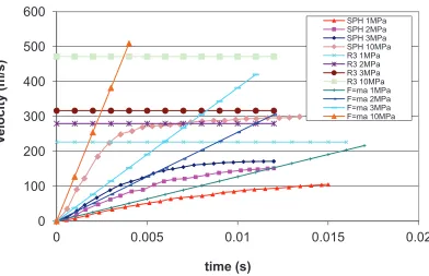
Figure 4: Velocity vs time for various initial conditions
Figure 5 shows a contour plot of density during a LOCA. Pressure rapidly reduces in the jet causing the density to decrease.
-20000 0 20000 40000 60000 80000 100000 120000 140000 160000 180000
0 0.002 0.004 0.006 0.008 0.01 0.012 0.014 0.016
A
c
c
e
le
ra
tion
(m/s
2)
time (s)
SPH 1MPa
SPH 2MPa
SPH 3MPa
SPH 10MPa
F=ma 1MPa
F=ma 2MPa
F=ma 3MPa
0
100
200
300
400
500
600
0
0.005
0.01
0.015
0.02
V
e
loc
ity
(m/s
)
time (s)
23 Conference on Structural Mechanics in Reactor Technology Manchester, United Kingdom - August 10-14, 2015 Division III
Figure 5: SPH simulation of fluid density
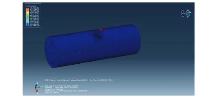
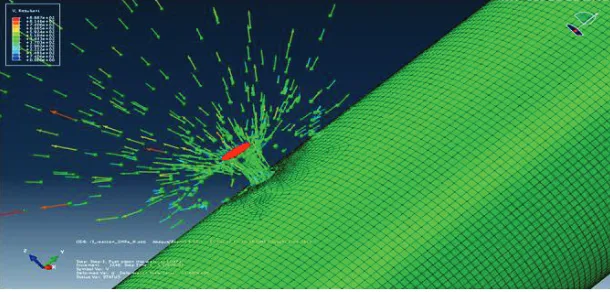
A plot of resultant velocity vectors is given in Figure 6. The direction of fluid motion is influence strongly by the presence of the missile.
Figure 6: Plot of resultant velocity vectors at each particle
Summary
The results of this first assessment show that SPH/FEA predicts missile velocities that are considerably lower than those determined using R3, EDF Energy (2003). Figure 4 illustrates typical relative
conservatism associated with SPH/FEA, R3 and Newton’s second law of motion.
The results of SPH analysis indicate that maximum acceleration of the missile occurs shortly after rupture. The results of the SPH simulations closely match those obtained in accordance with Newton’s
second law of motion in the period immediately following rupture. This confirms that SPH accurately models the very first stages of the LOCA, both in terms of fluid and missile behaviour. Beyond the instant at which peak acceleration occurs, SPH models the expected effect on missile velocity of fluid density decreasing with time, which R3 does not.
23rd Conference on Structural Mechanics in Reactor Technology Manchester, United Kingdom - August 10-14, 2015 Division III
PENETRATION ENERGY
Finite element techniques are used to assess penetration depths using a shear failure damage and strain rate hardening material model. The starting point for FEA was to consider penetrations energies, determined according to R3. An equivalent velocity is obtained for input to an initial FE calculation. If this first assessment does not indicate perforation, further analyses are conducted in which the velocity is varied in the FEA until perforation is observed.
The transfer of momentum from the missile to the target causes global deformation of the structure, as well as local damage at the impact site. Failure of the material will occur due to yielding and fracture at the regions of highest stress. A finite element model must use a failure criterion to account for these mechanisms. Using a shear failure model in Abaqus Explicit, it is possible to remove elements from the model as they fail. The material model is based on choosing an equivalent plastic strain at which failure will occur. This method is highly mesh dependent, as the minimum size of region that can be removed is the element size. Therefore, the optimum mesh must be found based on the amount of damage sustained, and computation time. Various mesh configurations are considered: square, refined, tetrahedral and tied. The simplest approach is to specify a mesh of square elements, without specifying any regions of greater refinement (in terms of mesh density) at regions of interest such as the region of the target where impact occurs. A more focussed mesh can be specified to increase the density of elements in such regions of interest, in order to more accurately model the effect of missile damage. This was chosen had it had the favourable combination of good accuracy and relatively low computational cost.
Material Model
A shear failure criteria is used where an equivalent plastic strain at failure is assumed. This is modified to account for the increase in predicted failure strains when the material is in compression. The curve recommended in R3 defines the modification factor against the triaxiality ratio, based on guidance provided in Section VIII of the ASME Boiler & Pressure Vessel Code (ASME, 2010). The material used in the models is that of 304L Austenitic Stainless Steel. Stress strain data at high strain rates is taken from (Steel Construction Institute, 2001), as shown in Table 1.
Table 1: Strain rate enhancement: 0.1%, 0.2% and 1.0% proof strengths [Ref ]
e& (s-1)
s
0.1% (N/mm2)s
0.2% (N/mm2)s
1% (N/mm2)0 269 276 316
0.0017 287 296 332
0.0025 291 300 335
0.0086 304 313 346
0.0178 311 321 352
0.088 327 338 366
7.42 372 385 404
100 403* 418* 429*
1000 433* 449* 453*
23rd Conference on Structural Mechanics in Reactor Technology Manchester, United Kingdom - August 10-14, 2015 Division III
Stress strain behaviour can be conveniently described by the Ramberg-Osgood equation:
n / 1
' K
E ÷ø
ö ç è æ s + s = e (9)
where E is the Young’s modulus in MPa and n and K’ are material constants which may be estimated
from 01 . 0 log log log log n f % 1 UTS -e s -s = (10) and n 2 % 1 10 '
K= s- (11)
Due to the large strains that arise in these analyses, the index n is calculated using the 1% proof stress and the UTS. This gives a more accurate model of material behaviour than if the standard 0.2% and 1% proof stresses were used. The strain at UTS is taken to be the failure strain, which for the material considered
here is about 50%. This is appropriate for strain levels greater than 1%. E=200GPa, ν=0.3, ρ=7800kg/m3.
The strain at UTS is chosen to be the failure strain in equation (10).
The data for strain rates of 100s-1 and 1000 s-1 in Table has been extrapolated from that given for lower strain rates, by taking a log-log plot of strain rate against strain for each stress and extending the line of best fit in a linear fashion. Engineering stress and strains are then converted into true stress and strain using the following relationships:
)
1
ln(
true
=
+
e
e
(12))
1
(
true
=
s
+
e
s
(13)A function given in Section VIII of the ASME Boiler & Pressure Vessel Code (ASME, 2010) is used to account for the change in the failure plastic strain due to triaxiality, as follows:
÷ ÷ ø ö ç ç è æ ÷ ø ö ç è æ -÷÷ ø ö çç è æ + a -e = e 3 1 M m 1 exp 2 SL uni f tri f (14)
where αSL is a material factor for the multiaxial strain limit, m2=0.75(1-R) for Stainless Steels, and R is
the ratio of minimum specified yield stress to UTS. M is the ratio of pressure stress to Mises stress:
ൌ ሺɐଵ ɐଶ ɐଷሻ
ටͳʹሾሺɐଵെ ɐଶሻଶ ሺɐଶെ ɐଷሻଶ ሺɐଷെ ɐଵሻଶሿ
(15)
were σ1, σ2and σ3 are the principle stresses at a location.
23rd Conference on Structural Mechanics in Reactor Technology Manchester, United Kingdom - August 10-14, 2015 Division III
Figure 6: Triaxiality curve from ASME
Table 2: Strain rate enhancement for UTS and failure strain (uniaxial)
e& (s-1) ߝ௨ (%) ߪ௨ (MPa)
0.0003 58.7 597 0.0159 49.3 619 0.0963 50.3 628
0.179 50.0 632
1.7 51.0 644
21.2 52.7 658
Using the uniaxial failure strain of 50%.in combination with equation (14) it is possible to generate triaxial failure strains which can then be used in the Abaqus model.
Case Study
The case considered involved a missile of diameter d, and a target of thickness t such that the ratio t/d=0.625. The initial velocity for the FE simulation was obtained from R3 calculations, then adjusted to find the critical point at which perforation occurred.
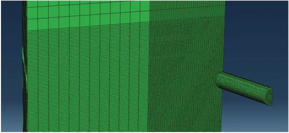
Figure 7: Mesh used for penetration assessment case study
0 2 4 6 8 10 12
-1.5 -1 -0.5 0 0.5 1 1.5
Tri
a
x
ia
li
ty
f
a
c
tor
23rd Conference on Structural Mechanics in Reactor Technology Manchester, United Kingdom - August 10-14, 2015 Division III
Figure 8: Contour plot of plastic strain at the early moments after impact
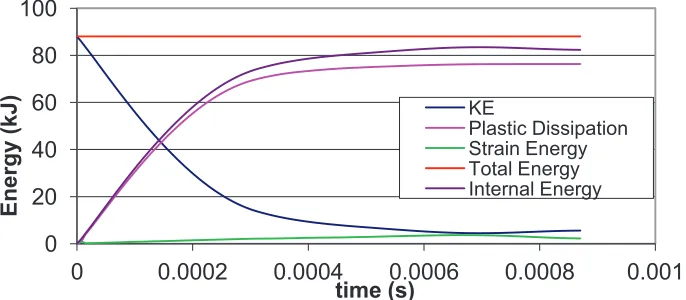
The capability of the FE model to realistically represent the transfer of energy that occurs when a missile strikes a target is illustrated in Figure 9. This shows how the total energy remains constant, and is initially comprised entirely of kinetic energy. As the impact progresses this kinetic energy transfers to plastic dissipation energy and strain energy, which causes damage to the target and deformation of the missile.
Figure 9: Plot of energies from case study
Summary
These results indicate that FEA offers a suitable alternative method to calculating penetration energy. However, assessment should be undertaken with care since there is considerable sensitivity to the specified mesh density and configuration. A strain rate hardening law and a shear failure model which takes account of triaxial effects should be included in the model. The ASME shear failure model applied in this study is a lower bound curve to experimental data, and is recommended for future application as providing a reasonable best estimate and a conservative approach. The missile model is less sensitive to mesh density than the target, however it must be sufficiently refined to accurately define the geometry of the missile and capture blunting when the target is struck.
0 20 40 60 80 100
0 0.0002 0.0004 0.0006 0.0008 0.001
E
n
ergy
(
kJ
)
time (s)
KE
23rd Conference on Structural Mechanics in Reactor Technology Manchester, United Kingdom - August 10-14, 2015 Division III
CONCLUSION
This paper presents the findings of a study to develop a modern technique for assessment of missile hazards. It follows a review of current methods to estimate damage to NPP components by LOCA generated missiles. The review identified that the usual method is given in the R3 impact assessment procedure (EDF Energy, 2003) has occasionally been applied. SPH and FEA were identified as a suitable and modern alternative technique. In common with R3, the new method considers two aspects of the problem separately: these are missile energy and target penetration. Work to develop SPH/FEA for assessment of both aspects has been described, resulting in a refined method suitable for future application. The results of new assessments have been compared with those obtained using R3.
REFERENCES
Abaqus 6.12, http://www.3ds.com
EDF Energy. (2003). R3 Impact assessment procedure.
Steel Construction Institute. (2001). Design Guide for Steel at Elevated Temperatures and High Strain Rates: (FABIG Technical Note 6).
Gingold, R. A. and Monaghan J. J. (1977). “Smoothed Particle Hydrodynamics: theory and applications
to non-spherical stars,” Royal Astronomical Society.
ASME Boiler and Pressure Vessel Code, Section VIII. (2010). Rules for Construction of Pressure Vessels, Division 2, Alternative Rules, 2011a.
Zsis I. Van Der Linden B. Giannopapa C. (2013) Towards a smoothed particle hydrodynamics algorithm for shocks through layered materials, ASME Pressure Vessels and Piping Conference, Paris
![Table 1: Strain rate enhancement: 0.1%, 0.2% and 1.0% proof strengths [Ref ]](https://thumb-us.123doks.com/thumbv2/123dok_us/1180826.1148463/7.612.92.514.505.694/table-strain-rate-enhancement-proof-strengths-ref.webp)