555-015-201
Comcode 108603994
Issue 11
December 1999
Server and System 75 and System 85
Printed in USA
Notice
Every effort was made to ensure that the information in this book was complete and accurate at the time of printing. However, information is subject to change.
Your Responsibility for Your System’s Security
Toll fraud is the unauthorized use of your telecommunications system by an unauthorized party, for example, persons other than your company’s employees, agents, subcontractors, or persons working on your company’s behalf. Note that there may be a risk of toll fraud associated with your telecommunications system and, if toll fraud occurs, it can result in substantial additional charges for your telecommunications services.
You and your system manager are responsible for the security of your system, such as programming and configuring your equipment to prevent unauthorized use. The system manager is also responsible for reading all installation, instruction, and system administration documents provided with this product in order to fully understand the features that can introduce risk of toll fraud and the steps that can be taken to reduce that risk. Lucent Technologies does not warrant that this product is immune from or will prevent unauthorized use of common-carrier
telecommunication services or facilities accessed through or connected to it. Lucent Technologies will not be responsible for any charges that result from such unauthorized use.
Federal Communications Commission Statement
Part 15: Class A Statement. This equipment has been tested and found to comply with the limits for a Class A digital device, pursuant to Part 15 of the FCC Rules. These limits are designed to provide reasonable protection against harmful interference when the equipment is operated in a commercial environment. This equipment generates, uses, and can radiate radio-frequency energy and, if not installed and used in accordance with the instructions, may cause harmful interference to radio communications. Operation of this equipment in a residential area is likely to cause harmful interference, in which case the user will be required to correct the interference at his own expense.Part 68: Network Registration Number. This equipment is registered with the FCC in accordance with Part 68 of the FCC Rules. It is identified by FCC registration number xxx.Part 68: Answer-Supervision Signaling.
Allowing this equipment to be operated in a manner that does not provide proper answer-supervision signaling is in violation of Part 68 Rules. This equipment returns answer-supervision signals to the public switched network when:
• Answered by the called station • Answered by the attendant
• Routed to a recorded announcement that can be administered by the CPE user
This equipment returns answer-supervision signals on all DID calls forwarded back to the public switched telephone network. Permissible exceptions are:
• A call is unanswered • A busy tone is received A reorder tone is received
Canadian Department of Communications (DOC) Interference Information
This digital apparatus does not exceed the Class A limits for radio noise emissions set out in the radio interference regulations of the Canadian Department of Communications.
Le Présent Appareil Nomérique n’émet pas de bruits radioélectriques dépassant les limites applicables aux appareils numériques de la class A préscrites dans le reglement sur le brouillage radioélectrique édicté par le ministére des Communications du Canada.
Trademarks
5ESS, ACCUNET, AUDIX, CALLMASTER, CentreVu, DEFINITY, DIMENSION, MERLIN, PassageWay, SPOKESMAN, TERRA NOVA, and TransTalk are registered trademarks of Lucent Technologies.
CARBON COPY Plus is a trademark of Microcom Systems Inc. E78 PLUS, CROSSTALK, and VT are registered trademarks of Digital Equipment Corporation.
Corporation.
Micro Channel is a trademark of International Business Machines Corporation.
PROCOMM PLUS is a registered trademark of Datastrom Technologies. ProLogix and TransTalk are trademarks of Lucent Technologies. RELAY GOLD is a registered trademark of Microcom Systems, Inc. SideKick is a registered trademark of Starfish Software, Inc. SMARTMODEM 2400 and SMARTCOM are trademarks of Hayes Microcomputer Products, Inc.
Ordering Information
Call: Lucent Technologies BCS Publications Center
Voice 1 800 457-1235 International Voice 317 322-6791 Fax 1 800 457-1764 International Fax 317 322-6699
Write: Lucent Technologies BCS Publications Center 2855 N. Franklin Road
Indianapolis, IN 46219
Order: Document No. 555-015-201 Issue 11, December 1999
You can be placed on a standing order list for this and other documents you may need. Standing order will enable you to automatically receive updated versions of individual documents or document sets, billed to account information that you provide. For more information on standing orders, or to be put on a list to receive future issues of this document, contact the Lucent Technologies BCS Publications Center.
For more information about Lucent Technologies documents, refer to the Business Communications Systems Publications Catalog, 555-000-010.
European Union Declaration of Conformity
Lucent Technologies Business Communications Systems declares that the equipment specified in this document conforms to the referenced European Union (EU) Directives and Harmonized Standards listed below:
EMC Directive 89/336/EEC Low-Voltage Directive 73/23/EEC
Disclaimer
Intellectual property related to this product and registered to AT&T Corporation has been transferred to Lucent Technologies Incorporated.
Any references within this text to American Telephone and Telegraph Corporation or AT&T should be interpreted as references to Lucent Technologies Incorporated. The exception is cross references to books published prior to December 31, 1996, which retain their original AT&T titles.
Heritage
Lucent Technologies — formed as a result of AT&T’s planned restructuring — designs, builds, and delivers a wide range of public and private networks, communication systems and software, consumer and business telephone systems, and microelectronics components. The world-renowned Bell Laboratories is the research and development arm for the company.
Comments
To comment on this document, return the comment card at the front of the document.
Acknowledgment
This document was prepared by Product Documentation Development, Lucent Technologies, Holmdel, NJ 07733-3030.
Contents
iii
Contents
Contents iii
1
Introduction 1-1■ The Purpose of This Manual 1-1
■ The Organization of This Manual 1-4
2
General Information 2-1■ Voice Terminals 2-1
Single-Line Voice Terminals 2-2
Multi-Appearance Voice Terminals 2-2
Facilities Common to All Voice Terminals 2-5
Buttons 2-5
Lights 2-8
Tones 2-10
Desk/Wall Mounting Arrangements 2-12
■ Adjuncts 2-12
■ Data Modules 2-15
■ PC Platform Products 2-18
■ Data Terminals 2-19
■ Technical Specifications 2-19
Call Progress Tones 2-19
External Ringing Tones 2-20
Indicator Lights Signals 2-21
3
Exposed Port Protection 3-1■ Out-of-Building Campus Stations 3-1
■ Recommended Protectors and IROB Protection 3-3
4
Adjunct Power 4-1■ Information on the Older Power Supplies 4-3
The Power Supplies Prior to the MSP-1 4-4
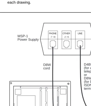
The MSP-1 Power Supply 4-5
■ The 1151A1 and 1151A2 Power Units 4-8
Contents of the 1151A1 and 1151A2 Packages
(and Comcodes) 4-9
Contents
iv
5
Administration 5-1■ Aliasing 5-2
■ Button and Feature Caveats 5-11
System 75, DEFINITY G1 and G3,
and DEFINITY ECS 5-11
System 85 and DEFINITY G2 5-12
6
Voice Terminal Features 6-17
The 6400 Series Telephones 7-1■ The 6402 and 6402D Telephones 7-2
Applications 7-4
Physical Features 7-4
Wiring Information 7-7
Appropriate Circuit Packs and Distance
Limitations 7-8
Power Requirements 7-8
Administration 7-8
Power Failure Operation 7-9
FCC Registration 7-9
UL and CSA Approval 7-9
Hearing Aid Compatible 7-10
6402 and 6402D Equipment PECs and
Comcodes 7-10
Adjuncts 7-11
Additional Documents 7-11
■ The 6408+ and
6408D+ Telephones 7-12
Applications 7-14
Physical Features 7-14
Wiring Information 7-20
Appropriate Circuit Packs and Distance
Limitations 7-21
Power Requirements 7-21
Administration 7-21
Power Failure Operation 7-22
FCC Registration 7-22
Contents
v
Hearing Aid Compatible 7-23
6408 Telephones and Equipment PECs and
Comcodes 7-23
Adjuncts 7-24
Additional Documents 7-24
■ The 6416D+ and 6416D+M Telephones 7-25
All 6416D+ and 6416D+M Telephones 7-25
Only the Modular 6416D+M Telephone 7-26
Applications 7-26
Physical Features 7-27
Wiring Information 7-33
Appropriate Circuit Packs and Distance
Limitations 7-34
Power Requirements 7-34
Administration 7-35
Power Failure Operation 7-36
FCC Registration 7-36
UL and CSA Approval 7-36
Hearing Aid Compatible 7-36
6416D+ and 6416D+M Telephones and
Equipment PECs and Comcodes 7-37
Adjuncts 7-38
Additional Documents 7-38
■ The 6424D+ and 6424D+M Telephone 7-39
All 6424D+ and 6424D+M Telephones 7-39
Only the Modular 6424D+M 7-40
Applications 7-40
Physical Features 7-41
Wiring Information 7-47
Appropriate Circuit Packs and Distance
Limitations 7-48
Power Requirements 7-48
Power Failure Operation 7-50
FCC Registration 7-50
UL and CSA Approval 7-50
Contents
vi
6424D+ and 6424D+M Equipment PECs
and Comcodes 7-51
Adjuncts 7-52
Additional Documents 7-52
8
The 7100 Series Voice Terminals 8-1■ The 7101A Voice Terminal 8-2
Applications 8-3
Physical Description 8-3
Distance Limitations 8-5
Power Requirements 8-5
Power Failure Operation 8-5
FCC Registration 8-5
Hearing Aid Compatible 8-6
7101A Equipment PECs 8-6
Adjuncts 8-6
Additional Documents 8-6
■ The 7102A and 7102 Plus Voice Terminals 8-7
Applications 8-8
Physical Description 8-8
Distance Limitations 8-10
Power Requirements 8-10
Power Failure Operation 8-10
FCC Registration 8-10
Hearing Aid Compatible 8-11
7102 Equipment PECs 8-11
Adjuncts 8-11
Additional Documents 8-11
■ The 7103A Fixed Feature Voice Terminal 8-12
Applications 8-13
Physical Description 8-13
Distance Limitations 8-15
Power Requirements 8-15
Power Failure Operation 8-15
FCC Registration 8-15
Contents
vii
7103A (Fixed Feature) Equipment PECs 8-16
Adjuncts 8-16
Additional Documents 8-16
■ The 7103A Programmable Voice Terminal 8-17
Applications 8-18
Physical Description 8-18
Distance Limitations 8-20
Power Requirements 8-20
Power Failure Operation 8-20
FCC Registration 8-20
Hearing Aid Compatible 8-21
7103A (Programmable) Equipment PECs 8-21
Adjuncts 8-21
Additional Documents 8-21
■ The 7104A Voice Terminal 8-22
Applications 8-24
Physical Description 8-24
Distance Limitations 8-26
Power Requirements 8-26
Power Failure Operation 8-26
FCC Registration 8-27
Hearing Aid Compatible 8-27
7104A Equipment PECs 8-27
Adjuncts 8-27
Additional Documents 8-27
9
The 7200 Series Voice Terminals 9-1■ The 7203H Voice Terminal 9-2
Applications 9-3
Physical Description 9-3
Distance Limitations 9-5
Power Requirements 9-5
Power Failure Operation 9-5
FCC Registration 9-5
Hearing Aid Compatible 9-5
Contents
viii
Adjuncts 9-6
Additional Documents 9-6
■ The 7205H Voice Terminal 9-7
Applications 9-8
Physical Description 9-8
Distance Limitations 9-10
Power Requirements 9-10
Power Failure Operation 9-10
FCC Registration 9-10
Hearing Aid Compatible 9-10
7205H Equipment PECs 9-11
Adjuncts 9-11
Additional Documents 9-11
10
The 7300 Series Voice Terminals 10-1■ The 7303S Voice Terminal 10-2
Applications 10-3
Physical Description 10-3
Distance Limitations 10-5
Power Requirements 10-5
Power Failure Operation 10-5
FCC Registration 10-5
Hearing Aid Compatible 10-6
7303S Equipment PECs 10-6
Adjuncts 10-6
Additional Documents 10-6
■ The 7305S Voice Terminal 10-7
Applications 10-8
Physical Description 10-8
Distance Limitations 10-10
Power Requirements 10-10
Power Failure Operation 10-10
FCC Registration 10-10
Hearing Aid Compatible 10-11
7305S Equipment PECs 10-11
Contents
ix
Additional Documents 10-11
11
The 7400 Series Voice Terminals 11-1■ The 7401D and 7401 Plus Voice Terminals 11-2
Applications 11-3
Special Operational Characteristics 11-3
Physical Features 11-4
Distance Limitations 11-7
Power Requirements 11-7
Switch Administration 11-8
Power Failure Operation 11-11
FCC Registration 11-12
UL and CSA Approval 11-12
Hearing Aid Compatible 11-12
7401D Equipment PECs and Comcodes 11-12
7401 Plus Equipment with PECs and
Comcodes 11-13
Adjuncts 11-14
Additional Documents 11-15
■ The 7402 Plus Voice Terminal 11-16
Applications 11-17
Physical Features 11-17
Distance Limitations 11-20
Power Requirements 11-20
Switch Administration 11-21
Power Failure Operation 11-23
FCC Registration 11-24
UL and CSA Approval 11-24
Hearing Aid Compatible 11-24
7402 Plus Equipment PECs and Comcodes 11-24
Adjuncts 11-25
Additional Documents 11-26
■ The 7403D Voice Terminal 11-27
Applications 11-28
Physical Description 11-28
Contents
x
Power Requirements 11-30
Power Failure Operation 11-30
FCC Registration 11-30
Hearing Aid Compatible 11-30
7403D Equipment PECs 11-31
Adjuncts 11-31
Additional Documents 11-31
■ The 7404D Voice Terminal 11-32
Applications 11-33
Physical Description 11-33
Distance Limitations 11-35
Power Requirements 11-35
Power Failure Operation 11-35
FCC Registration 11-35
Hearing Aid Compatible 11-35
7404D Equipment PECs 11-36
Adjuncts 11-36
Additional Documents 11-36
■ The 7405D Voice Terminal 11-37
Applications 11-38
Physical Description 11-38
Distance Limitations 11-40
Power Requirements 11-40
Power Failure Operation 11-40
FCC Registration 11-40
Hearing Aid Compatible 11-41
7405D Equipment PECs 11-41
Adjuncts 11-41
Additional Documents 11-41
■ The 7406D, 7406BIS, and 7406 Plus Voice
Terminals 11-42
Applications 11-46
Physical Description 11-46
Distance Limitations 11-51
Power Requirements 11-52
Contents
xi
Power Failure Operation 11-58
FCC Registration 11-58
UL and CSA Approval 11-58
Hearing Aid Compatibility 11-58
7406D/7406BIS Equipment PECs and
Comcodes 11-58
7406 Plus Equipment PECs and Comcodes 11-60
Adjuncts 11-61
Additional Documents 11-61
■ The 7407D, Enhanced 7407D, and
7407 Plus Voice Terminals 11-63
Applications 11-67
Special Operational Characteristics 11-67
Physical Features 11-70
Distance Limitations 11-76
Power Requirements 11-76
Switch Administration 11-77
Power Failure Operation 11-83
FCC Registration 11-83
UL and CSA Approval 11-84
Hearing Aid Compatible 11-84
7407D/Enhanced 7407D Equipment PECs
and Comcodes 11-84
7407 Plus Equipment PECs and Comcodes 11-85
Adjuncts 11-86
Additional Documents 11-87
■ The 7410D and 7410 Plus Voice Terminals 11-88
Applications 11-90
Physical Description 11-90
Distance Limitations 11-93
Power Requirements 11-93
Switch Administration 11-94
Power Failure Operation 11-99
FCC Registration 11-99
UL and CSA Approval 11-99
Contents
xii
7410D Equipment with PECs and Comcodes 11-99
7410 Plus Equipment PECs and Comcodes 11-100
Adjuncts 11-101
Additional Documents 11-101
■ The 7434D Voice Terminal 11-102
Applications 11-103
Physical Description 11-103
Distance Limitations 11-105
Power Requirements 11-106
Power Failure Operation 11-106
FCC Registration 11-106
Hearing Aid Compatible 11-106
7434 Equipment PECs 11-106
Adjuncts 11-107
Additional Documents 11-107
■ The 7444 Voice Terminal 11-108
Applications 11-109
Physical Description 11-110
Distance Limitations 11-113
Power Requirements 11-114
Switch Administration 11-114
Power Failure Operation 11-118
FCC Registration 11-118
UL and CSA Approval 11-118
Hearing Aid Compatible 11-118
7444 Equipment PECs and Comcodes 11-118
Adjuncts 11-119
Additional Documents 11-119
12
The 8400 Series Voice Terminals 12-1■ The 8403 Voice Terminal 12-2
Applications 12-3
Physical Features 12-4
Wiring Information 12-6
Distance Limitations 12-8
Contents
xiii
Switch Administration 12-9
Power Failure Operation 12-11
FCC Registration 12-12
UL and CSA Approval 12-12
Hearing Aid Compatible 12-12
8403 Equipment PECs and Comcodes 12-12
Adjuncts 12-13
Additional Documents 12-13
■ The 8405B, 8405B Plus, 8405D, and 8405D
Plus Voice Terminals 12-14
Applications 12-18
Physical Features 12-18
Wiring Information 12-25
Distance Limitations 12-26
Power Requirements 12-26
Switch Administration 12-27
Power Failure Operation 12-30
FCC Registration 12-30
UL and CSA Approval 12-31
Hearing Aid Compatible 12-31
8405 Equipment PECs and Comcodes 12-31
Adjuncts 12-32
Additional Documents 12-33
■ The 8410 Voice Terminal 12-34
Applications 12-36
Physical Features 12-36
Wiring Information 12-43
Distance Limitations 12-44
Power Requirements 12-44
Switch Administration 12-45
Power Failure Operation 12-48
FCC Registration 12-48
UL and CSA Approval 12-49
Hearing Aid Compatible 12-49
8410 Equipment PECs and Comcodes 12-49
Contents
xiv
Additional Documents 12-50
■ The 8411 Voice Terminal 12-51
Applications 12-52
Physical Features 12-53
Wiring Information 12-63
Distance Limitations 12-64
Power Requirements 12-64
Switch Administration 12-65
Power Failure Operation 12-69
FCC Registration 12-69
UL and CSA Approval 12-69
Hearing Aid Compatible 12-69
8411 Equipment PECs and Comcodes 12-69
Adjuncts 12-70
Additional Documents 12-71
■ The 8434 and 8434DX Voice Terminals 12-72
Applications 12-75
Physical Description 12-75
Wiring Information 12-83
Distance Limitations 12-84
Power Requirements 12-84
Switch Administration 12-85
Power Failure Operation 12-88
FCC Registration 12-89
UL and CSA Approval 12-89
Hearing Aid Compatible 12-89
8434 and 8434DX Equipment PECs and
Comcodes 12-89
Adjuncts 12-90
Additional Documents 12-91
13
CALLMASTER Voice Terminals 13-1■ The CALLMASTER, CALLMASTER II, CALLMASTER III, CALLMASTER IV, CALLMASTER V, and CALLMASTER VI
Voice Terminals 13-2
Contents
xv
Special Operational Characteristics 13-9
Physical Description 13-9
Wiring Information on the CALLMASTER IV 13-15
Wiring Note for the CALLMASTER VI 13-16
Distance Limitations 13-16
Power Requirements 13-17
Switch Administration 13-17
Power Failure Operation 13-24
FCC Registration 13-24
CALLMASTER Equipment PECs and
Comcodes 13-25
Adjuncts 13-26
Additional Documents 13-27
14
The 500 and 2500 Series Telephones 14-1■ The 500 Series Telephone 14-2
Applications 14-2
Physical Description 14-3
Distance Limitations 14-4
Power Requirements 14-4
Power Failure Operation 14-4
FCC Registration 14-4
500-Series Telephone Equipment PECs 14-5
Adjuncts 14-5
Additional Documents 14-5
■ The 2500 Series Telephones 14-6
Applications 14-8
Physical Description 14-9
Distance Limitations 14-10
Power Requirements 14-11
Power Failure Operation 14-11
FCC Registration 14-11
2500-Series Telephone Equipment PECs 14-11
Adjuncts 14-12
■ The 2500 DMGC Telephone 14-13
Contents
xvi
Physical Description 14-14
Distance Limitations 14-15
Power Requirements 14-15
Power Failure Operation 14-15
FCC Registration 14-15
2500 DMGC Equipment PECs 14-16
Adjuncts 14-16
Additional Documents 14-16
■ The 2500 YMGK Telephone 14-17
Applications 14-17
Physical Description 14-18
Distance Limitations 14-19
Power Requirements 14-19
Power Failure Operation 14-20
FCC Registration 14-20
2500 YMGK Equipment PECs 14-20
Adjuncts 14-20
Additional Documents 14-20
■ The 2500 MMGL and 2500 YMGL, 2500 MMGM and 2500 YMGM, and 2554
MMGM and 2554 YMGM Telephones 14-21
Applications 14-24
Physical Description 14-24
Distance Limitations 14-26
Power Requirements 14-27
Switch Administration 14-27
Power Failure Operation 14-27
FCC Registration 14-27
UL and CSA Approval 14-27
Hearing Aid Compatible 14-27
2500 MMGL and 2500 YMGL Equipment PECs 14-28
Additional Documents 14-28
■ The 2500 MMGN and 2500 YMGP and
2554 MMGN and 2554 YMGP Telephones 14-29
Applications 14-31
Contents
xvii
Distance Limitations 14-33
Power Requirements 14-33
Switch Administration 14-34
Power Failure Operation 14-34
FCC Registration 14-34
UL and CSA Approval 14-34
Hearing Aid Compatible 14-34
2500 MMGN and 2500 YMGP Equipment PECs 14-35
Additional Documents 14-35
15
The 6200 Series Telephones 15-1■ The 6210 Telephone 15-2
Applications 15-3
Physical Description 15-3
Distance Limitations 15-5
Power Requirements 15-5
Switch Administration 15-5
Power Failure Operation 15-5
Ringer Equivalency Numbers 15-6
FCC Registration 15-6
Hearing Aid Compatible 15-6
6210 Telephone PECs and Comcodes 15-6
Adjuncts 15-6
Additional Documents 15-7
■ The 6218 and 6220 Telephones 15-8
Applications 15-9
Physical Description 15-10
Distance Limitations 15-12
Power Requirements 15-12
Switch Administration 15-13
Power Failure Operation 15-13
Ringer Equivalency Numbers 15-13
FCC Registration 15-13
Hearing Aid Compatible 15-13
6218 and 6220 Telephones PECs and
Contents
xviii
Adjuncts 15-14
Additional Documents 15-14
16
The 8100 Series Telephones 16-1■ The 8101 and 8101M Telephones 16-2
Applications 16-4
Physical Description 16-4
Distance Limitations 16-6
Power Requirements 16-6
Switch Administration 16-6
Power Failure Operation 16-6
Ringer Equivalency Numbers 16-7
FCC Registration 16-7
Hearing Aid Compatible 16-7
8101 and 8101M Telephones PECs and
Comcodes 16-7
Adjuncts 16-8
Additional Documents 16-8
■ The 8102 and 8102M Telephones 16-9
Applications 16-10
Physical Description 16-10
Distance Limitations 16-13
Power Requirements 16-13
Switch Administration 16-13
Administration of Hidden Features 16-14
Power Failure Operation 16-14
Ringer Equivalency Numbers 16-14
FCC Registration 16-14
Hearing Aid Compatible 16-14
8102 and 8102M Telephones PECs and
Comcodes 16-14
Adjuncts 16-16
Additional Documents 16-16
■ The 8110 and 8110M Telephones 16-17
Applications 16-18
Physical Description 16-18
Contents
xix
Power Requirements 16-22
Switch Administration 16-23
Administration of Hidden Features 16-23
Power Failure Operation 16-23
Ringer Equivalency Numbers 16-23
FCC Registration 16-23
Hearing Aid Compatible 16-23
8110 and 8110M Telephones Equipment
PECs and Comcodes 16-24
Adjuncts 16-25
Additional Documents 16-26
17
ISDN Voice Terminals 17-1■ The ISDN 7505 Modular Terminal 17-2
Applications 17-3
Physical Description 17-3
Distance Limitations 17-5
Power Requirements 17-6
Terminating Resistor 17-6
Power Failure Operation 17-6
FCC Registration 17-6
Hearing Aid Compatible 17-6
7505 Equipment PECs 17-6
Adjuncts 17-7
Additional Documents 17-7
■ The ISDN 7506 Voice Terminal 17-8
Applications 17-9
Physical Description 17-9
Distance Limitations 17-12
Power Requirements 17-12
Terminating Resistor 17-12
Power Failure Operation 17-12
FCC Registration 17-12
Hearing Aid Compatible 17-12
7506 Equipment PECs 17-13
Contents
xx
Additional Documents 17-13
■ The ISDN 7507 Display Terminal 17-14
Applications 17-15
Physical Description 17-15
Distance Limitations 17-18
Power Requirements 17-18
Terminating Resistor 17-18
Power Failure Operation 17-18
FCC Registration 17-18
Hearing Aid Compatible 17-18
7507 Equipment PECs 17-19
Adjuncts 17-19
Additional Documents 17-19
■ The ISDN 8503 Voice Terminal 17-20
Applications 17-21
Physical Description 17-21
Distance Limitations 17-25
Power Requirements 17-25
Switch Administration 17-26
Power Failure Operation 17-26
FCC Registration 17-26
Hearing Aid Compatible 17-27
8503T Equipment PECs and Comcodes 17-27
Adjuncts 17-27
Additional Documents 17-28
■ The ISDN 8510 Voice/Data Terminal 17-29
Applications 17-30
Physical Description 17-30
Data Features 17-35
Distance Limitations 17-35
Power Requirements 17-36
Switch Administration 17-37
The Service Profiler ID (SPID) 17-38
Hidden/Craft Features 17-38
Contents
xxi
FCC Registration 17-39
Hearing Aid Compatible 17-39
8510T Equipment PECs and Comcodes 17-39
Adjuncts 17-40
Additional Documents 17-40
■ The ISDN 8520T Voice/Data Terminal 17-41
Applications 17-42
Physical Description 17-42
Data Features 17-47
Distance Limitations 17-47
Power Requirements 17-48
Switch Administration 17-48
The Service Profiler ID (SPID) 17-49
Hidden/Craft Features 17-49
Power Failure Operation 17-50
FCC Registration 17-50
Hearing Aid Compatible 17-50
8520T Equipment PECs and Comcodes 17-50
Adjuncts 17-51
Additional Documents 17-51
18
Cordless and Wireless Telephones 18-1■ The MDC 9000 Cordless Telephone 18-2
Applications 18-4
Physical Features 18-4
Display Information 18-7
Out-of-Range Indication 18-7
Distance and Installation Limitations
(for the Charging Base) 18-7
Switch Administration 18-8
FCC Registration 18-10
Hearing Aid Compatibility 18-10
MDC 9000 Equipment PECs and Comcodes 18-10
Additional Documents 18-11
■ The MDW 9000 Wireless Telephone 18-12
Contents
xxii
Physical Features 18-15
Display Information 18-18
Out-of-Range Indication 18-19
Distance and Installation Limitations 18-19
Switch Administration 18-20
FCC Registration 18-21
Hearing Aid Compatibility 18-21
UL and CSA Approval 18-22
MDW 9000 Equipment PECs and Comcodes 18-22
Additional Documents 18-23
■ The MDW 9031DCP Wireless Pocket Phone 18-24
Applications 18-27
Physical Features 18-28
Out-of-Range Indication 18-31
Distance and Installation Limitations 18-31
Switch Administration 18-33
FCC Registration 18-34
Hearing Aid Compatibility 18-34
UL and CSA Approval 18-34
MDW 9031DCP Equipment PECs and
Comcodes 18-34
Additional Documents 18-36
19
Other Voice Terminals 19-1■ Voice Terminals Reusable from Other Systems 19-1
Advantages of Reusable Terminals 19-1
Disadvantages of Reusable Terminals 19-1
■ Models 7302H, 7303H, 7305H01B, and 7305H02B 19-2
■ Multi-Button Electronic Telephone (MET) Sets 19-2
20
Adjuncts 20-1■ Call Coverage Modules 20-2
Applications 20-3
Physical Description 20-3
Power 20-4
Considerations 20-4
Contents
xxiii
■ Digital Display Modules 20-5
Applications 20-6
Physical Description 20-6
Power 20-8
Considerations 20-8
Digital Display Module PECs 20-8
■ Function Key Modules 20-9
Applications 20-10
Physical Description 20-10
Power 20-10
Considerations 20-10
Digital Terminal Data Module PEC Codes 20-11
■ The 801A Expansion Module 20-12
Applications 20-13
Physical Description 20-13
Power 20-13
Administering the 801A Expansion Module 20-14
801A Expansion Module PECs 20-15
Additional Documents 20-15
■ The XM24 Expansion Module 20-16
Applications 20-17
Physical Description 20-17
Power 20-17
Administering the XM24 Expansion Module 20-18
XM24 Expansion Module PECs and
Comcodes 20-19
Additional Documents 20-19
■ The 100A Tip/Ring Module 20-20
Applications 20-21
Considerations 20-21
Physical Description 20-22
Power 20-24
Administering the Tip/Ring Module 20-24
100A Tip/Ring Module PECs and Comcodes 20-24
Additional Documents 20-25
Contents
xxiv
Applications 20-26
Physical Description 20-27
Power 20-27
Considerations 20-28
Typical Headsets 20-28
500A and 502A Headset Adapter PECs 20-28
■ The Z34A Message Waiting Indicator 20-29
Applications 20-29
Physical Description 20-30
Power 20-30
Message Waiting Indicator PECs 20-30
■ The 4A, S101A, and S102A Speakerphones 20-31
Applications 20-31
Physical Description 20-32
Power 20-33
Considerations 20-33
Speakerphone PECs 20-33
■ The S201A and S202A Speakerphones 20-34
Applications 20-34
Physical Description 20-35
Power 20-36
Considerations 20-36
S201A and S202A Speakerphone PECs 20-36
■ The S203A Speakerphone 20-37
Applications 20-38
Physical Description 20-38
Power 20-39
Bridging 20-39
FCC Registration 20-40
S203A Speakerphone PECs 20-40
■ The 107-Type Loudspeaker 20-41
Applications 20-41
Physical Description 20-42
Power 20-42
Contents
xxv
Applications 20-43
Considerations 20-44
Messaging Cartridge PECs 20-44
■ The 2870A1 Automatic Dialer 20-45
Applications 20-45
Physical Description 20-46
Power 20-46
Automatic Dialer PECs 20-46
21
Data Modules 21-1■ The 7400A Data Module 21-3
Applications 21-3
Physical Description 21-4
Tests 21-5
Capabilities 21-5
Power 21-6
Considerations 21-6
FCC Registration 21-6
7400A Data Module PECs 21-6
Additional Documents 21-7
■ The 7400B and 7400B Plus Data Module 21-8
Applications 21-9
Physical Description 21-10
Tests 21-11
Capabilities 21-11
Power 21-12
Setting Options 21-12
Notes for Use with PC Packages 21-13
FCC Registration 21-13
7400B Data Module PECs 21-14
Additional Documents 21-14
■ The 7400D Low-Speed Asynchronous Data
Module 21-15
Applications 21-15
Physical Description 21-16
Contents
xxvi
Tests 21-18
Data Module Features 21-18
Setting Options 21-19
FCC Registration 21-20
7400D Data Module PECs 21-20
Additional Documents 21-20
■ The 8400B Plus Data Module 21-21
Applications 21-21
Physical Description 21-25
Tests 21-27
Capabilities 21-27
Power 21-28
Setting Options 21-28
Notes for Use with PC Packages 21-29
FCC Registration 21-30
8400B Plus Data Module PECs 21-30
Additional Documents 21-30
■ The 7500B Data Module 21-31
Applications 21-31
Physical Description 21-32
Capabilities 21-33
Distance Limitations 21-34
Power Requirements 21-34
FCC Registration 21-34
Additional Documents 21-34
■ The ISDN Asynchronous
Data Module (ADM) 21-35
Physical Description 21-35
Features 21-35
Power Requirements 21-36
ISDN ADM PECs 21-36
Additional Documents 21-36
■ The Digital Terminal
Data Module (DTDM) 21-37
Physical Description 21-38
Contents
xxvii
Power 21-40
FCC Registration 21-40
DTDM Equipment PECs 21-40
Additional Documents 21-40
■ The Z702AL1 Data Service Unit (DSU) 21-41
Applications 21-42
Physical Description 21-42
Capabilities 21-43
Power 21-43
Z702AL1 DSU PECs 21-44
Additional Documents 21-44
■ The 703A Data Service Unit (DSU) 21-45
Applications 21-46
Physical Description 21-46
Capabilities 21-47
Power 21-48
703 DSU PECs 21-48
Additional Documents 21-48
■ The DEFINITY High Speed Link 21-49
Physical Description 21-50
Capabilities 21-51
Applications 21-52
Power 21-55
Considerations 21-56
FCC Registration 21-56
DEFINITY HSL PECs 21-56
Additional Documents 21-56
■ The Processor Data Module (PDM) 21-57
Physical Description 21-58
Capabilities 21-59
Power 21-59
PDM Equipment PECs 21-59
Additional Documents 21-59
■ The Trunk Data Module (TDM) 21-60
Contents
xxviii
Capabilities 21-62
Power 21-62
TDM Equipment PECs 21-62
Additional Documents 21-62
■ The Modular Processor Data Module (MPDM) 21-63
General Features of the MPDM 21-65
Features of the AUDIX/CMS MPDM Package 21-67
Features of the Video Teleconferencing MPDM 21-68
Features of the High Speed Synchronous
MPDM 21-70
MPDM PECs and Comcodes 21-71
Additional Documents 21-72
■ The Modular Trunk Data Module (MTDM) 21-73
Physical Description 21-74
Capabilities 21-75
Power 21-75
MTDM Equipment PECs 21-75
Additional Documents 21-76
■ The 3270 Data Module 21-77
The 3270A and 3270T 21-79
The 3270C 21-80
3270 Equipment PECs 21-81
Additional Documents 21-81
■ The Asynchronous Data Unit (ADU) 21-82
Physical Description 21-83
Capabilities 21-84
Power 21-84
Z3A Data Module PECs 21-85
Additional Documents 21-85
■ The Multiple Asynchronous Data Unit (MADU) 21-86
Capabilities 21-86
Physical Description 21-86
Power 21-88
MADU Circuit Pack PECs 21-88
Additional Documents 21-88
Contents
xxix
105A IDI 21-89
48250 LDSU 21-89
2500-Series DSU 21-89
■ The 2500-Series DSU 21-90
Physical Description 21-90
Capabilities 21-90
Mounting 21-91
Power 21-91
Distance Limitations 21-91
2500-Series DSU PECs 21-91
Additional Documents 21-91
22
PC Platforms (PC/PBX and PC/ISDN) andApplication Software 22-1
■ PC Platforms (PC/PBX and PC/ISDN) 22-2
Overview 22-2
Platforms 22-2
PC/PBX and PC/PBX MicroChannel Platforms 22-3
PC/ISDN Platform 22-4
Additional Documents 22-5
■ PC/PBX Connection 22-6
Applications 22-6
Capabilities 22-6
PC/PBX PECs 22-7
Additional Documents 22-7
■ E78 Plus/ISDSN Software 22-8
Applications 22-8
Physical Description 22-8
Capabilities 22-8
E78 PECs 22-9
Additional Documents 22-9
Contents
Introduction
1-1 The Purpose of This Manual
1
1
Introduction
The Purpose of This Manual
Voice terminals and adjuncts are voice and data devices that are connected to the system switch in a business communications system. This manual provides concise physical and functional descriptions of the voice terminals/telephones, adjuncts, and data modules that can be used with the DEFINITY®
Communications System Generic 1, Generic 2, and Generic 3, the DEFINITY® Enterprise Communications Server (ECS), Release 5, Release 6, and Release 7, System 75, and System 85. The book is intended as an aid for both Lucent Technologies and customer personnel in selecting appropriate components for these systems and for the training of personnel and management of the system.
This issue replaces all previous issues of this document. The reason for reissue is to add more information on the items included in previous issues of this document and to include the following new items:
■ The modular 6416D+M and 6424D+M telephones
■ The 100A Tip/Ring Interface Module which can be connected with the
modular 6416D+M and 6424D+M telephones
■ The CALLMASTER®V console
■ The new 6200 Series analog telephones which include the 6210, 6218,
and 6220 telephones. The 6201 and 6230 which appeared in the last issue have been removed since, at the last moment, it was decided that these two models would not be part of the 6200 Series analog telephone offer.
■ The 2500 MMGN, 2500 YMGP, 2554 MMGN, and the 2554 YMGP analog
telephones
Introduction
1-2 The Purpose of This Manual
1
In Issue 3, three new sections were added and have since been maintained to reflect new products that have been introduced. The Exposed Port Protection section discusses the different protection required for lightning protection. The
Adjunct Power section discusses the different types of adjunct power supplies
available. The Administration section discusses how to administer some of the newer terminals when the software of the version switch being used does not contain the proper administration procedures for the new terminal.
NOTE:
Issue 3 and subsequent issues of this document also had an Availability chapter which listed the availability of each terminal and adjunct described in this book. However, interpretations of the meaning of “availability” differed among the readers of this manual, and, therefore, the chapter raised more questions than it provided meaningful information. As a result, in this issue, the Availability chapter has been omitted. However, information on whether the product is still being manufactured continues to appear in the subsection on each individual terminal or adjunct. If questions about availability of any Lucent Technologies product remain, contact your local account executive.
The equipment covered in this manual includes the following specific groups:
■ Telephones/Voice Terminals
■ Adjuncts used with the voice terminals to enhance voice operations ■ Data Modules (adjuncts that support data operations)
■ PC Platforms (PC/PBX) and Application Software
Attendant consoles, applications processors (APs), printers, and data terminals used with APs are not described in this manual.
Introduction
1-3 The Purpose of This Manual
1
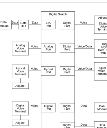
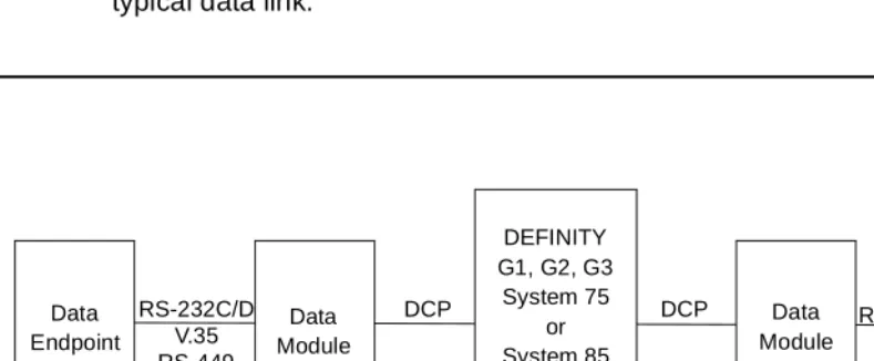
Figure 1-1. Interface Between System Switch and Typical Terminals/Adjuncts
Data Data Module Data Data Module To Private Data Voice/Data Voice Data Terminal Data Unit EIA Port
Data Data Digital
Port Digital Switch Voice Adjunct Digital Voice Terminal Voice/Data Voice Analog Voice Terminal Hybrid Voice Terminal Display/ Keyboard Data Terminal with Voice Digital Voice Terminal Data Module Adjunct Analog Port Digital Port Hybrid Port Digital Port Data Data Terminal Data Voice Digital Voice Terminal Adjunct Digital Port Digital
Port ModuleData TerminalData Data
Digital
Port Line Trunk
Introduction
1-4 The Organization of This Manual
1
The Organization of This Manual
The remainder of this manual is divided into nine main sections; tabs are provided for convenient access to each section. All equipment descriptions are supported by illustrations.
General Information — Gives background data that applies to the entire range of
equipment covered in this manual.
Exposed Port Protection — Contains information on the protection required by
exposed ports. This section also lists some of the Lucent Technologies protection devices and gives parameters that non-Lucent Technologies devices must meet.
Adjunct Power — Lists the different terminals and adjuncts that require adjunct
power supplies and the recommended adjunct power supply. Information has also been provided about the MSP-1 local power supply and, more recently, about the 1151A1 and the 1151A2 with Battery Holdover which has replaced the MSP-1.
Administration — When some of the newer terminals are used with some older
versions of the switches, the administration of the switch does not allow for the use of the new terminals. These new terminals must be administered using the administration procedures of a similar older terminal. This is called aliasing. This section contains the aliasing information and the appropriate caveats.
Voice Terminals — Provides detailed coverage of the main groups of voice
terminals, divided into 13 tabbed subsections. This section contains detailed information on each voice terminal that can be ordered as a component of a DEFINITY switch, System 75, or System 85. It also contains brief descriptions of voice terminals that were previously installed in earlier business communications systems. Before you install the voice terminal or telephone, check each
Introduction
1-5 The Organization of This Manual
1
The 13 tabbed subsections and the voice terminals described in each subsection are listed as follows:
6400 SERIES
Models 6402 and 6402D Models 6408+ and 6408D+ Models 6416D+ and 6416D+M Models 6424D+ and 6424D+M
7100 SERIES
Model 7101A
Models 7102A and 7102 Plus Models 7103A Fixed Feature and
7103A Programmable Model 7104A 7200 SERIES Model 7203H Model 7205H 7300 SERIES Model 7303S Model 7305S 7400 SERIES Model 7401D Model 7401 Plus Model 7402 Plus Model 7403D Model 7404D Model 7405D Model 7406D Model 7406 BIS Model 7406 Plus Model 7407D
Model Enhanced 7407D Model 7407 Plus Model 7410D Model 7410 Plus Model 7434D Model 7444 8400 SERIES Model 8403 Model 8405 Model 8410 Model 8411
Model 8434 and 8434DX
CALLMASTER 602 CALLMASTER CALLMASTER II CALLMASTER III CALLMASTER IV CALLMASTER V CALLMASTER VI 500/2500 SERIES
Model 500 Series Model 2500 Series Model 2500 DMGC Model 2500 YMGK
Models 2500 MMGL and 2500 MMGM Models 2500 YMGL and 2500 YMGM Models 2500 YMGN and 2500 YMGP
6200 SERIES
Model 6210
Models 6218 and 6220
8100 SERIES
Models 8101 and 8102M Models 8102 and 8102M Models 8110 and 8110M
ISDN VOICE TERMINALS
Model 7505 ISDN Model 7506 ISDN Model 7507 ISDN Model 8503T ISDN Model 8510T ISDN Model 8520T ISDN
CORDLESS/WIRELESS TELEPHONES
MDC 9000 Cordless Telephone MDW 9000 Wireless Telephone
MDW 9031DCP Wireless Pocket Phone
OTHER
Voice terminals reusable from other systems: Models 7203H, 7303H,
7305H01B, and 7305H02B Multi-Button Electronic
Introduction
1-6 The Organization of This Manual
1
Adjuncts — Contains information on the devices that can be used with voice
terminals to supplement services and features. This section contains information on the controls, buttons, lights, and functions of a DEFINITY G1, G2, and G3, a DEFINITY ECS, System 75, or System 85 voice terminals and telephone
adjuncts. Adjuncts that are identical in appearance and function, but have different codes, are covered under the same heading. Adjuncts that are basically data modules are covered in the Data Modules section in this manual.
The adjuncts covered in this section are:
Call Coverage Modules Message Waiting Indicator Digital Display Module Speakerphones
Function Key Module Loudspeaker
Expansion Modules Messaging Cartridge Tip/Ring Interface Module Automatic Dialer Headset Adapters
Data Modules — Contains information on the devices that provide data
communications interface. This section contains information on the data modules and other related data equipment used with a DEFINITY G1, G2, and G3, a DEFINITY ECS, System 75, or System 85. These devices provide data interface functions which include modems, protocol converters, and data units.
The data modules covered in this section are:
–7400A Data Module –Modular Processor Data –7400B and 7400B Plus Module (MPDM)
Data Module –Modular Trunk Data
–7400D Data Module Module (MTDM)
–7500B Data Module –3270 Data Module
–8400B Plus Data Module –Asynchronous Data Unit (ADU) –ISDN Asynchronous Data –Multiple Asynchronous Data
Module (ADM) Unit (MADU)
–Digital Terminal Data –DCIU Interface Units
Module (DTDM) –2500-SERIES Data Service Unit –Z702AL1 Data Service Unit –Modems (Data Sets)
–703A Data Service Unit –Local Distribution Service –DEFINITY High Speed Link (HSL) Unit (LDSU)
–Processor Data Module (PDM) –Isolating Data Interface (DI) –Trunk Data Module (TDM) –Protocol Converters
PC Platforms (PC/PBX and PC/ISDN) and Application Software — Contains
information on the different PC/PBX Platforms, the PC/PBX Connection, and E78 Plus®/ISDN.
Blank Templates for Model Design — Includes blank templates of voice
General Information
2-1 Voice Terminals
2
2
General Information
This section provides general information on all of the equipment described in this manual. Information is provided on voice terminals, adjuncts, data modules, and data terminals. Detailed information on these types of equipment can be found behind the tab for each particular type of equipment.
Voice Terminals
The advanced, multi-appearance voice terminals combine the capabilities of both a telephone and a terminal and have a variety of controlling and monitoring functions. While providing basic telephone service (placing and answering calls), voice terminals can also be used to activate the advanced features of the system.
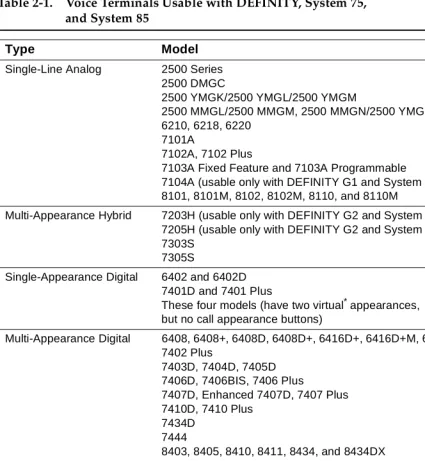
This part explains higher level topics that apply to voice terminals as a group and contains descriptions of facilities and characteristics that are common to all or most terminals. Table 2-1 presents a summary of all voice terminals used with a DEFINITY G1, G2, and G3, a DEFINITY ECS, System 75, and System 85.
General Information
2-2 Voice Terminals
2
Single-Line Voice Terminals
The term “single-line” means that only one incoming call can be ringing at an idle terminal. Once an incoming call has been answered, however, a single-line voice terminal can handle both the active call and another call on hold or waiting. When a single-line terminal user is busy on a call, an incoming call does not ring but alerts the user via a “call waiting tone” (in the handset or speakerphone) that a call
is waiting to be answered. While a single-line terminal is occupied with two calls, any other calls placed to the terminal get a busy tone.
All single-line voice terminals are analog in operation; that is, transmission of all signals between the terminal and its port, at the system digital switch, is in analog form over a tip and ring pair of wires. The port circuit provides analog/digital signal conversion. Power for these terminals is supplied from the switch on the single voice pair. Single-line terminals have many applications but are more limited in their access to system features than multi-appearance terminals.
Multi-Appearance Voice Terminals
A multi-appearance voice terminal gives its user much more flexibility in handling calls than a single-line voice terminal. A multi-appearance voice terminal,
represented by a unique primary extension number, has multiple call appearances (buttons with lights) where incoming calls to the number can be answered and outgoing calls can be originated. Incoming calls can ring simultaneously at all appearances except for those translated as originate-only. As long as at least one appearance is idle, callers will not receive busy tone. When all call appearances, except call appearances translated as originate-only, are busy, callers will hear busy tone unless the incoming call is a priority call or the Restrict Last
Appearance feature is deactivated. The terminal user must decide the order to answer multiple incoming calls.
The two sub-types of multi-appearance voice terminals are digital and hybrid. Digital terminals generate and receive voice and control signals in digital form. Connection between terminals and the system switch is over 2-pair digital links; no conversion is necessary at the digital line port. Hybrid terminals, as the name implies, combine analog and digital. They are connected to the system switch by three pairs of links; on MET*-like hybrid sets, one pair is for analog voice, and the other two pairs are for digital control signals, and on ATL†-like hybrid sets, one pair is for digital control signals, and the other two pairs are for analog voice. DC power for all multi-appearance terminals (except for the 7404D and 7407D01B, which are AC powered) is conducted from the switch over the digital pairs.
Digital multi-appearance voice terminals have several important advantages over hybrids:
* The Multi-Button Electronic Telephone (MET) sets are described in Chapter 19, “Other Voice Terminals.”
General Information
2-3 Voice Terminals
2
■ Digital voice terminals can support and control data terminals. ■ The Digital Communications Protocol (DCP) or ISDN-BRI interface
between a digital voice terminal and the system switch supports
simultaneous voice and data calls over the terminal’s standard mounting cord.
■ Digital terminals have a wider selection of adjuncts.
General Information
2-4 Voice Terminals
2
Table 2-1. Voice Terminals Usable with DEFINITY, System 75,
and System 85
Type Model
Single-Line Analog 2500 Series 2500 DMGC
2500 YMGK/2500 YMGL/2500 YMGM
2500 MMGL/2500 MMGM, 2500 MMGN/2500 YMGP 6210, 6218, 6220
7101A
7102A, 7102 Plus
7103A Fixed Feature and 7103A Programmable 7104A (usable only with DEFINITY G1 and System 75) 8101, 8101M, 8102, 8102M, 8110, and 8110M
Multi-Appearance Hybrid 7203H (usable only with DEFINITY G2 and System 85) 7205H (usable only with DEFINITY G2 and System 85) 7303S
7305S
Single-Appearance Digital 6402 and 6402D 7401D and 7401 Plus
These four models (have two virtual*appearances, but no call appearance buttons)
Multi-Appearance Digital 6408, 6408+, 6408D, 6408D+, 6416D+, 6416D+M, 6424D+, and 6424D+M 7402 Plus
7403D, 7404D, 7405D 7406D, 7406BIS, 7406 Plus
7407D, Enhanced 7407D, 7407 Plus 7410D, 7410 Plus
7434D 7444
8403, 8405, 8410, 8411, 8434, and 8434DX 602A, 602D CALLMASTER
CALLMASTER II with Recorder Interface CALLMASTER III without Recorder Interface CALLMASTER IV
CALLMASTER V CALLMASTER VI
ISDN Terminals 7505, 7506, 7507 (usable only with DEFINITY)
8503T, 8510T, 8520T (usable only with DEFINITY G2 and G3) Cordless and Wireless MDC 9000 Cordless Telephone
MDW 9000 Wireless Telephone
Continued on Next Page
General Information
2-5 Voice Terminals
2
Facilities Common to All Voice Terminals
Every DEFINITY G1, G2, and G3, DEFINITY ECS, System 75, and System 85 voice terminal has the following equipment:
■ A pushbutton pad for touch-tone dialing (except for the Model 500, which
has a rotary dial).
■ A handset with a coiled modular cord.
■ A 7-foot modular mounting cord (except for the Model 2554 wall set).
Buttons
All multi-appearance voice terminals and most single-line terminals have buttons for handling calls and activating various functions that enhance basic calling.
Fixed Feature Buttons
Buttons that are factory labeled and require no administration are referred to as fixed feature buttons. The following buttons, in several combinations, are found on most voice terminals. They are dedicated to standard calling functions and are located adjacent to or above the pushbutton dial pad for calling convenience.
NOTE:
Fixed feature buttons that are limited to a small number of terminals are explained in the detailed descriptions of those terminals.
■ Recall Button (on older sets)—provides a timed flash that is more accurate
than a manual switchhook flash and prevents accidental dropping of calls. The following list of uses for this button is only valid for single-line
terminals:
Type Model
Single-Line Analog 500 (can also be ordered new) 2500 Series (can also be ordered new) Multi-Appearance Hybrid
(MERLIN)
7305H, 7305H01B, and 7305H02B
Multi-Button Electronic Telephone (MET) Sets
10 Button with or without Built-In Speakerphone, 20 Button, 30 Button 7203M (12 button)
* The word “virtual” refers to the fact that there are no call appearance buttons associated with either appearance. Refer to the description of the 7401D and 7401 Plus Voice Terminal for more information.
Table 2-1. Voice Terminals Usable with DEFINITY, System 75,
General Information
2-6 Voice Terminals
2
— Put an active call on hold and obtain recall dial tone for making another call.
— Disconnect from a second call and return to a call on hold, when pressed twice.
— Place an active call on hold and answer a waiting call using Dial Access Code, then toggle between the two calls (using the Recall button and Dial Access Code).
— Place an active call on hold; receive recall dial tone, and dial the Feature Access Code to answer a waiting call. Toggle between the two calls by performing the same action.
— Add a party, previously put on hold, to a conference with a third party.
— Drop the party previously added.
■ Disconnect Button (on older sets)—allows the terminal user, after
completing one call, to permanently disconnect from the call and get dial tone for placing a new call without going on- and off-hook. On System 85 and DEFINITY G2, depending on the administration, this button can be used to reconnect to the call on hold on multiple appearance voice terminals.
■ Hold Button—is used to temporarily disconnect from one call, without
dropping it, so that another call can be answered or originated. The user can return to the call on hold.
■ Drop Button—is used to permanently disconnect the last party added to a
conference call. On System 85 and DEFINITY G2, this button also gives dial tone on the same call appearance if dialing or on a 2-party call.
NOTE:
On some voice terminals, this button is also used to perform a test of the voice terminal’s lights, ringer, and display (if the terminal has one).
■ Conference Button—enables the terminal user to set up a conference call
by adding new calls to an existing 2-party connection. The user can add as many as five calls to a conference. (On System 85 and DEFINITY G2 the user can only build a 3-party conference call using this button; 6-party conference calls can be built by the attendant.)
NOTE:
On some voice terminals, this button is also used to select a personalized ring from eight available ringing patterns.
■ Transfer Button—enables the terminal user to shift an active call to
another voice terminal.
■ Select Ring Button (on older sets)—enables the terminal user to select a
General Information
2-7 Voice Terminals
2
■ Speaker Button—turns on either a listen-only speaker or a 2-way
speakerphone which allows the user to speak and listen to the far-end party.
NOTE:
On some voice terminals, this button also allows the user to initiate an acoustic test of the surrounding environment (the Reset
Speakerphone feature) through a series of tones. When the tones stop, the speakerphone has finished adjusting itself for optimal performance.
■ Mute Button—turns off the microphone of the built-in speakerphone or the
handset so the other person on the call cannot hear you.
Administrable Buttons
Buttons that are not fixed feature buttons are administered (or assigned) by the System Manager or the terminal user for many functions. Buttons that may be administered include call appearance/feature buttons and feature-only buttons.
General Information
2-8 Voice Terminals
2
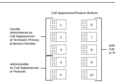
Figure 2-1. Call Appearance/Feature Buttons
Associated with each call appearance/feature button is a pair of lights that provide information on the availability and status of the appearance. These lights are described in the next part of this manual (titled “Lights”).
Any button that can be administered and is not used for a call appearance can be assigned to an optional feature. Included in this category are buttons with two lights (call appearance/feature buttons) and buttons with one or no lights, intended specifically for features. Some features require light feedback to inform the terminal user when the feature is active; others are simple, one-time operations for which light feedback would be meaningless. Good feature administration matches features to appropriate buttons whenever possible.
Lights
Indicator lights provide silent visual reminders to the voice terminal user regarding lines, features, and messages taken at other locations. The lights on voice terminals connected to a DEFINITY G1, G2, and G3, a DEFINITY ECS, System 75, or System 85 are light-emitting diodes (LEDs) or neon lights.
On all multi-appearance voice terminals, each call appearance/feature button has two indicator lights: a red light and a green status light. When a call
appearance/feature button is used for a feature, only the status light is 1
Usually
2
3
4
5 Administered as
Call Appearances of Terminal’s Primary Extension Number
Administrable as Call Appearances or Features
Call Appearance/Feature Buttons
6
7
8
9
10
Administrable as Call Appearances or Features
General Information
2-9 Voice Terminals
2
operational; the red light remains off at all times. Feature-only buttons have either a single green status light or no light at all. The various arrangements of red and green lights are shown in Figure 2-2.
Figure 2-2. Button Lights
Red Light
The red light normally has two states: lighted steadily or dark (off).
NOTE:
On the ISDN-BRI 7505, 7506, and 7507 sets, the red light flashes when the set is using phantom power.
One red light is always on at a multi-appearance voice terminal when the handset is on hook. It identifies the call appearance the user will be automatically
connected to if the handset is lifted. When the handset is lifted, the red light identifies the call appearance that is active.
The red light is off when the handset is lifted but not connected to a call appearance. For example, when one call has been put on hold but another call appearance button has not been pressed. When certain features such as Preselection, Idle Line Originating preference, or No Line Originating Preference are administered, the red light is also off while on hook.
Green Status Light
The green status light can indicate any one of the following six conditions:
■ Off—the call appearance is idle or the assigned feature is not activated.
Red Light
Green Status Light Green Status Light
Green Status Light Red Light
Two Styles of Light Arrangement for Call Appearance/Feature Buttons
Green Status Light
General Information
2-10 Voice Terminals
2
■ Lighted steadily—the call appearance is busy or the assigned feature is
active.
■ Flashing (slow on-off for equal periods, one cycle per second)—an
unanswered incoming call on that call appearance.
■ Fluttering (fast on-off for equal periods, 10 cycles per second)—a call
placed on hold on that call appearance by the voice terminal user.
■ Broken Fluttering (fast on-off modulated at the slow rate)—feature denial to
the calling voice terminal or an unknown or invalid action.
■ Winking (long on-short off at about three cycles per second)—a call placed
on hold from another voice terminal or an action pending.
Message Light
The Message light, when on, indicates that a message is waiting for the voice terminal’s user (for example, Leave Word Calling or voice mail messages). When the user retrieves the message, the light is automatically turned off.
Tones
The tones that a voice terminal user hears can be divided into two categories:
■ Ringing Tones—those that are generated in the base of the voice terminal
and can be heard in the surrounding area; they indicate incoming calls.
■ Handset Tones—those that are transmitted through the handset and heard
only by the user or through the speakerphone when it is turned on.
External Ringing Tones
Ringing tones are the only tones heardoutside the voice terminalwhen it is receiving a call. This signal cycles in 1-, 2-, or 3-ring patterns. On System 75 and DEFINITY G1 and G3, only one cycle of ringing is heard if the multi-appearance voice terminal is busy with another call. On System 85 and DEFINITY G2, the cycling repeats (except on the ISDN 7500-series sets).
■ One ring—a call from another voice terminal in the system ■ Two rings—a call from the attendant or outside caller
■ Three rings—priority calls, for example, Automatic Callback, Priority
Calling, or Ringback from a queued call
■ One short unmodulated tone—an intercom call
■ Ring-Ping (half ring)—a call redirected away from the voice terminal
because Send All Calls or Call Forwarding is active; also called coverage tone.
■ On System 85 and DEFINITY G2, any of these external tones, plus a
General Information
2-11 Voice Terminals
2
Handset Tones
The following tones are heard through the handset:
■ Answer Tone—a high-pitched continuous tone indicating that a data
endpoint has answered.
■ Busy Tone—a low-pitched tone repeated 60 times a minute; indicates that
the number dialed is in use.
■ Call Waiting Tone (Single-Line Voice Terminals)—one, two, or three
beeps (short bursts of high-pitched tone), not repeated; indicates to the user at a busy single-line terminal that an incoming call is waiting to be answered. The number of beeps indicates the source of the waiting call:
— One beep—a call from another voice terminal in the system
— Two fast beeps—a call from the attendant or an outside caller
— Three fast beeps—a priority call
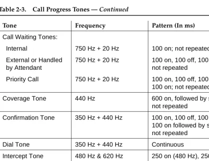
■ Confirmation Tone—(three short bursts of tone) indicates that a feature
activation or cancellation has been accepted, or that an outgoing call from a single-line voice terminal has been placed in a ringback queue.
■ Coverage Tone—(one long burst of tone) indicates to the calling party that
a call to an extension number will be answered at another extension number by a covering user.
■ Dial Tone—(a continuous steady tone) indicates that dialing or feature
activation can begin.
■ Intercept Tone—(an alternating high and low tone) indicates either a
dialing error or a denial of the service requested.
■ Recall Dial Tone—(three short bursts of dial tone followed by steady dial
tone) indicates that the feature requested has been accepted and dialing can start.
■ Recorded Telephone Dictation Ready Tone—(a high-pitched continuous
tone) indicates that a dictation machine has been connected to the voice terminal.
■ Reorder Tone—(a fast-busy tone repeated 120 times a minute) indicates
that all outgoing trunks are busy or feature resource is not available. Try again.
■ Ringback Tone—(a low-pitched tone repeated 15 times a minute)
indicates to the calling party that the number dialed has been reached successfully and is ringing.
■ Ringback Tone, Call Waiting—(a ringback tone with a short lower-pitched
signal at the end) indicates to the calling party that the extension called is busy, but that the called party has been given the call waiting signal.
■ Time-Out Tone— (an alternating high and low tone [same as intercept
General Information
2-12 Adjuncts
2
■ Warning Tone (Bridging)—(a low-pitched tone heard by all parties in a
Busy Verification attempt that bridges on to an active call) initially applied in a 2-second (System 75 and G1) or 4-second (System 85 and G2) burst, then in half-second bursts every 15 seconds.
Desk/Wall Mounting Arrangements
All the voice terminals covered in this manual, except the Model 2554, are intended for free-standing desktop use. However, wall-mounting is feasible for many terminals and appropriate kits are available. The detailed description of each voice terminal contains wall-mounting information and limitations.
Adjuncts
Adjuncts are optional devices that extend the existing capabilities of voice terminals or provide new services. Some adjuncts are physically attached to their voice terminals, and others are free-standing, connected by way of mounting cords. The adjuncts have styling and colors that are compatible with the associated voice terminals.
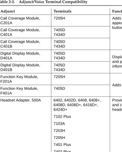
Table 2-2 provides a cross-reference between adjuncts and the voice terminals with which they are used. The following limitations apply to the use of multiple adjuncts:
■ A speakerphone and a headset adapter cannot be connected to the same
voice terminal simultaneously because they plug into the same jack on the terminal.
■ A C401A Call Coverage Module and a D401A Digital Display Module
cannot be mounted on the same 7405D or 7434D Voice Terminal simultaneously because they attach to the same part of the terminal.
General Information
2-13 Adjuncts
2
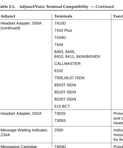
Table 2-2. Adjunct/Voice Terminal Compatibility
Adjunct Terminals Function
Call Coverage Module, C201A
7205H Adds 20 call
appearance/ feature buttons
Call Coverage Module, C401A
7405D 7434D
Call Coverage Module, C401B
7405D 7434D
Digital Display Module, D401A
7405D
7434D Displays call-related
and personal service information
Digital Display Module, D401B
7405D 7434D
Function Key Module, F201A
7205H
Adds 24 feature buttons Function Key Module,
F401A
7405D
Headset Adapter, 500A 6402, 6402D, 6408, 6408+, 6408D, 6408D+, 6416D+, 6424D+ 7102 Plus 7103A 7203H 7205H 7401 Plus 7402 Plus 7403D 7405D 7406D 7406BIS 7406 Plus Enhanced 7407D 7407 Plus
Provides for connection and control of standard headset
General Information
2-14 Adjuncts
2
Headset Adapter, 500A (continued)
7410D
7410 Plus
7434D
7444
8403, 8405,
8410, 8411, 8434/8434DX
CALLMASTER
8102
7505,06,07 ISDN
8503T ISDN
8510T ISDN
8520T ISDN
515 BCT
Headset Adapter, 502A 7303S
7305S
Provides for connection and control of standard headset
Message Waiting Indicator, Z34A
2500 Indicates that a
message has been left for the terminal
Messaging Cartridge 7404D Provides display of call-related and personal service information on data terminal screen
PC/PBX Plug-in Cartridge 7404D Provides interface with PCs
Speakerphone, S101A
Speakerphone, S201A
Same as 500A
Headset Adapter
Provides hands-free calling
Continued on Next Page
Table 2-2. Adjunct/Voice Terminal Compatibility — Continued
General Information
2-15 Data Modules
2
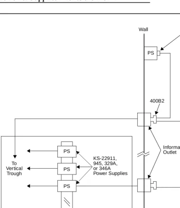
Several power supplies and connection schemes are available for providing auxiliary ad