Release 6.0
Network Reference
555-660-150
Comcode 108136011
Issue 1
Notice
Every effort was made to ensure that the information in this book was complete and accurate at the time of printing. However, information is subject to change. See Appendix A, “Customer Support Information,” for important information.
Your Responsibility for Your System’s Security
Toll fraud is the unauthorized use of your telecommunications system by an unauthorized party, for example, persons other than your company’s employees, agents, subcontractors, or persons working on your company’s behalf. Note that there may be a risk of toll fraud associated with your telecommunications system, and if toll fraud occurs, it can result in substantial additional charges for your telecommunications services. You and your System Manager are responsible for the security of your system, such as programming and configuring your equipment to prevent unauthorized use. The System Manager is also responsible for reading all installation, instruction, and system programming documents provided with this product in order to fully understand the features that can introduce risk of toll fraud and the steps that can be taken to reduce that risk. Lucent Technologies does not warrant that this product is immune from or will prevent unauthorized use of common-carrier telecommunication services or facilities accessed through or connected to it. Lucent Technologies will not be responsible for any charges that result from such unau-thorized use. For important information regarding your system and toll fraud, see Appendix A, “Customer Support Information.”
Federal Communications Commission Statement
This equipment has been tested and found to comply with the limits for a Class A digital device, pursuant to Part 15 of the FCC Rules. These limits are designed to provide reasonable protection against harmful interference when the equipment is operated in a commercial environment. This equipment generates, uses, and can radiate radio frequency energy and, if not installed and used in accordance with the instruction manual, may cause harmful interference to radio communications. Operation of this equipment in a residential area is likely to cause harmful interference, in which case the user will be required to correct the interference at his own expense. For further FCC information, see Appendix A, “Customer Sup-port Information.”
Canadian Department of Communications (DOC) Interference Information
This digital apparatus does not exceed the Class A limits for radio noise emissions set out in the radio interference regulations of the Canadian Department of Communications.
Le Présent Appareil Numérique n’émet pas de bruits radioélectriques dépassant les limites applicables aux appareils numériques de la classe A préscrites dans le règlement sur le brouillage radioélectrique édicté par le ministère des Communications du Canada.
Trademarks
DEFINITY, HackerTracker, MLX-5, MLX-5D, MLX-10, MLX-10D, MLX-10DP, MLX-16DP, MLX-20L, MLX-28D, and PassageWay, are registered trademarks and Lucent Technologies is a trademark of Lucent Technologies in the US and other countries. NetPROTECT is a service mark of Lucent Technologies in the US and other countries.
Novell and NetWare are registered trademarks of Novell, Inc. Ordering Information
For more information about Lucent Technologies documents, refer to the section entitled, “Related Documents”. Support Telephone Number
In the continental US, Lucent Technologies provides a toll-free customer helpline 24 hours a day. Call the Lucent Technologies Helpline at 1 800 628-2888 or your Lucent Technologies authorized dealer if you need assistance when installing, programming, or using your system. Consultation charges may apply. Outside the continental US, contact your local Lucent Technologies authorized representative.
Lucent Technologies Fraud Intervention
If you suspect you are being victimized by toll fraud and you need technical support or assistance, call Lucent Technologies National Customer Care Center at 1 800 628-2888.
Warranty
Lucent Technologies provides a limited warranty on this product. Refer to “Limited Warranty and Limitation of Liability” in Appendix A, “Customer Support Information.”
Call: BCS Publications Center
Voice 1 800 457-1235 International Voice 317-322-6791 Fax 1 800 457-1764 International Fax 317-322-6699
Write: BCS Publications Center 2855 North Franklin Road Indianapolis, IN 46219-1385
Order: Document No. Lucent Technologies 555-660-150 Comcode: 108136011
Contents
Contents iii
Figures ix
Tables xi
New Features and Enhancements xiii
■ Release 6.0 Enhancements xiii
Prior Releases: Features and Enhancements xix
■ Release 3.1 Enhancements xix
■ Release 4.0 Enhancements xxii
■ Release 4.1 Enhancements xxv
■ Release 4.2 Enhancements xxvii
■ Release 5.0 Enhancements xxix
IMPORTANT SAFETY INSTRUCTIONS xxxv
About This Book xxxvii
■ Intended Audience xxxvii
■ How to Use This Book xxxviii
■ Terms and Conventions Used xxxviii
■ Security xl
■ Related Documents xl
■ How to Comment on This Book xli
1
Introduction 1–1■ Networking Concepts 1–1
■ Tandem Trunking and Tandem Switching 1–4
■ Uniform Dial Plan 1–16
2
Call-Handling Scenarios 2–1■ Networking Guidelines 2–2
■ Network Configuration Scenarios 2–12
3
Feature Interactions 3–1■ Account Code Entry 3–1
■ Alarm 3–1
■ Allowed/Disallowed Lists 3–1
■ Auto Answer All 3–2
■ Auto Answer Intercom 3–2
■ Auto Dial 3–2
■ Automatic Route Selection (ARS) 3–3
■ Barge-In 3–4
■ Callback 3–4
■ Caller ID 3–4
■ Calling Restrictions 3–5
■ Camp-On 3–5
■ Computer Telephony Integration
(CTI) Link 3–6
■ Conference 3–7
■ Coverage 3–7
■ Digital Data Calls 3–7
■ Direct-Line Console (DLC) 3–7
■ Direct Station Selector (DSS) 3–7
■ Direct Voice Mail 3–7
■ Directories 3–8
■ Display 3–8
■ Extended Station Status 3–8
■ Forward and Follow Me 3–9
■ Group Calling 3–10
■ Hands Free Answer on Intercom (HFAI) 3–10
■ HotLine 3–10
■ Labeling 3–10
■ Messaging 3–11
■ Music On Hold 3–11
■ Night Service 3–11
■ Paging 3–12
■ Park 3–12
■ Personal Lines 3–12
■ Pickup 3–12
■ Pools 3–12
■ Primary Rate Interface (PRI) and T1 3–13
■ Queued Call Console (QCC) 3–14
■ Remote Access 3–14
■ Signal/Notify 3–15
■ Station Message Detail Recording (SMDR) 3–16
■ Speed Dial 3–16
■ System Renumbering 3–16
■ Transfer 3–17
■ Voice Announce to Busy 3–17
■ Voice Messaging Interface (VMI) 3–18
4
Security 4–1■ Overview 4–2
■ Facility Restriction Levels and Remote Access 4–5
5
System Management 5–1■ General Programming in Networks 5–2
■ Non-Local Dial Plan Numbering 5–10
■ Switch Identifiers 5–13
■ Tandem PRI Facilities 5–16
■ Uniform Dial Plan Routing 5–19
■ Display Preferences for Intersystem Calls 5–25
6
Troubleshooting 6–1■ Troubleshooting Guidelines and Preparation 6–2
■ Call to a Non-Local Extension: Unexpected Busy Tone 6–3
■ Call to Non-Local Extension:
Silence or Fast Busy Tone 6–5
■ Call to Non-Local Extension: Warble Tone (Error Tone) 6–10
■ Calls to Non-Local Extensions:
Unexpected Busy Tone 6–12
■ Call to Non-Local Extension Reaches Wrong Extension 6–13
■ Call to Non-Local Extension: Message from CO 6–14
■ Transfer to Non-Local Extension Not Completed 6–14
■ Transfer Call to Non-Local Extension Does Not Return 6–15
■ Conference: Cannot Add Call 6–15
■ DID Calls Not Completed 6–16
■ ARS Calls Are Blocked 6–17
■ Callback Does Not Work 6–18
■ Network Call Transmission Level (Volume)
■ MLX Displays: Network Call Display Problems 6–20
■ PassageWay Call Display Problems 6–21
■ ARS Calls Go to System
Operator (Unassigned Extension) 6–22
■ DID or PRI Dial-Plan Routed Calls Not Completed 6–23
■ Excessive Line Noise on Voice and Data Calls 6–23
■ Station Message Detail Recording (SMDR) Reports
Do Not Include Calls across the Network 6–24
A
Customer Support Information A–1■ Support Telephone Number A–1
■ Federal Communications Commission (FCC)
Electromagnetic Interference Information A–1
■ Canadian Department of Communications (DOC)
Interference Information A–2
■ FCC Notification and Repair Information A–2
■ Installation and Operational Procedures A–4
■ DOC Notification and Repair Information A–5
■ Renseignements sur la notification du ministère des
Communications du Canada et la réparation A–6
■ Security of Your System: Preventing Toll Fraud A–9
■ Toll Fraud Prevention A–10
■ Other Security Hints A–16
■ Limited Warranty and Limitation of Liability A–21
■ Remote Administration and Maintenance A–22
B
Sample Reports B–1■ Dial Plan Report B–6
■ Non-Local Dial Plan Report B–9
■ Tie Trunk Information Report B–10
■ DID Trunk Information Report B–11
■ General Trunk Information Report B–12
■ DS1 Information Report B–13
■ PRI Information Report B–14
■ Remote Access (DISA) Information Report B–18
■ Disallowed Lists Report B–19
■ Access to Disallowed Lists Report B–19
■ Automatic Route Selection Report B–20
■ Extension Information Report B–22
■ Error Log Report B–24
■ Switch 56 Data Information Report B–25
GL
Glossary GL–1Figures
1
Introduction
1–11–1 Series Configuration 1–5
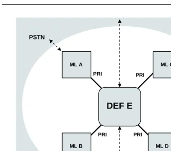
1–2 Star Configuration: Five Systems 1–7
1–3 Star Configuration: Three Systems 1–8
1–4 Series Configuration: Four Systems 1–11
1–5 Star Configuration: Three Systems 1–13
1–6 Star Configuration: Five Systems 1–15
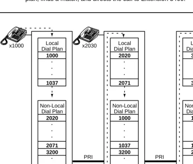
1–7 Uniform Dial Plans 1–17
2
Call-Handling Scenarios
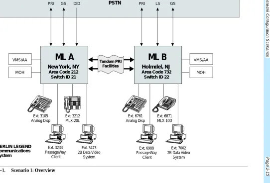
2–12–1 Scenario 1: Overview 2–15
2–2 Scenario 2: Company Floor Plans 2–29
2–3 Scenario 2: Overview 2–40
2–4 Scenario 3: Overview 2–51
2–5 Scenario 4: Overview 2–64
2–6 Scenario 5: Overview 2–77
4
Security
4–1Tables
1
Introduction
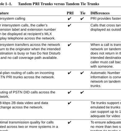
1–11–1 Tandem PRI Trunks versus Tandem Tie Trunks 1–10
2
Call-Handling Scenarios
2–12–1 UDP Extension Ranges: Scenario 1 2–19
2–2 Scenario 1: Facilities Planning, Calls Originating
within the Network and Going to the PSTN 2–20
2–3 Scenario 1: ARS Routing Summary, Calls Originating
within the Network and Going to the PSTN 2–21
2–4 Outside Calls: Scenario 1 2–23
2–5 Intersystem Calling: Scenario 1 2–26
2–6 Work Group Needs 2–31
2–7 Individual Needs 2–33
2–8 UDP Extension Ranges: Scenario 2 2–42
2–9 Scenario 2: Facilities Planning, Calls Originating
within the Network and Going to the PSTN 2–43
2–10 Scenario 2: ARS Routing Summary, Calls Originating
within the Network and Going to the PSTN 2–44
2–11 Outside Calls: Scenario 2 2–46
2–12 Intersystem Calling: Scenario 2 2–49
2–13 UDP Extension Ranges: Scenario 3 2–54
2–14 Scenario 3: Facilities Planning, Calls Originating
within the Network and Going to the PSTN 2–55
2–15 Scenario 3 ARS Routing Summary: Calls Originating within the Network and Going to the PSTN:
Systems J & K 2–56
2–16 Scenario 3 ARS Routing Summary: Calls Originating within the Network and Going to the PSTN:
Systems L & M 2–57
2–17 Outside Calls: Scenario 3 2–59
2–18 Intersystem Calling: Scenario 3 2–62
2–19 UDP Extension Ranges: Scenario 4 2–68
2–20 Scenario 4: Facilities Planning, Calls Originating within the Network and Going to the PSTN,
2–21 Scenario 4: Facilities Planning, Calls Originating within the Network and Going to the PSTN,
Systems F and G 2–71
2–22 Outside Calls: Scenario 4 2–73
2–23 UDP Extension Ranges: Scenario 5 2–80
2–24 Scenario 5: Facilities Planning, Calls Originating
within the Network and Going to the PSTN 2–81
2–25 Outside Calls: Scenario 5 2–83
2–26 Intersystem Calling: Scenario 5 2–85
4
Security
4–14–1 Calling Restrictions and Security Feature Planning in
Networks 4–3
4–2 Recommended Settings for Tie and Non-Tie Default
COR and Callback 4–9
4–3 Facility Restriction Levels 4–11
B
Sample Reports
B–1B–1 Sample Report Pages B–1
New Features and Enhancements
0
Release 6.0 Enhancements
0
Release 6.0 includes all Release 5.0 functionality, plus the enhancements listed below.
Private Networks
0
In Hybrid/PBX mode systems only, MERLIN LEGEND Communications Systems can be networked with one another or with DEFINITY® Enterprise
Communications Server (ECS) and ProLogix™ Communications Systems in private networks. In previous releases, this functionality is available using tie lines, but users handle calls between networked switches as outside calls. In this release, dialing the pool access code is not necessary for a call going from one networked switch to another. Also, delay-start tie trunks or T1 trunks administered as PRI can act as tandem trunks to connect networked systems.
Available for Hybrid/PBX mode systems, the private network features of the MERLIN LEGEND Communications System Release 6.0 provide the following advantages for geographically dispersed organizational sites:
■ Intersystem Calling. In a private network, users on one local system can
trunks to pools. Then he or she programs as many as 20 patterns, associates with routes, Facility Restriction Levels (FRLs), digit absorption, and digit prepending. This allows ARS-like routing of non-local dial plan calls. In addition, system managers can control whether calling name, calling number, or both are shown at MLX display telephone for incoming calls across PRI tandem trunks.
■ Toll Savings. Private networked trunks may allow you to realize significant
cost savings on long-distance and toll calls by performing tandem switching in the following two ways:
— Callers on a local system, or individuals dialing in to remote access at a local system, can reach the public switched telephone network (PSTN) via outside trunks connected to other systems in a private network, avoiding toll charges or decreasing the cost of toll calls. No special dialing is required. For example, an organization might have a main office in Boston and a subsidiary office in New Jersey, connected by networked private tandem trunks between two systems. A user in the New Jersey office who wishes to make an outside call to the 617 area code (Boston) can do so through a line/trunk connected to the system in Boston. For example, he or she might dial, . The local ARS tables would route this call over the private network trunks and use the ARS tables of the remote system in Boston to route this call. The system managers at each end of a private network set up ARS and Remote Access features to implement this functionality.
— In addition, local organizations or incoming DID calls use private networked trunks to make intersystem calls between networked systems, which may be geographically distant from one another, also resulting in toll savings.
■ Service Cost Savings. In addition to toll call saving, there are two ways
that organizations can save on service costs incurred from
telecommunications providers that provide public switched telephone network access:
— You order a point to point T1 facility from a service provider, then use system programming to set it up for PRI signalling. As necessary, a service provider can provide amplification on the T1 facility, but does not supply switching services.
— You can tailor use of T1 channels to support both T1-emulated tandem tie service and T1 Switched 56 service for data
communications at 56 kbps per channel, allowing 2B data transfers at 112 kbps. You can also use drop-and-insert equipment to provide fractional T1 use.
■ Voice Mail and Auto Attendant. Networked systems should have their
own local voice mail and/or auto attendant applications as well as their own external alerts and Music On Hold sources. However, a single auto attendant can transfer calls throughout the network. It can answer only those calls that arrive on the PSTN facilities of the system where it is connected.
Although many features are available using tie trunks for network connectivity, PRI tandem trunks provide greatly enhanced features and faster call setup. For this reason, PRI is recommended over tie functionality in private networks.
Group Calling Enhancements
0
Release 6.0 and later systems include Group Calling features that enhance group calling operations.
Queue Control
0
The system manager can control the maximum number of calls allowed in the primary calling group queue for calls that arrive on certain facilities often assigned to calling groups. When the number of the calls in queue reaches the
programmed maximum, subsequent callers receive a busy signal.
Queue control applies to calls received on the following types of facilities:
■ DID (Direct Inward Dialing)
■ PRI facilities programmed for dial-plan routing
■ All calls transferred from a VMI (voice messaging interface) port
■ Dial-in Tie
Queue control also applies to internal calls to a DGC group and calls to a calling group through the QCC.
Internal calls that dial or and are directed to a calling group
Remote-access calls to a calling group, coverage calls directed to a calling group, calls directed to calling group through QCC Position-Busy backup, and all other outside calls are not eligible for queue control.
Prompt-Based Overflow
0
System managers can activate the Prompt-Based Overflow option. This option allows callers waiting in queue and listening to a delay announcement to press the # key in order to reach the overflow receiver for the group, which may be the QCC queue or another calling group (including a calling group assigned for a voice mail system).
All three overflow distribution options—based on the number of calls, the time a caller has waited, and according to the caller’s prompt—may be used at one time. In this case, time-based and number-of-calls based options take precedence over overflow distribution based on the caller’s prompt.
When prompt-based overflow distribution is used, an extra TTR must be provided for each delay announcement device assigned to the associated calling group. The delay announcement informs the caller of the # key option to exit the queue and leave rather than waiting for an agent. If no TTR is available when a calling group call arrives, the call is not sent to a delay announcement extension.
Centrex Transfer via Remote Call Forwarding
0
Centrex Transfer via Remote Call Forwarding can be used in all system modes of operation to send outside calls to a remote telephone number or another Centrex station. In this context, the term outside calls refers to calls from outside the communications system, which may originate at extensions in the Centrex system but not connected to the local MERLIN LEGEND Communications System.
An outside call that uses this feature is defined as a call that arrives on an analog Centrex loop-start line at the MERLIN LEGEND Communications System. It may arrive directly or be transferred without consultation or without transfer supervision (in the case of an automated attendant). The forwarding call to the outside number is made on the same line/trunk on which the call arrived, conserving system facilities. The following considerations and rules apply:
■ Only outside Centrex calls are forwarded using this feature.
■ The system must be equipped with analog loop-start Centrex lines and all
loop-start lines in the system must be Centrex facilities. Loop-start lines do not have to provide reliable disconnect for use by the Centrex Transfer via Remote Call Forwarding feature.
Activating Centrex Transfer via Remote Call Forwarding is just like activating regular Remote Call Forwarding and requires that Remote Call Forwarding be enabled for the extension. However, the user dials instead of a dial-out code, and a Pause character may be required after the . The Centrex service provider determines whether the Pause is needed.
Pause cannot be originated from a single-line telephone or a remote access user. A multiline telephone user in the local system must enter an authorization code to activate the feature.
A remote access user may activate the feature without using an authorization code. Barrier code requirements do apply, however.
Authorization Codes and
Remote Call Forwarding
0
In Release 6.0 and later Key or Hybrid/PBX mode systems, forwarding features, including Centrex Transfer via Remote Call Forwarding, but excluding Follow Me, can be activated or deactivated at a multiline telephone by entering the
Prior Releases: Features and
Enhancements
0
Release 3.1 Enhancements
0
Release 3.1 includes all Release 3.0 functionality, plus the enhancements listed below.
Call Restriction Checking for Star Codes
0
Beginning with Release 3.1, a system manager can add star (*) codes to Allowed and Disallowed Lists to help prevent toll fraud. Star codes, typically dialed before an outgoing call, enable telephone users to obtain special services provided by the central office (CO). For example, in many areas, a telephone user can dial *67 before a telephone number to disable central office-supplied caller identification at the receiving party’s telephone. You must contract with your telephone service provider to have these codes activated.
When users dial star codes, the system’s calling restrictions determine whether the codes are allowed. If they are allowed, the system’s calling restrictions are reset and the remaining digits that the users dial are checked against the calling restrictions.
Trunk-to-Trunk Transfer Set for Each Extension
0
Programmable Second Dial Tone Timer
0
The system manager can assign a second dial tone timer to lines/trunks, in order to help prevent toll fraud (for example, when star codes are used). After receiving certain digits dialed by a user, the CO may provide a second dial tone, prompting the user to enter more digits. If this second dial tone is delayed, and the user dials digits before the CO provides the second dial tone, there is a risk of toll fraud or misrouting the call. The second dial tone timer enables the system manager to make sure that the CO is ready to receive more digits from the caller.
Security Enhancements
0
The sections below outside security measures that are implemented in Release 3.1 and later systems.
Disallowed List Including Numbers Often
Associated with Toll Fraud
0
A factory-set Disallowed List 7 contains default entries, which are numbers frequently associated with toll fraud. By default, Disallowed List 7 is automatically assigned to both generic and integrated VMI (voice messaging interface) ports used by voice messaging systems. The system manager can manually assign this list to other extensions.
Default Pool Dial-Out Code
Restriction for All Extensions
0
The default setting for the pool dial-out code restriction (Hybrid/PBX mode only) is restricted. No extension or remote access user with a barrier code has access to pools until the restriction is removed by the system manager.
Default Outward Restrictions for VMI Ports
0
Ports assigned for use by voice messaging systems (generic or integrated VMI ports) are now assigned outward restrictions by default. If a voice messaging system must be allowed to call out (for example, to send calls to a user’s home office), the system manager must remove these restrictions.
SECURITY
l
ALERT:
!
Default Facility Restriction
Level (FRL) for VMI Ports
0
The default Automatic Route Selection (ARS) FRL for VMI ports is 0, restricting all outcalling.
Default for the Default Local Table
0
The default Automatic Route Selection (ARS, Hybrid/PBX mode only) FRL has changed to 2 for the Default Local table. System managers can easily change an extension default of 3 to 2 or lower in order to restrict calling. No adjustment to the route FRL is required.
New Maintenance Procedure for
Testing Outgoing Trunks
0
Technicians must enter a password in order to perform trunk tests.
SECURITY
l
ALERT:
!
Release 4.0 Enhancements
0
Release 4.0 includes all Release 3.1 functionality, plus the enhancements listed below.
Support for Up to 200 Extensions
0
An expanded dial plan supports up to 200 tip/ring devices.
Support for National ISDN BRI Service
0
This service (Hybrid/PBX and Key modes) provides an alternative to loop-start and ground-start lines/trunks for voice and digital data connectivity to the central office. Each of the two B-channels (bearer channels) on a BRI line can carry one voice and one data call at any given time. The data speeds on a B-channel are up to 28.8 kbps for analog data and up to 64 kbps for digital data, which is necessary for videoconferencing and other high-speed applications. Release 4.0 supports the IOC Package “S” (basic call handling) service configuration and Multiline Hunt service configuration on designated CO switches.
New Control Unit Modules
0
Release 4.0 supports a new NI-BRI line/trunk module and a higher-capacity tip/ring module.
800 NI-BRI Module
0
This new module connects NI-BRI trunks to the MERLIN LEGEND system for voice, high-speed data, and video transmission.
016 Tip/Ring Module
0
This new module supports a 200-extension dial plan by providing 16 ports for tip/ring devices. Applications that use a tip/ring interface can connect to this board. All 16 ports can ring simultaneously. Four touch-tone receivers (TTRs) are included on the module as well. The module’s ringing frequency (default 20 Hz) can be changed through programming to 25 Hz for those locations that require it.
Downloadable Firmware for the
016 and NI-BRI Modules
0
Support for 2B Data Applications
0
A Lucent Technologies-certified group and desktop video application can use two B-channels to make video/data calls when connected to a single MLX extension jack programmed for 2B data. The 2B data devices must be equipped with ISDN-BRI interfaces. NI-1 BRI, PRI, or T1 Switched 56 facilities support 2B data communications at 112 kbps (using two 56-kpbs channels) or 128 kbps (using two 64-kbps B-channels). This feature is available for Hybrid/PBX and Key modes only.
Support for T1 Switched 56
Digital Data Transmission
0
For Hybrid/PBX and Key mode systems, Release 4.0 expands support of T1 functionality by providing access to digital data over the public switched 56-kbps network, as well as to digital data tie-trunk services. Users who have T1 facilities for voice services can now use them for video or data calls at rates of 56 kbps per channel (112 kbps for video calls using 2B data). The Release 4.0 offering also includes point-to-point connectivity over T1 tie trunks, allowing customers to connect two MERLIN LEGEND Communications Systems or a MERLIN LEGEND Communications System with a Lucent Technologies DEFINITY® G1.1
Communications System or DEFINITY Enterprise Communications Server. The two communications systems can be co-located or at different sites.
Forwarding Delay Option
0
Each user can program a Forwarding Delay setting for the Forward, Remote Call Forwarding, or Follow Me features. The forwarding delay is the number of times that a call rings at the forwarding extension before the call is sent to the receiver. The delay period gives the original call recipient time to answer or to screen calls by checking the displayed calling number (if available). The delay can be set at 0 up to 9 rings. The factory setting for the forwarding delay is 0 rings (no delay).
Voice Announce on Queued Call Console
0
Time-Based Option for
Overflow on Calling Group
0
Release 4.0 has added a time limit for calls in queue in addition to the previous
number of calls limit. If the Overflow Threshold Time option is set to a valid number between 1 and 900 seconds, calls that remain in the calling group queue for the set time are sent to the overflow receiver. If the overflow threshold time is set to 0, overflow by time is turned off. The factory-set time limit is 0 seconds (off).
Single-Line Telephone Enhancements
0
The following changes enhance the performance of single-line telephones:
■ Disable Transfer. Through centralized telephone programming, the
system manager can disable transfer by removing all but one SA or ICOM button from the extension.
■ No Transfer Return. When a handset bounces in its cradle, the system
interprets this as a switchhook flash and attempts to transfer a call. When the transfer attempt period expires, the user’s telephone rings. Release 4.0 eliminates this unintended ringing by disconnecting the call in situations where a switchhook flash is followed by an on-hook state and a dial tone is present.
■ Forward Disconnect. All ports on 008 OPT, 012, and 016 modules now
send forward disconnect to all devices connected to them when forward disconnect is received from the CO. This enhancement prevents the trunk/line from being kept active when one end disconnects from the call. If an answering machine is connected to the port, it does not record silence, busy tones, or other useless messages. This operation is not
programmable.
Seven-Digit Password for SPM
0
Release 4.1 Enhancements
0
Release 4.1 includes all Release 4.0 functionality, plus the enhancements listed below. There are no hardware changes in Release 4.1.
Coverage Timers Programmed for
Individual Extensions
0
Beginning with Release 4.1, coverage timers, which control the duration of the delay before calls are sent to each level of coverage, are changed as follows:
■ The Group Coverage Ring Delay (1–9 rings) is programmed on individual
extensions and replaces the Coverage Delay Interval programmed systemwide in previous releases.
■ The Primary Cover Ring Delay (1–6 rings) and Secondary Cover Ring
Delay (1–6 rings), programmed on individual extensions, replace the Delay Ring Interval programmed systemwide in previous releases.
These enhancements allow the system manager to customize coverage call delivery to match individual extensions’ call-handling requirements.
Night Service with Coverage Control
0
Beginning with Release 4.1, a system manager can enable the Night Service Coverage Control option to automatically control the status of telephones programmed with Coverage VMS (voice messaging system) Off buttons, according to Night Service status.
When Coverage Control is enabled and the MERLIN LEGEND Communications System is put into Night Service, all programmed Coverage VMS Off buttons are automatically turned off (LED is unlit) and all eligible outside calls are sent to the assigned voice messaging system calling group with normal ringing delay. When Night Service is deactivated during the day, all programmed Coverage VMS Off buttons are automatically turned on (LED is lit) and voice mail coverage is disabled for outside calls.
Users can override the Coverage VMS Off button status at any time by pressing the programmed Coverage VMS Off button to turn the LED on or off.
Night Service Group Line Assignment
0
With this enhancement, Night Service can be activated and deactivated on lines that do not appear on operator consoles (for example, personal lines), and lines appearing at operator positions can be excluded from Night Service.
Forward on Busy
0
Beginning with Release 4.1, the Forward, Follow Me, and Remote Call Forward features are enhanced to remove the requirement that a call be ringing at an extension before it can be forwarded. With the Forward on Busy enhancement, a call to an extension with no available SA (System Access) or ICOM (Intercom) buttons is forwarded immediately to the programmed destination, preventing the caller from hearing a busy signal from the intended call recipient’s extension.
Maintenance Testing for BRI Facilities that Are
Part of Multiline Hunt Groups (MLHGs)
0
Beginning with Release 4.1, the NI-1 BRI (National Integrated Services Digital Network-1 Basic Rate Interface) Provisioning Test Tool is enhanced to include testing for BRI facilities that are part of Multiline Hunt Groups (MLHGs).
Release 4.2 Enhancements
0
Release 4.2 includes all Release 4.1 functionality, plus the enhancements listed below. There are no hardware changes for Release 4.2.
Additional Network Switch and Services Options
for ISDN Primary Rate Interface (PRI)
0
Release 4.2 of the system supports connectivity to MCI® or local exchange carrier (LEC) PRI services and to the following central office switch types (in addition to the 4ESS™ and 5ESS® switch types that carry for AT&T Switched Network services):
■ NORTEL® DMS™-100 BCS 36 for local exchange carrier services
■ NORTEL DMS-250 generic MCI07 serving the MCI network
■ Digital Switch Corporation DEX600E generic 500-39.30 serving the MCI
network
Beginning with Release 4.2, the following MCI PRI and PRI local exchange carrier (LEC) services (along with AT&T Switched Network Services) can be provided to users of the MERLIN LEGEND Communications System:
■ MCI Toll Services for DMS-250 or DEX600E switch type:
— MCI Prism® service for domestic outgoing long-distance and international voice calls; for domestic outgoing 56-kbps restricted, 64-kbps unrestricted, and 64-kbps restricted circuit-switched data calls
— MCI VNet® service for incoming and outgoing domestic and voice calls; for 56-kbps restricted, 64-kbps restricted, and 64-kbps unrestricted circuit-switched data calls
— MCI 800 for domestic, toll-free, incoming voice calls
— MCI 900 service numbers
■ LEC services for DMS-100 switch types:
— DMS Virtual Private Network service for calls between the MERLIN LEGEND Communications System and another communications system (such as another MERLIN LEGEND Communications System)
— DMS INWATS (Inward Wide Area Telephone Service) for domestic toll-free incoming voice calls
— DMS OUTWATS (Outward Wide Area Telephone Service) for domestic outgoing long-distance voice calls
— DMS tie trunk service to provide private exchange call rating for calls placed on a dedicated central office facility between the MERLIN LEGEND Communications System and another communications system (such as another MERLIN LEGEND Communications System)
Improvements to Station Message Detail
Recording (SMDR) and Support for MERLIN
LEGEND Reporter Application
0
The SMDR feature is enhanced to provide more details about calling group agent activities and to help system managers assess the effectiveness of call centers in terms of both agent performance and the adequacy of facilities to handle inbound calls. These improvements apply to calling groups that are programmed as Auto Login or Auto Logout type. The SMDR and MERLIN LEGEND Reporter features listed are administrable:
■ TALK Field. For Auto Login and Auto Logout calling groups, the TALK field
records the amount of time a calling group agent spends on a call.
■ DUR. (DURATION) Field. For Auto Login and Auto Logout calling groups,
call timing begins when a call arrives at MERLIN LEGEND
Communications System and not after a preset number of seconds. Call timing ends when the call is disconnected; either the caller or the agent hangs up. This allows the system manager to determine how long a caller waited for an agent’s attention.
■ Coding of Calls on Reports. An asterisk (*) appears in the call record
when:
a. A call is not answered by an Auto Login or Auto Logout calling group agent and is abandoned while waiting for an agent.
b. The call is answered by someone not a member of an Auto Login or Auto Logout calling group.
An exclamation point (!) signals that an Auto Login or Auto Logout agent handled a call that was answered by someone who was not a member of that Auto Login or Auto Logout with Overflow group. An ampersand (&) in the call record indicates that the group’s overflow receiver answered the call.
MERLIN LEGEND Reporter
0
MERLIN LEGEND Reporter. The default is Off, in which case the Release 4.0 SMDR reports are available. If the option is set to On, the following new reports are provided:
■ Organization Detail Report
■ Organization Summary and Trends Report
■ Selection Detail Report
■ Account Code Report
■ Traffic Report
■ Extension Summary Report
■ Data Report
■ Talk and Queue Time Distribution Report
■ Time of Day Report
■ ICLID Call Distribution Report
■ Facility Grade of Service Report
Maintenance Enhancements
0
Change to Permanent Error Alarm
0
Beginning with Release 4.2, the most recent permanent error alarm is not shown on the System Error Log menu screen but is available as an option from that screen. For details, refer to the Maintenance section of the technician guide,
Installation, Programming, and Maintenance.
Enhanced Extension Information Report
0
Beginning with Release 4.2, the Extension Information Report includes the Extension Status (ESS) and supervisory mode of each extension.
Release 5.0 Enhancements
0
Release 5.0 includes all Release 4.2 functionality, plus the enhancements listed below.
Computer Telephony Integration (CTI)
0
control and monitor MLX and analog multiline telephone (BIS only) operations. The physical connection for the CTI link is an MLX port on a 008 MLX or 408 MLX module on the MERLIN LEGEND Communications System control unit and ISDN link interface card plugged into the customer’s server. The feature is available for Hybrid/PBX mode systems only.
NOTE:
The NetWare server software version must be 3.12, 4.1 or 4.11.
The 008 MLX and 408 MLX modules must have firmware vintage other than 29. If the module has firmware 29, programming a CTI link on the module is prevented. An earlier or later vintage firmware is supported.
Basic Call Control
0
A CTI link application on a user’s computer can assume basic call control of the user’s analog multiline or MLX telephone’s SA buttons. Basic call control includes:
■ Answering calls arriving on an SA button
■ Making calls from an SA button
■ Hanging up calls
■ Hold and retrieving a call on hold at the user’s extension
NOTE:
Transfer and 3-way conference, when handled through a CTI link application, provide the original caller’s calling number information or other information to the transfer receiver or new conference
participant, if the user has screen-pop capability.
Screen Pop
0
Screen pop occurs when the calling number, called number, or other user-defined identifier (such as account code that a voice-response unit prompts the caller to dial) is used to display a screen associated with the far-end party. For example, Caller ID services can be used to support screen pop on a system that includes a CTI link; using the calling party number as a database key code, information about a caller automatically appears on the user’s computer screen when the call arrives at the extension. Depending on the application, screen pop may be available for calls that arrive on line buttons other than SA buttons and/or calls that are answered manually at the telephone rather than by the application.
Screen pop can occur on incoming calls from the following sources:
■ Calling group distribution
■ An extension on the MERLIN LEGEND Communications System
■ Remote access
NOTE:
In the case of remote access calls, the only information that the application can collect about the caller is the remote telephone number.
■ A transfer of a call that was answered by a voice response unit
■ A transfer, redirection, or conference of a call that was answered at a DLC or at a QCC
NOTES:
1. DLCs (Direct-Line Consoles) may use CTI applications. If they do, they perform the same way as other extensions. A DLC assigned to use a CTI link application is a monitored DLC. When a DLC is used as a regular operator console and not using a CTI link extension, it is non-monitored.
2. Calls to a QCC or non-monitored DLC do not initiate screen pop at the operator position, but when an operator directs a call to an extension using a CTI application, caller information does initiate screen pop. If the DLC is non-monitored, screen pops can occur after the DLC releases the call.
3. Calls transferred from Cover buttons on non-monitored DLCs do not initiate screen pop at the destination extension.
HotLine Feature
0
The Release 5.0 HotLine feature is designed for retail sales, catalogue sales, and other types of businesses and organizations and is available in all three modes of system operation. It allows a system manager to program a single-line telephone extension connected to an 008 OPT, 012, or 016 module as a HotLine. When a user lifts the handset at the HotLine extension, the telephone automatically dials the inside extension or outside telephone number programmed as the first Personal Speed Dial number (code #01) for the extension. The system does not permit calls to be transferred, put on hold, or conferenced. (A user can press the telephone’s Hold button, if it has one, to put a call on local hold, but the call cannot be redirected in any way. Switchhook flashes are ignored.)
changes to it or any other extension programming must be performed using centralized telephone programming.
Any type of inside or outside line that is normally available to a single-line telephone can be assigned to a HotLine extension. Generally, the HotLine telephone does not receive calls, and its lines should be set to No Ring.
SECURITY
l
ALERT:
!
If a HotLine extension accesses a loop-start line, that line should provide reliable disconnect and be programmed for reliable disconnect. Otherwise, a user at the extension may be able to stay on the line after a call is completed and then make a toll call.
Group Calling Enhancements
0
Release 5.0 and later systems include Group Calling features that enhance group calling operations.
Most Idle Hunt Type
0
In addition to the Circular (factory setting) and Linear hunt types supported in earlier releases, a third hunt type distributes calling group calls in an order based on which agent has waited the longest since transferring or hanging up on an incoming calling group call. For some applications, this hunt type is more efficient than the circular type because it takes into account the varying duration of calls. The system distributes calls based on when an agent last completed a call, not on when he or she last received one. This hunting method ignores non-calling group calls. For example, if an agent transfers a call that arrived on a line not assigned to the calling group, the calling group member’s most-idle status is unaffected.
Delay Announcement Devices
0
The system manager can designate as many as ten primary delay announcement devices per group rather than the single device for each group that is available in Release 4.2 and earlier systems. Furthermore, an additional secondary delay announcement device can be specified, for a total of ten primary device extensions and one secondary device extension per group.
between repetitions of the secondary announcement if it is set to repeat. (See Group Calling Options in Chapter 4 for guidelines on setting the delay.)
The primary and secondary announcement options, when used together, allow an initial message to play for callers, followed by a repeating announcement that, for example, urges callers to stay on the line and wait for a calling group member.
Two or more groups may share an announcement device.
A primary delay announcement device can be administered as a secondary delay announcement device.
Enhanced Calls-in-Queue Alarm Thresholds
0
Three Calls-in-Queue Alarm thresholds can be set to more clearly indicate the real-time status of the calls waiting in the queue according to the behavior of programmed Queue Alarm buttons. In earlier releases, only one Calls-in-Queue Alarm Threshold setting is available to activate the LEDs at programmed Calls-in-Queue Alarm buttons for a calling group.
Using all three levels, the system manager sets Threshold 3 to the highest value, Threshold 2 to a middle value, and Threshold 1 to the lowest value. A
Calls-in-Queue Alarm button indicates the severity of the alarm conditions in the following ways:
■ If the number of waiting calls is less than the value programmed for Threshold 1 or drops below that level, the LED is unlit.
■ If the number of waiting calls is greater than or equal to the Threshold 1 value but less than the Threshold 2 value, the LED flashes.
■ If the number of waiting calls is greater than or equal to the Threshold 2 value but less than the value for Threshold 3, the LED winks.
■ If the number of waiting calls is greater than or equal to the highest value, Threshold 3, the LED lights steadily.
NOTE:
A DSS (Direct Station Selector) button that is used as a
Calls-in-Queue Alarm button can only indicate two threshold levels, either by flashing or by lighting steadily. If a calling group must use this type of Calls-in-Queue Alarm button, only two threshold levels should be programmed.
An external alert only signals when the number of calls in the queue meets or exceeds the programmed Threshold 3 value.
MLX-5 and MLX-5D Telephones
0
The MLX-5 nondisplay and MLX-5D display telephones are compatible with all system releases. The display telephone includes a 2-line by 24-character display, and both telephones come with 5 line buttons. In systems prior to Release 5.0, the MLX-5 and MLX-5D telephones are treated as MLX-10 and MLX-10D telephones respectively. As of Release 5.0, the system recognizes the MLX-5 and MLX-5D telephones as 5-button telephones.
IMPORTANT SAFETY INSTRUCTIONS
0
When installing telephone equipment, always follow basic safety precautions to reduce the risk of fire, electrical shock, and injury to persons, including:
■ Read and understand all instructions.
■ Follow all warnings and instructions marked on or packed with the product.
■ Never install telephone wiring during a lightning storm.
■ Never install a telephone jack in a wet location unless the jack is specifically designed for wet locations.
■ Never touch uninsulated telephone wires or terminals unless the telephone wiring has been disconnected at the network interface.
■ Use caution when installing or modifying telephone lines.
■ Use only Lucent Technologies-manufactured MERLIN LEGEND
Communications System circuit modules, carrier assemblies, and power units in the MERLIN LEGEND Communications System control unit.
■ Use only Lucent Technologies-recommended/approved MERLIN LEGEND Communications System accessories.
■ If equipment connected to the analog extension modules (008, 408, 408 GS/LS) or to the MLX telephone modules (008 MLX, 408 GS/LS-MLX) is to be used for in-range out-of-building (IROB) applications, IROB protectors are required.
■ Do not install this product near water, for example, in a wet basement location.
■ Do not overload wall outlets, as this can result in the risk of fire or electrical shock.
■ The MERLIN LEGEND Communications System is equipped with a 3-wire grounding-type plug with a third (grounding) pin. This plug will fit only into a grounding-type power outlet. This is a safety feature. If you are unable to insert the plug into the outlet, contact an electrician to replace the obsolete outlet. Do not defeat the safety purpose of the grounding plug.
■ The MERLIN LEGEND Communications System requires a supplementary ground.
■ Do not attach the power supply cord to building surfaces. Do not allow anything to rest on the power cord. Do not locate this product where the cord will be abused by persons walking on it.
■ Slots and openings in the module housings are provided for ventilation. To protect this equipment from overheating, do not block these openings.
■ Never push objects of any kind into this product through module openings or expansion slots, as they may touch dangerous voltage points or short out parts, which could result in a risk of fire or electrical shock. Never spill liquid of any kind on this product.
■ Unplug the product from the wall outlet before cleaning. Use a damp cloth for cleaning. Do not use cleaners or aerosol cleaners.
■ Auxiliary equipment includes answering machines, alerts, modems, and fax machines. To connect one of these devices, you must first have a Multi-Function Module (MFM).
■ Do not operate telephones if chemical gas leakage is suspected in the area. Use telephones located in some other safe area to report the trouble.
WARNING:
!
■ For your personal safety, DO NOT install an MFM yourself.
■ ONLY an authorized technician or dealer representative shall install, set options, or repair an MFM.
■ To eliminate the risk of personal injury due to electrical shock, DO NOT attempt to install or remove an MFM from your MLX telephone. Opening or removing the module cover of your telephone may expose you to dangerous voltages.
About This Book
The MERLIN LEGEND Communications System is an advanced digital switching system that integrates voice and data communications features. This guide provides information about the networking capabilities of MERLIN LEGEND Communications System Release 6.0 (Hybrid/PBX mode), including tandem trunking, tandem switching, and related private network features.
Intended Audience
0
This book is specifically designed to help you fulfill your role as system manager of the MERLIN LEGENDCommunications System Release 6.0. It is designed to help system managers understand the concepts behind these private networks so that you can plan and maintain networked systems. If you have little or no knowledge of the system, you should consult other system documents before attempting to work with private networks. See “Related Documents” on page –xl
for a list of these guides.
How to Use This Book
0
This guide includes five chapters:
■ Chapter 1, Introduction. This chapter provides a grounding in the basic
terminology and concepts that you must understand in order to manage a networked system.
■ Chapter 2, Call-Handling Scenarios. Studies several sample network
configurations, demonstrating how the systems are set up for networking, how calls are made and received, and the advantages and disadvantages of each configuration.
■ Chapter 3, Feature Interactions. Describes the ways that system features
work in networks.
■ Chapter 4, Security. Discusses security issues and considerations.
■ Chapter 6, System Management. Summarizes programming procedures
for setting up and modifying network operations.
■ Chapter 6, Troubleshooting. Describes common problems that you may
encounter, their possible causes, and their solutions.
This guide is intended as a companion to the Release 6.0 Feature Reference,
System Programming, and System Manager’s Guide, which explain many system features and procedures in greater detail. Because private networks leverage existing communications system features as well as introducing new ones, this guide focuses not on a thorough discussion of system management and system features but rather on how they apply to private networks. “Related Documents”
on page –xl provides a complete list of system documentation together with
ordering information.
In the USA only, Lucent Technologies provides a toll-free customer Helpline
24 hours a day. Call the Helpline at 1 800 628-2888 (consultation charges may apply), or call your Lucent Technologies representative, if you need assistance when installing, programming, or using your system.
Terms and Conventions Used
0
The terms described here are used in preference to other, equally acceptable terms for describing communications systems.
Lines, Trunks, and Facilities
Facility is a general term that designates a communications path between a telephone system and the telephone company central office. Technically, a trunk
connects a switch to a switch, for example, the MERLIN LEGEND
intercom line or a Centrex line. However, in actual usage, the terms line and trunk
are often applied interchangeably. In this guide, we use lines/trunks and line/trunk
to refer to facilities in general. Specifically, we refer to digital facilities. We also use specific terms such as personal line, ground-start trunk, DID trunk, and so on. When you talk to your local telephone company central office, ask about the terms they use for the specific facilities they connect to your system.
Typographical Conventions
0
Certain type fonts and styles act as visual cues to help you rapidly understand the information presented:
Product Safety Labels
0
Throughout these documents, hazardous situations are indicated by an exclamation point inside a triangle and the word CAUTION or WARNING.
WARNING:
!
Warning indicates the presence of a hazard that could cause death or severe personal injury if the hazard is not avoided.
CAUTION:
!
Caution indicates the presence of a hazard that could cause minor personal injury or property damage if the hazard is not avoided.
Example Purpose
It is very important that you follow these steps. You must attach the wristband before touching the connection.
Italics indicate emphasis.
The part of the headset that fits over one or both ears is called a headpiece.
Italics also set off special terms.
If you press the Feature button on an MLX display telephone, the display lists telephone features you can select. A programmed Auto Dial button gives you instant access to an inside or outside number.
The names of fixed-feature, factory-imprinted buttons appear in bold. The names of programmed buttons are printed as regular text.
Choose ([W3URJfrom the display screen.
Plain constant-width type indicates text that appears on the telephone display or PC screen.
Security
0
Certain features of the system can be protected by passwords to prevent unauthorized users from abusing the system. You should assign passwords wherever you can and limit knowledge of such passwords to three or fewer people.
Nondisplaying authorization codes and marked System Speed Dial numbers provide another layer of security. For more information, see Appendix A, “Customer Support Information.”
Throughout this document, toll fraud security hazards are indicated by an exclamation point inside a triangle and the words SECURITY ALERT.
SECURITY
l
ALERT:
!
Security Alert indicates the presence of a toll-fraud security hazard. Toll fraud is the unauthorized use of your telecommunications system by an unauthorized party (for example, persons other than your company’s employees, agents, subcontractors, or persons working on your company’s behalf). Be sure to read “Your Responsibility for Your System’s Security” on the inside front cover of this book and “Security of Your System: Preventing Toll Fraud” in Appendix A, “Customer Support Information.”
Related Documents
0
In addition to this book, the documents listed below are part of the documentation set. Within the continental United States, these can be ordered from the Lucent Technologies Fulfillment Center at 1 800 457-1235 from within the continental U.S. or 1 317 322 6791 from outside the continental U.S.
Document No. Title
System Documents
555-660-100 Customer Documentation Package*
555-660-110 Feature Reference
555-660-111 System Programming
555-660-112 System Planning
555-660-113 System Planning Forms
555-660-116 Pocket Reference
555-660-118 System Manager’s Guide
555-660-150 Network Reference
555-660-800 Customer Reference CD-ROM† Telephone User Support
555-660-120 Analog Multiline Telephones User’s Guide
How to Comment on This Book
0
We welcome your comments, both positive and negative. Please use the
feedback form on the next page to let us know how we can continue to serve you. If the feedback form is missing, write directly to:
Documentation Manager Lucent Technologies
211 Mount Airy Road, Room 2W226 Basking Ridge, NJ 07920
* The Customer Documentation Package consists of the paper versions of the System Manager’s Guide, Feature Reference, and System Programming.
† The Customer Reference CD-ROM contains the System Manager’s Guide, Feature Reference, System Programming, and Network Reference.
Document No. Title
555-660-124 MLX-5® and MLX-10® Nondisplay Telephone User’s Guide
555-660-126 Single-Line Telephones User’s Guide
555-660-138 MDC and MDW Telephones User’s Guide
555-630-150 MLX-10D Display Telephone Tray Cards (5 cards)
555-630-155 MLX-16DP Display Telephone Tray Cards (5 cards)
555-630-152 MLX-28D and MLX-20L Telephone Tray Cards (5 cards)
555-630-151 MLX-10 and MLX-5 Nondisplay Telephone Tray Cards (6 cards)
System Operator Support
555-660-132 Analog Direct-Line Consoles Operator’s Guide
555-660-134 MLX Direct-Line Consoles Operator’s Guide
555-660-136 MLX Queued Call Console Operator’s Guide Miscellaneous User Support
555-660-130 Calling Group Supervisor’s Guide
555-640-105 Data/Video Reference
555-025-600 BCS Products Security Handbook
Documentation for Qualified Technicians
555-660-140 Installation, Programming, & Maintenance (IP&M) Binder
Includes: Installation, System Programming & Maintenance (SPM), and Maintenance & Troubleshooting
1
Introduction
1
This chapter describes the terminology and concepts that you should understand before you plan and maintain a networked system. It includes the following topics:
■ Networking Concepts. In simple terms, explains what communications
networks are, the benefits they offer organizations, and fundamental concepts such as tandem switching and tandem trunking.
■ Tandem Switching and Tandem Trunking. Expands on the definitions of
tandem trunking and tandem switching by showing simple examples of how these features are put into practice in different network configurations using different types of lines/trunks.
■ Uniform Dial Plan (UDP). Introduces the feature that allows system
managers in a network to set up a dial plan for reaching extensions at remote networked systems.
Networking Concepts
1
In today’s environment—business, academic, and governmental—many organizations are setting up multiple sites to provide customers and clients with better access to products and services. Branch offices, operations centers, and specialized campuses are supported by technological advances such as local area networks (LANs) and wide area networks (WANs), intranets, the Internet, videoconferencing, and protocols that enable high-speed data communications. For example, banking institutions and insurance companies often consist of a headquarters with branch offices; school systems are organized around a central administrative site that serves several schools in a district. Direct marketing retailers, utilities, and government agencies are dispersed over multiple sites, nationwide or regionally, to reach more clients or customers and to take
communications. For users of the MERLIN LEGEND® Communications System, Release 6.0 introduces the ability to realize significant cost and convenience benefits through the networking of geographically separate locations in private communications networks.
Briefly, a private communications network is an interconnected group of communications systems, which may consist of MERLIN LEGEND Communications Systems (all must be Release 6.0 or later), DEFINITY®
Enterprise Communications Servers (ECS), and/or DEFINITY ProLogix Solutions. People within each system, called local users, can exchange voice and data with other individuals at communications systems in the network, called non-local users. The systems in a private network may be located on the same campus, or they may be separated by thousands of miles.
Communications systems are linked by special facilities called tandem trunks. These lines/trunks may be analog tandem tie trunks, T1-emulated tie trunks, or
tandem Primary Rate Interface (PRI) trunks. As a group, they can be referred to as private network trunks, because they enable private networks.
Private networks are distinct from the public switched telephone network (PSTN) of facilities that link customers with central office (CO) service providers across the nation and the world. PSTN lines and trunks allow you to communicate with local and long-distance parties outside your organization.
Private communications networks are not simply communications systems chained together by tandem trunks. They also allow tandemswitching, which permits a communications system to route a call from outside a local system to an
outside facility on a non-local system. In addition, a MERLIN LEGEND
Communications System can route calls from a tandem trunk to a local extension.
NOTE:
In this guide, switch is often used to mean communications system. For the purposes of this guide, a private network denotes a network with tandem trunks and tandem switching.
In a network, correct operation requires that planning be coordinated for all systems. If a network includes only two systems, this may simply mean that the system managers get together to assure that the correct programming is performed initially, that each manager has a copy of the system forms for the other system, and that the system managers discuss and agree upon any subsequent modifications. In a larger network, a coordinating system manager
should be appointed. This person should keep copies of all system forms for all systems in the network. When a change must be made at a local system, it should be cleared through the coordinating system manager, who assesses the change as it affects the network as a whole. If a change in one system requires
If these terms and concepts are new to you, do not be alarmed. There is no need to comprehend them immediately. You will gain a better understanding as you learn the practical applications of these concepts.
Benefits of Networking
1
Available for Hybrid/PBX mode systems, the private network features of the MERLIN LEGEND Communications System Release 6.0 provide the following advantages for geographically dispersed organizational sites:
■ Toll Savings. Private networked trunks allow you to realize significant cost
savings on toll calls by performing tandem switching in the following two ways:
— Callers on a local system can reach the PSTN via outside trunks connected to other systems in a private network, avoiding toll charges or substantially decreasing the cost of toll calls. For example, if you are in Cincinnati and another site in your company is in Dallas, you can make a call to a number in the Dallas local calling area over your private network, decreasing toll costs.
— In addition, organizations use private networked trunks to make calls between networked systems, which may be geographically distant from one another. Using the example above, from your office in Cincinnati you can dial an extension at a sister site in Dallas, just as you would dial an extension on your own local system, without a costly long-distance phone call. You simply dial the extension number.
■ Service Cost Savings. In addition to toll call savings, there are two other
ways that organizations can save on service costs incurred from telecommunications providers that provide PSTN access:
— You order a point-to-point T1 circuit from a service provider, then use system programming to set it up for tandem PRI services. As necessary, a service provider provides amplification for PRI tandem trunks in cases where the distance between networked systems is great enough to distort signals, but the service provider does not supply switching services.
— You can tailor your use of PRI B-channels with drop-and-insert equipment that allows fractional use of T1 channels for non-MERLIN LEGEND data/video communications between sites, while keeping the remaining T1 channels for PRI voice or data traffic.
NOTE:
— You can tailor your use of T1 channels to support a mix of T1-emulated tandem tie trunks for voice or data communications at 56 kbps per channel, allowing 2B data transfers at 112 kbps. The system also allows fractional use of point-to-point T1 tandem trunks with drop-and-insert equipment.
■ Voice Mail and Auto Attendant. Networked systems should have their
own local voice mail and/or auto attendant applications as well as their own external alerts and Music On Hold sources. However, a single auto attendant can transfer calls throughout the network. It can answer only those calls that arrive on the PSTN facilities of the system where it is connected. “Lines and Trunks” on page 1–9 includes an example of this configuration.
SECURITY
l
ALERT:
!
Use of an auto attendant system as outlined above requires special programming to allow the application to transfer to non-subscribers, which can pose a security risk. In addition, it is necessary to change the factory-set Facility Restriction Level (FRL) applied to Voice Messaging System (VMS) ports, which also can pose a security risk. For additional information, see Appendix A, “Customer Service Information.”
Although many features are available using tie trunks for network connectivity, PRI tandem trunks provide greatly enhanced features and speed. For this reason, PRI is recommended over tie functionality for private networks. This chapter includes more information about the advantages of these digital facilities, and a full list is included in “Networking Guidelines” on page 2–2.
Tandem Trunking and Tandem Switching
1
The term tandem switching describes the process of routing an incoming call over an outgoing tandem trunk or PSTN facility. If the outgoing trunk is a tandem trunk, it connects to another system in a private network. When the call terminates at an extension on a non-local system, it is an intersystem call. Release 6.0 provides enhanced underlying capabilities to satisfy recommended levels of voice and data quality over tandem trunks in a network.
A tandem-switched call does not necessarily terminate at another system that is directly connected to your own. It may travel over the network to yet another networked system. Furthermore, a non-local system may direct the call to a PSTN facility and then to someone located outside the network.
line (analog or T1-emulated) or a digital T1 circuit that has been programmed for PRI.
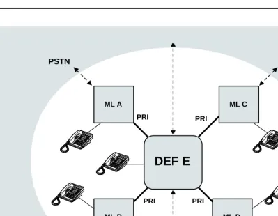
Figure 1–1 shows one way that systems can be connected in a private network.
NOTE:
All of the figures in this chapter use the following conventions:
■ A solid line represents a tandem trunk that connects one system in a network to another system in a network.
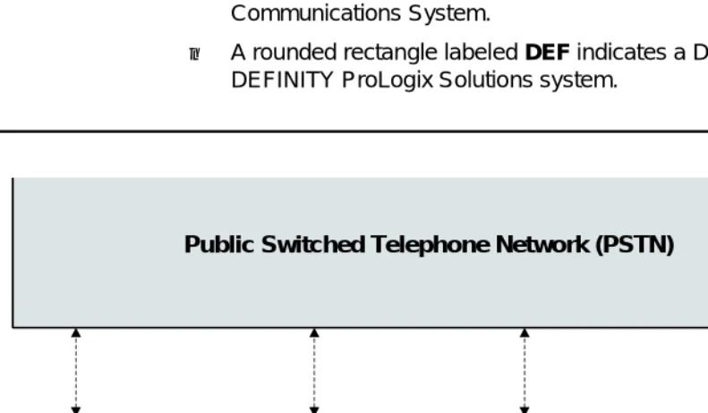
■ A dashed line represents a facility that carries a call to the PSTN.
■ A square labeled ML indicates a MERLIN LEGEND Communications System.
■ A rounded rectangle labeled DEF indicates a DEFINITY ECS or DEFINITY ProLogix Solutions system.
Figure 1–1. Series Configuration
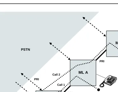
To make a call from System A to System C, a user at Extension 4321 dials to reach Extension 3699. The call travels over tandem trunks through System B to System C without using the PSTN to provide switching services. Systems B and C in this series configuration are called tandem switches.
Using another aspect of tandem switching, the user at Ext. 3699 employs Automatic Route Selection (ARS) normally in order to dial a number in the New York area code, , for example, where is the ARS code. In this
Public Switched Telephone Network (PSTN)
Tie PRI
PRI