Available online at: www.ijcncs.org ISSN 2308-9830
A Cross Layer Autonomic Enabled Architecture for VANETs
ALI FARAHANI1 and ESLAM NAZEMI2
1, 2
Electrical and Computer Engineering Faculty, Shahid Beheshti University, Tehran, IRAN
E-mail: [email protected], [email protected]
ABSTRACT
Similar to other ad hoc networks, VANETs need to change and adapt to their surrounding environment. Having various internal and external facilities to change network structure and parameters, VANETS are a good target for adaptive and managing systems. In order to achieve an autonomic system, self-management should be implemented in the system architecture. To address the autonomic self-management issues there is a need for a holistic architecture that works without considering predefined constraints and problem conditions. In this paper we present an autonomic enabled architecture using new component which enables cross layer connections. In this architecture we have customized elements of MAPE-K loop, namely Touchpoint and Knowledge, to enhance its applicability in vehicular ad hoc networks. By customizations in the concept of Touchpoint, our presented architecture supports the extraction of data from the cross layer connections between non-neighbors layers, In addition to the layers and their parameters. Furthermore we have classified the knowledge elements of MAPE-K loop in VANETs and described the role and usage of these elements. The applicability of this architecture is verified through simulation of two scenarios by in-team developed simulator. Simulation results show the applicability of the proposed architecture for VANETs in different situations.
Keywords: Autonomic Computing, VANET, Cross Layard Architecture, MAPE-K loop, Touchpoint, Intelligent Bus.
1 INTRODUCTION
A relatively new approach in networking is Vehicle Ad Hoc Networks (VANETs) that consist of vehicles with direct communication [1]. VANET is a type of Ad Hoc network in which a set of intelligent vehicular agents with wireless communication capability, interact with each other and also with special side road equipment. The main aims of VANETs, as mentioned in [2], could be summarized as (1) ubiquitous connectivity while on the road to mobile users, who are otherwise connected to the outside world through other networks at home or at the work place, and (2) efficient vehicle-to-vehicle communications that enable the Intelligent Transportation Systems (ITS). This ubiquitous and efficient communication platform provides safety and comfort for passengers.
High and unpredictable mobility is the nature of VANETs. Unlike MANETs in which nodes are deployed and planned based on a defined goal,
VANET node movement patterns do not follow network requirements.
VANETs, like other ad hoc networks, need to change and adapt to environment. This makes it critical to constantly control such networks, which is not possible by human monitoring. As mentioned in [3] “Current networks require ad-hoc operating procedures by expert administrators to handle changes -- from installing or removing network elements, to reconfiguring them. These configuration change management operations are costly, error prone, can result in unpredictable failures and inefficiencies, may involve costly recovery and limit the speed of network change dynamics.”
2001 observing that the main obstacle to further progress in the IT industry is a looming software complexity crisis. In this manifesto it is then stated that in order to overcome this obstacle the only option remaining is autonomic computing systems that have self-management capabilities based on high level administration objectives.
In order to achieve an autonomic computing system, self-management should be implemented in the system. Self-managing consists of four main parts: self-optimizing, self-healing, self-configuring and self-protecting. These capabilities could be enabled using MAPE-K loop which is a feedback cycle comprising Monitor, Analyze, Plan and Execute parts presented by IBM [4]. Knowledge plays a vital role at the core of MAPE-K loop.
Use of autonomic computing concepts in VANETs has been indirectly persuaded. An example is a research by [5] that considers a model based autonomic computing approach. However, the contribution of our paper is an architecture which directly considers autonomic computing in VANETs. The rest of the paper is organized as follows: in the next section, a brief overview of autonomic computing application in ad hoc network is provided. In section three our proposed architecture to enable autonomic VANETs is presented. In section four details of computer simulation used to validate the architecture is provided.
2 EXISTING MODELS FOR NETWORKS WITH AUTONOMIC CAPABILITY
Using autonomic computing concepts in networks was first mentioned in [6] and was then gradually applied to wireless, ad hoc and MANETs until reached VANETs in studies like [5].
As discussed in [6], network management is moving from being labor-intensive to software-intensive. Therefore a new architecture named NESTOR is presented. In this paper it is mentioned that the proposed architecture is automatic and enables self-configuring networks. This capability is achieved using a model based architecture that works by updating current environment model through network monitoring. Based on network requirements, decisions are first applied in this model and then, if successful, on the environment. In [5] Autonomic and self-adapting abilities in VANETS are studied from model based point of view.
In wireless networks automaticity is a little different than other types of network. As in [7], a wireless network without a predefined structure is synonymous of ad hoc network, and an ad hoc
network should be configuring and self-organizing. In fact every node in such network has enough intelligence to sense and discover other nearby nodes continuously, in order to make future decisions.
Autonomic computing concepts has been considered in many mobile networks studies since their scalability is severely restricted by the human operators’ ability to configure and manage the network in the face of rapid change of the network structure and demand patterns. The fact that these networks, as mentioned previously, have high levels of change makes it important to constantly manage and control network events. This issue was addressed in [8] where node movement is controlled by sending messages such that neighborhood topology is maintained using an algorithm.
Also in [9] an emergent approach is used that achieves a model for network communication in MANET by identifying node relationship across the area. In this solution the three steps required for self-organization are followed.
In general, as discussed in [2] because of the following reasons there is a great need for management in these networks:
• Ad-hoc deployment or lacking a predefined structure for deployment
• The network media being error prone • Limited resources and energy constraints
Moreover, if any of autonomy features is desired, this management should be autonomic-enabled. For example in order for the network to be self-healing, nodes that cannot move should play the messenger node for a while instead of search nodes.
In vehicular networks that are very similar to MANETs, autonomic computing is also used. Therefore it is tried to predict future events in these networks by achieving node movement models [10] and [11].
A lot of research has been done in self-organizing and self-managing VANETs. But these works lack a complete solution that supports all autonomic computing aspects. An example is [12] in which two self-organizing proactive and reactive protocols are introduced.
In this paper we present a model that unlike previous studies is based on autonomic computing concepts defined by IBM. In this model MAPE-K loop and the proposed architecture by DARPA is considered [13]. This approach applies autonomicty to the two bottom layers of DARPA architecture.
3 PROPOSED MODEL
In [14], connection point of the cycle is referred as ‘MAPE-K’ and the setting as ‘Touchpoint’. This phrase is referred to a section of presented Autonomic Architect through IBM which includes effecter, sensor, and managed element.
In the presented architect for the existing factors in VANETs in [13] besides the five main layers of TCP/IP, five applicable layers are also mentioned; which can be considered as peculiar layers for the VANETs. This Layered Architecture has been used in some of the VANET applications instead of Un-Layered Architecture. This layered architecture, because of the difficulties produced from complexity, obstructs the easy expansion of applications for VANET. Also the Layered Approach Architecture mentioned in [13] is not sufficient because of the adversities and restrictions it creates against the connection of different layers (blocking the direct connection of the layers which are not directly neighbors but in case of direct connection work better). Accordingly, the Sketch Approach Architecture is presented in [13]. In this architecture, the application layer has direct connection with its downward layers till the Single-Hop one. We with regard to this approach and the benefits mentioned for this approach, in our architecture, next to presenting a new component in architecture, we tried to support the Cross layer Architecture in addition to operation as autonomic.
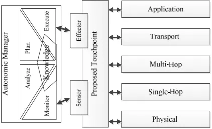
We try to present an architecture for the autonomic VANETs for enabling, self-managing, and self-adaptation in VANETs with adherence to the principle of the MAPPE-K cycle, presented by IBM [4], with alterations we perform in the way this cycle connects to its context. As it is said, the architecture we presented and it is shown in Fig. 1, the way of connecting between the loop and the operator context is put through proposed Touchpoint.
As it was mentioned, against the previous research, we were committed to the architecture presented by IBM for autonomic computing. In the paper, [5] has presented a frame work for self-adapting the VANETs, but it’s reached its goal with the model-based view. Meaning that with the model-based view, it has altered the four steps of loop, in a way the whole loop. We say that for
reaching the answer, there is no need for the effect of the type of the solution on the whole solution. Our aim is that with presenting this architecture, each solution with its features lay on this architecture; meaning that we want to express the general structure of activating the autonomic properties in the VANETs. As you can see in Fig. 1, the MAPE-K loop with the use of Touchpoint can see different layers, the properties of these layers and also the connection of these layers as a managed element. The process of monitoring and effecting on the layers and the connections are explained as we go on.
Fig. 1.The Holistic Schema of the Prosposed Architecture
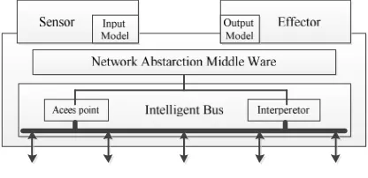
We were trying to alter and improve the Touchpoint presented by IBM for the Autonomic Architecture for the systems. This alteration led into the adapting of the presented architecture with the existing conditions in the VANETs. As you can see in the Fig. 2, because of the need for the cross layer connection mentioned in the presented architecture in [13], and also because of this reason that in addition to data and the effects we can extract from the VANET’s layered architecture and affect it, we can use the data transferred among layers; meaning that our entries are the data and the messages transferred among layers in addition to the layers and their parameters. We can also make decisions with the use of sniffing the between-layer data. Also our outputs are not only layers and their parameters, but also we can consider the between-layer message as an output. And also accessing, reading, and affecting these layers’ parameters through bus is possible. Accordingly an ‘Intelligent Bus’ is considered for the architecture, and its purpose is explained below:
the Application Layer and the Single-Hop layer, this connection with the architecture can be made in a way that the Application Layer gives its message to the intelligent bus, then this ‘Bus’ through changing the level and the type of message, convert the message into an apprehensible one for the single-hop layer to receive.
• This connection is sometimes maintained among the neighbor layers, in this case there’s no need to change the content and the type of the message. In these types of messages there’s no intelligence in the presented work of bus, but the monitoring which is mentioned as we go further.
• Monitoring of the data transformed among layers: this responsibility in other word is a type of data sniffing; meaning that the intelligent bus while transporting data among layers, knowledge and the data must be extracted and handed to the MAPE-K loop. For example, the intelligent bus sends several packets related to media stream from the Application Layer to the Data Service Layer. This bus reports the data related to the amount and percentage of sending such packet to the non-steaming packets, to its upper layers. Even in reporting it is possible to consider the recipient address of most of these packages.
• Maintaining connection among the
autonomic section and the layers of network: maintaining connection among the autonomic section and all the other layers of network is the main responsibility of this bus. This responsibility precisely includes maintaining connection among the Autonomic section and the layers of network for reading the data and details of these layers and also affecting these layers. In other words, establishing an entrance and exit interface of the data to these layers is with this bus.
As it is mentioned in the papers, which are about the Autonomic computing areas such as [15] and [16] that from architectural point of view are dedicated to solve problems, we can separate the autonomic section from other parts. By doing so,
the question area and the solution will be separated and cleared. In fact, for improving and accelerating the conditions for solving the question and making autonomic properties better and simpler for the different systems, it is better to separate the logic of Autonomic from the rest of the sections and layers of the system which present the responsibilities related to the system. For this, in our architecture, for separating the autonomic area from the question’s function, a wrapper and a middle-ware are put between the autonomic section and the practical part of the system. The job of this middle-ware is to cover the details of each side of this connection. In other words, the autonomic section should not be informed about the details of the of the network’s function section. In the other area of the science of software engineering, abstracting data in different layers is pointed out. Maybe another explanation which can be brought for the existence of such layer is following the same level of abstraction in the architecture we presented for the touch point.
Sensor and effecter in our architecture is placed on this middle-ware (Fig. 2), and they abstract their data from this always up to date projection of the network for the functional section of the network. Alterations in the type, fine and technical details of network in this layer are neutralized; and the Autonomic section is not affected truly by these alterations.
Fig. 2. The Proposed Touchpoint
All the needed data for the loop is passed through the filtering of the middle ware. Also all the decisions made by the loop, passes through this middle war and are put into practice on the different sections of each agents’ layers. In other words, the loop sees the whole network through this middle ware and the loop’s sense of the network agent, the one that the loop is working one, is a sense which perceives through this middle ware.
the input model knows that in what area it can add the data to the cycle and also it notices that which data is needed and must be read. Also the effecter with having this model notifies its area of options for effecting and also notices that what affects should be placed upon the context.
This model is defined and completed by the Execute and Monitor sections. As we continue how this function is done is explained.
As you can see in the Fig. 3, knowledge, which performs a vital and important role in the cycle, is divided into subcategories for a more precise explanation. In fact, in this architecture subcategories which generally form this knowledge are brought to let the architecture be able to run more efficiently. These subcategories are:
Self and environmental knowledge: this knowledge contains data from the knowledge and the innate skills of each agent, along with the agent’s information from the outer context. This knowledge at first is put into the agent as default, and over time with establishing a connection with situation knowledge, monitoring and analyzing these types of knowledge; and also the information it extracts from the context, improves and completes this knowledge. In fact this knowledge is always completing.
Situation Knowledge: this knowledge is related to the conditions given to the system during its existence, and this knowledge shows that the agent under what circumstances, based on what data, decides what to do. In fact in this knowledge there are the needs for data and the effects they must have on the context. Adding samples of this knowledge to the agent, results in the completion of the agent’s self and environmental knowledge.
Input Knowledge: This knowledge shows the awareness of the agent of the data which the agent is supposed to be aware of; meaning that this knowledge shows the agent what data it should receive as input. This knowledge results from the combination and the process of two other situation, and self & environmental knowledge. The need for data of each situation by concerning the skills that exists in the agent, in its self & environmental knowledge, is processed and the result would be the input knowledge of the agent. It will be specified that the agent must achieve what data and how to achieve. When the environment, and situation; input model is produced and is handed to the sensor. In fact the result of the process of these two types of knowledge would be input model and knowledge.
Output Knowledge: this knowledge shows the awareness of the agent of the effects it can have on the context; meaning that the agent with knowing
that where and with what lever can affect its context. This knowledge is the result of the combination of two knowledge of self & environment, and situation. In fact with analyzing the needs of the situation knowledge for affecting and also the agent’s abilities which exist in the self & environmental knowledge, output knowledge is produced. It will be specified that the agent must affect what spots. With achieving this knowledge from the combination and the process of the two mentioned knowledge, the Execute section has formed the output model with concerning the output knowledge and hands it to the effecter.
Now that we got familiar with the presented architecture, for showing the practicality of this architecture, two scenarios in different layers and also with the way the data is gathered and affecting the different layers are described and the results are brought. In the beginning we explain these scenarios.
As we mentioned, too much unpredictable movement is one of the VANETs’ features. Also in the urban context the density nodes in the network are not the same in all the places from geographical point of view. In places such as the city centers the context is denser and the parts away from the center, context is sparse. Also in the VANETs because of the wireless type of connection, the media used for transporting (air) is shared. Because of this when a node starts to transmit a message, the nodes which are in the same radio range are prevented from transmitting. This is true in both states that the protocol of transmitting node contains collision avoidance and collision detection.
This that the radio range be stable, would result into transmitting messages without considering the density of the nodes around; and in dense areas the traffic produced by us be high, and in sparse places the possibility of the connection of nodes to each other will be reduced; meaning that if we can change our radio range depending on the conditions, in dense areas we reduce the range so that in the collective media have less interruption with other nodes. Also in sparse areas we increase the radio range to stay connected with other nodes. This change, considering the conditions of the context, is a good place for autonomic computing. These scenarios in [17], [18] are analyzed precisely from network view.
message to all the surrounding nodes in a single cast way; but if after monitoring the local context, a number of nodes that want to observe this event are in our radio range, we can send the data through broad cast protocol. This would result in reduction of message traffic.
Fig. 3. Categorised Knowledge Elements
This action can be reached through analyzing the transmitting messages from the Application layer to the Data-Service layer and instead of a lot of single cast messages we can do a broad cast.
Based on the scenarios it is definite that in the first scenario only the inputs of each layer are taken into account; but in the second scenario the inputs of the cross layer are considered. In fact through simulation of these scenarios we can show that our architecture is capable of working under both cross layer and multi-layer conditions.
Now that we have initial familiarity with the scenarios, we go to the simulation.
4 SIMULATION
For the simulation of the mentioned scenarios, a simulator based on the Microsoft’s .Net Technology is developed in the team. This simulator based on the existing reference models for simulating multi agent and disturbed contexts and also network’s simulator reference models are developed. Because of this, the results achieved from scenario simulations in this simulator are reliable.
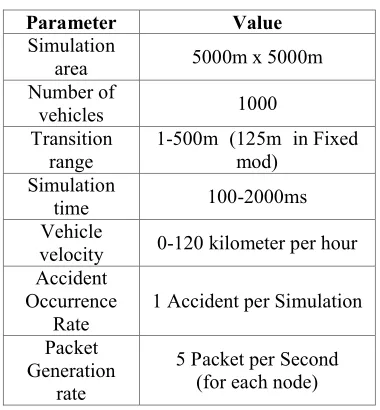
As mentioned in Table 1 simulated area is a square with the sides of 5km*5km which 1000 vehicles are in there. The way that the vehicles are placed in the area is a non-uniform distribution. Also the radio range of nodes is changeable from 1m to 500m. Under the condition that this radio range is fixed, amount is considered 125m.
The speed of vehicles is from 0-120 kilometer per hour and in each second the amount of change in this speed is applied. Also in simulation an accident (event) is considered which would take one 10 millisecond to transmit the data alongside. The number of sent packets by each vehicle is considered to be 5 packets per second in most of the simulations. This amount is apart from the
messages used for transmitting the accident. The time limitation for the simulation is also supposed to be from 100ms to 2000ms. The routing algorithm in this simulation is GPSR [19] in with no recovery strategy. By considering these amounts, the mentioned scenarios are simulated and the results are illustrated in the Fig. 4 to Fig. 6. In the following we explain the achieved results.
Table 1: Simulation Parameter
Parameter Value
Simulation
area 5000m x 5000m
Number of
vehicles 1000
Transition range
1-500m (125m in Fixed mod)
Simulation
time 100-2000ms
Vehicle
velocity 0-120 kilometer per hour Accident
Occurrence Rate
1 Accident per Simulation
Packet Generation
rate
5 Packet per Second (for each node)
The first scenario was applied with the time limitation from 100ms to 2000ms. As it is specified in the Fig. 4, network’s throughput under the un-autonomic condition is much less than the autonomic one. The reason is that several nodes were not connected to the other nodes in the first state to send/receive any message (this subject will be analyzed in the next section), and also because of consistency in the radio range in the first state, in network’s dense section in simulation, the density of sending messages along with noise were increased and the number of messages that don’t get the turn to be sent would increase.
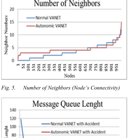
As it is specified in the Fig. 5, nodes’ dependency amount diagram, by considering their radio range is shown. The results achieved from 5 runs in the simulator. The time for simulating was considered 1000ms. As it is shown in autonomic network we have more uniformity in the number of nodes in the neighbor of each node; meaning that most of the nodes in their defined territory have three to five nodes as their neighbor, but in the un-autonomic state several nodes were not connected to any other node, and number of nodes also are neighbor with so many nodes.
Fig. 4. Received Message in Autonomic and non-Autonomic VANETs
Fig. 5. Number of Neighbors (Node’s Connectivity)
Fig. 6. Length of Message Queue in Difrent Situations of VANETs
For the second scenario one criterion (message queue length of each node) is considered for measurement. Reduction of message queue length, gained by autonomicity will result in a better network throughput compared to non-autonomic network. In the diagram of Fig. 6, as it is shown, the difference between the network without accident in a normal situation and with accident, and also the normal condition with control over sending by the MAPE-K loop in Autonomic
network properties are brought. This result is measured in a same condition with 10 number of repetition. The time for simulation was 520ms and the accident has happened at 500ms. As it is illustrated, the length of the queue in the normal state without accident in the best, autonomic network situation with accident is also very close to the best. The accident situation with non-autonomic network, result in much greater message queue length in nodes surrounding accident area. The reason that autonomic network achieves smaller message queue is that instead of sending many single cast streaming packets, we send one streaming broadcast packet.
5 CONCLUSION
VANETS have an unpredictable and uncontroll-able context. The node’s movement in this context is also unpredictable. Also networks own different parameters and variables for tuning in these networks. These networks like other wireless ad hoc networks need adaption to their context, and must be able to adapt themselves to their context as they go on with living. Because of these properties, VANETs are a desirable choice for autonomic computing. In the VANETs’ domain attention is paid to Self-Configuring, Self-Adaptation, and autonomic property, but this attention has been only for making a solution just for one question and the answer to the mentioned question. One of the things that this view has overlooked and had a holistic view is [5]. In this paper, against previous works, we tried to present an architect for VANET and also to consider the question wholly; meaning that to not limit methods for presenting different scenarios on this architecture. Also in this architecture, we were loyal to the MAPE-K loop as the heart of the presented architecture by IBM for Autonomic computing. With the use of the presented architecture we can through using any view on the answer, transform VANET to an Autonomic VANET.
the results achieved from simulation we can state that the presented architecture is a cross layer autonomic enabled architecture for the VANETs, which against the previous works has a holistic view upon the autonomic VANET problem.
6 REFERENCES
[1] S. Yousefi, M. Siadat Mousavi, and M. Fathy, “Vehicular Ad Hoc Networks (VANETs):
Challemges amd Perspectives,” 6th
International Conference on ITS
Telecommunications Proceedings, 2006. [2] S. Misra, I. Woungang, and S.C. Misra, Guide
to Wireless Ad Hoc Networks, Springer-Verlag New York Inc, 2009.
[3] a V. Konstantinou, D. Florissi, and Y. Yemini, “Towards self-configuring networks,”
Proceedings DARPA Active Networks
Conference and Exposition, 2002, pp. 143-156. [4] J.O. Kephart and D.M. Chess, “The vision of autonomic computing,” Computer, vol. 36, 2003, p. 41–50.
[5] A. Ceccarelli, J. Grønbæk, L. Montecchi, H.-P. Schwefel, and A. Bondavalli, “Towards a Framework for Self-Adaptive Reliable Network Services in Highly-Uncertain Environments,” 2010 13th IEEE International Symposium on Object/Component/Service-Oriented Real-Time Distributed Computing Workshops, Ieee, 2010, pp. 184-193.
[6] Al.V. Konstantinou, D. Florissi, and Y. Yemini, “Towards self-configuring networks,”
Proceedings DARPA Active Networks
Conference and Exposition, IEEE Comput. Soc, 2002, pp. 143-156.
[7] C. Elliot and B. Heile, “Self Organize Self healing Wireless Networks,” Aerospace Conference Proceedings, 2000.
[8] S. S-Basu and A. Chaudhuri, “Self-adaptive Topology Management for Mobile Ad-hoc
Network,” JOURNAL-INSTITUTION OF
ENGINEERS INDIA PARTET
ELECTRONICS AND
TELECOMMUNICATIONS ENGINEERING DIVISION, vol. 84, 2003, p. 7–13.
[9] S.A. Brueckner and H.V.D. Parunak,
“Self-organizing MANET management,”
Engineering Self-Organising Systems, 2004, p. 20–35.
[10]J.I. Agbinya, G.P. Navarrette, and H. Al-Jaʼafreh, “A Study and Review of Self Managed Vehicular Networks,” International
Journal of Electronics and
Telecommunications, vol. 56, Nov. 2010, pp. 433-444.
[11]A.K. Banik, Routing Protocol with prediction based mobility model in Vehicular Ad Hoc Network ( VANET ) Introduction :, 2010. [12]M. Cherif, S.M. Senouci, and B. Ducourthial,
“Vehicular network self-organizing
architectures,” GCC Conference & Exhibition, 2009 5th IEEE, IEEE, , p. 1–6.
[13]H. Füßler, M. Torrent-Moreno, M. Transier, A. Festag, and H. Hartenstein, “Thoughts on a protocol architecture for vehicular ad-hoc networks,” Proceeding of WIT 2005, 2005, p. 41–45.
[14]E. Manoel, M. Nielson, A. Salahshour, S.
KVL, and S. Sudarshanan, Problem
determination using self-managing autonomic technology, IBM International Technical Support Organization, 2005.
[15]D. Weyns, S. Malek, and J. Andersson, “On decentralized self-adaptation: Lessons from the trenches and challenges for the future,” Proceedings of the 2010 ICSE Workshop on Software Engineering for Adaptive and Self-Managing Systems, ACM, 2010, p. 84–93. [16]D. Garlan, S.-W. Cheng, a-C. Huang, B.
Schmerl, and P. Steenkiste, “Rainbow: architecture-based self-adaptation with reusable infrastructure,” Computer, vol. 37, Oct. 2004, pp. 46-54.
[17]S. Das, A. Nayak, S. Ruhrup, and I. Stojmenovic, “Semi-Beaconless Power and Cost Efficient Georouting with Guaranteed Delivery using Variable Transmission Radii for Wireless Sensor Networks,” 2007 IEEE Internatonal Conference on Mobile Adhoc and Sensor Systems, Ieee, 2007, pp. 1-6.
[18]M.M. Artimy, W. Robertson, and W.J. Phillips, “Assignment of dynamic transmission range based on estimation of vehicle density,” Proceedings of the 2nd ACM international workshop on Vehicular ad hoc networks - VANET ’05, 2005, p. 40.