www.ijaera.org 2016, IJA-ERA - All Rights Reserved 192
Scaling of Air Blast Effect on Square Metal
Plates with Experimental and Numerical
Methods
Mohammad Ansari, Mehdi Torabi Goodarzi*, Mohammad palizban& Morteza Gholami
Structure Analysis Central Lab, Hemmat Highway, Tehran, IRAN
Abstract: Today, scaling laws are used frequently to evaluating the blast effects on structures and soil. These laws significantly are used for generalizing the results of scaled-down experimental tests to real and full- scale tests. in this paper, with both of experimental test and numerical simulation by LS-DYNA program software, we are proceeding to scaling of air blast effect in close- ranges on st-37 steel plates with square geometry and completely bonded perimeter. Full-scale experimental tests which include of real scale structures and charges, in preparation, as well as data recording and final results, are implicated of high costs and lower level of safety. So, scaled-down experimental tests are properly advantageous and desirable. Hence, assessing the results of these experimental tests are the main subject of this paper. Scaling of geometrical parameters is done based on geometrical similarity and blast effect scaling by well-known Hopkinson’s law. At the end, a very good agreement obtained between results of numerical simulation and experimental test. Therefore, the main message of this paper is that by using scaling laws, one can prevision dynamical response of metal plates that exposed on real scale blasts in close ranges.
Keywords:Air Blast, Scaling, LS-DYNA, Steel Square Plates, Dynamical Response
I. INTRODUCTION
In past decades, expensive activities have performed in field of explosive loadings. Importance of research in this domain, not only for observing the damage caused by explosion, but in order to predict the vulnerability of human and structures to blast, and design, development and fabrication of blast resistant material, too. A key of success in defense projects is accurate understanding the behavior of metal plates that exposed to explosions. According to subject of blast wave in metals, dynamical response of structure depends on several parameters such as distance from charge, weight of charge, type of metal plates, so on [1-7]. Performed studies in this domain, besides illustration of different destruction states, also describe the relations between deforming and rupturing of constrained metal plates that subjected under blast loading. For the first time, destructive states of metal plates have been described by Menkes & Opat, for cases that metal shafts subjected under explosion loadings [8]. Performed classification is as follows: a) large non-elastic deforming, b) rupturing, c) shear destructing.
www.ijaera.org 2016, IJA-ERA - All Rights Reserved 193 while for larger explosions there is need for numerical simulations and experimental tests. Raftenberg has performed series of studies about small blast loadings on metal discs, and compared the results of experimental tests with numerical simulations of finite element method.
According to scaling of blast effects in metal structures, performed studies and works, in comparison with other fields of explosion, are not broadened.
With last information and research of authors, scaling the effect of relatively big explosions on metal plates in close ranges, has performed rarely (or because of classification levels, a few have been published). A closest report that is similar to present work, have reported by Neuberger in 2007 [1]; However, in fundamental parameters such as charge type, shape of charge, material and geometry of metal plates, are different.
This study includes the numerical simulations by finite element method and experimental tests of air blast effect on metal square plates. Numerical calculations and experimental tests have performed by scale factor of s = 5 (this factor means scale of 1:5). Result and main output of this study is this point that, by using of scaling laws, one can analyze the metal plates that subjected under real scale blast loadings in air and close distances.
II. MATERIAL AND METHOD
A. Fundamental theory of scaling
One of the most important points for scaling of any phenomena is physical evaluation of that phenomenon. Performing of experiments on model and scaled down sample before creation of main and bigger model is so necessary and logical. However, we must know that how can generalize the results of performed tests on model and scaled down sample to main and real scale sample.
Scaling principles and relations between real and sample model, have been formulated. In the following, scaling parameters are mentioned in kind of relations between sample model, Mt and main model, P:
Dimensions in relation to scaling coefficient, are linear:
(1)
Angles are similar:
(2)
Densities of materials are similar:
(3)
Stresses are same for any material:
(4)
www.ijaera.org 2016, IJA-ERA - All Rights Reserved 194 (5)
Loadings are similar and must consider in scaled points:
(6)
Deforming measure for specific characteristic times is ratio to scaling coefficient:
(7)
Angular deforming is similar:
(8)
It must be noted that, there are several phenomena that are not scalable with above principles. For example, gravitational force can’t be scaled from geometrical scaling principles. However, in here, we are involved with high accelerations, so, gravitational forces are not important and can be neglected.
Most conventional method in scaling of spherical shock waves, is using of Hopkinson's scaling rules with third root. This law claims that, when two charges from same type and with similar geometrical shape but with different weights are exploded in a medium, then in specific scaled distance, similar explosion waves will be created. Relations of hopkinson's law for air blast, are as follows:
(9-a)
(9-b)
(9-c)
Where Z is scaled distance, τ*, scaled characteristic time for shock wave; I*, scaled impulse; R
distance from center of charge and E energy outcome from explosion. In above relations, it is remarkable that, E can be substituted by weight of explosive material, W.
B. Numerical simulation
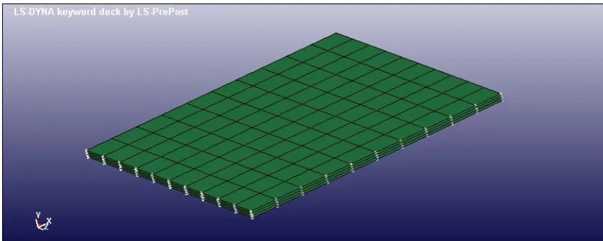
In this paper, for performing numerical simulation of considered problems, we have used Arbitrary Lagrangian Eulerian (ALE) method in LS-DYNA nonlinear code. This finite element code has high ability in simulation of complicated engineering problems, such as simulation of explosions and their effects on different structures. In this program, particular material models and equations of state have been used for every section. The aim of this simulation is investigation the behavior of given metal plates and estimation of deforming level of them. Numerical simulation has performed with finite element method in three general stages. (i) First stage includes the creation of geometrical model of problem such as explosive charge, air and metal plate by using of Ls-Prepost software, (ii) In second stage, nonlinear dynamical analysis and (iii) post processing the results of analysis have performed by Ls-Prepost software for interpretation of obtained results.
www.ijaera.org 2016, IJA-ERA - All Rights Reserved 195 equations of state are used. According to this fact that problem has axial symmetry, problem modeled by ratio of 4:1 and naturally the solving time of problem is reduced. Applied axial symmetry is presented in Fig.1.
Figure 1: Applying the boundary conditions of symmetry
Material model that considered for metal plate, was Johnson-Cook model that its equation is as follows:
(10)
Where A, B, C, n and m are coefficients of material that were mentioned in Table 1. is effective strain and is the rate of effective plastic strain in the rate of reference strain of and
where T* is the temperature of materials and T*room is room temperature and is melting temperature.
Table 1: selected coefficients for material model
A (MPa) B (MPa)
C n
m
365 510
0.0936 0.9
0.917
Along with Johnson-Cook equation, Polynomial equation of state has been used, which is a linear equation versus internal energy and is as follows:
(11)
Where and are zero if , that is the ratio of instant density to initial
density.
Used equation of state for explosion products is Jons-Wilkins-Lee equation (JWL) that is as follows:
(12)
www.ijaera.org 2016, IJA-ERA - All Rights Reserved 196 ratio of resulting gases from explosion to initial condition of explosive material and E' is energy per unit volume.
Equation of state for intermediate fluid, that is air, is polynomial equation of state:
(13)
Where, , and is ratio of instant density to initial density. C1….6 are polynomial coefficients and E* has pressure unit. For modeling the air, one can use Gamma law. Hereon, , and , where γ is the ratio of specific heat capacities. So, equation 13 transforms to:
(14)
C. Test configuration
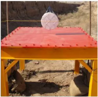
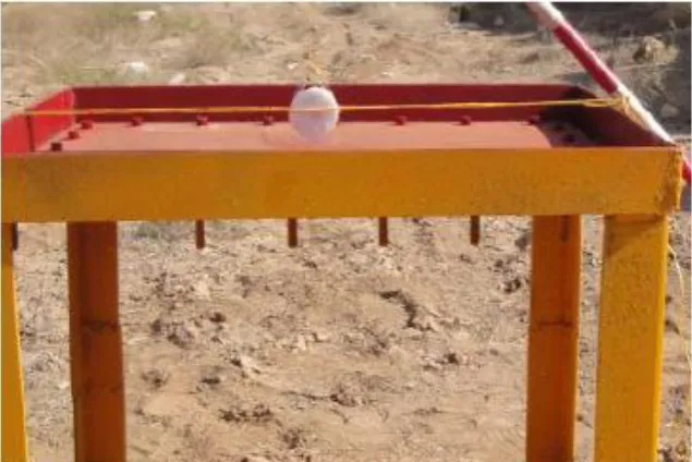
One cylindrical explosive charge from C4 with 7kg weight in distance of 10 cm from center of steel plate, thickness of steel plate was 15 mm and scale factor of 1:5; and one cylindrical explosive charge from C4 with 0.056 kg weight in distance of 2 cm from center of steel plate with thickness of 3 mm, was examined. In this test, for all of explosions, we have used a number 8 electrical detonating agent. Structure of accomplished tests is presented by photograph in Fig. 2 and Fig. 3 for full- scale and scaled- down test, respectively.
www.ijaera.org 2016, IJA-ERA - All Rights Reserved 197 Figure 3: Structure setup of scaled- down test
Schematic diagram of performed setup for all of the tests is shown in Fig. 4. Where L is the length side of steel plate, R distance from center of plate to center axis of explosive charge and - is maximum of deformation.
Figure 4: Schematic diagram of all of the tests
III. RESULTS AND DISCUSSION
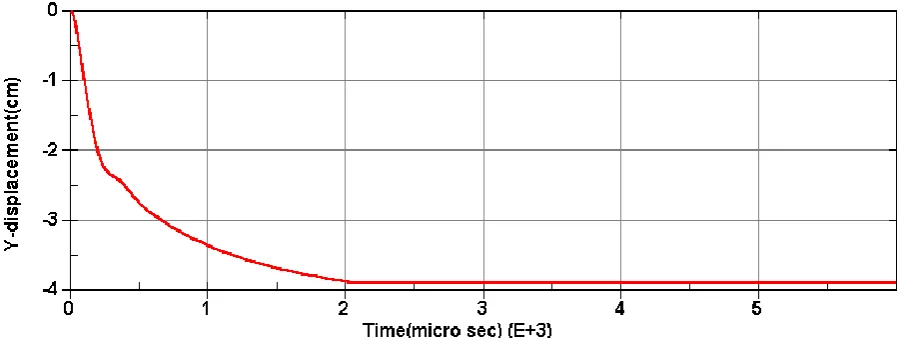
A. Simulation Results
www.ijaera.org 2016, IJA-ERA - All Rights Reserved 198 Figure 4. Constructed central deforming quantity in scaled- down case
Figure 5: Constructed central deforming quantity in full- scale case
Also, counters of created plastic strain for both cases are presented in Fig 7 and Fig. 8. As we can see from following pictures, the maximum of created strain is constructed in central elements, because charges are precisely located in the middle of metal plates.
www.ijaera.org 2016, IJA-ERA - All Rights Reserved 199 Figure 7: Counter of plastic strain in full- scale case
B. Experimental test results
After the blast and examining the deformation created by resulting impact of explosion, we have observed that shape and deformation caused by blast is different in full- scale and scaled- down sample. As can be seen from Fig. 9 and Fig. 10, depth of created central deformation in scaled- down and real- scale samples is 3.2 and 14.5 cm, respectively. So, scaling with scale factor of 1: 5 for performed test has been vindicated by 91%.
www.ijaera.org 2016, IJA-ERA - All Rights Reserved 200 Figure 9: Measurement of created central deformation in full- scale case
Results of numerical simulation and experimental tests are summarized in table 2.
Table 2: summarized results of numerical and experimental tests
s t (mm) L (cm) W (kg) R (cm) δ/t Experimental δ/t numerical 1 15 200 7 10 9.70 8.93 5 3 40 0.056 2 10.70 12.33
Obtained data in above table show that performed simulation results are close to real scale and there is a good correlation between numerical simulation and results of experimental tests.
IV. CONCLUSION
Scaling of air blast effect was performed on st-37 steel plates in both methods of numerical simulation and experimental test. Where, results of numerical simulation are about 90% close to experimental test and the results of scaled- down test in both method are precisely extendable to real-scale results.
Performing the real- scale blast includes high financial costs, safety problems and hard data accumulation. So, with performing the scaled down test and by using suitable scaling laws; one can estimates the results of real- scale test, by using results of scaled- down tests. In fact, by using the scaling law, not only the destruction caused by real scale blast, but, human trauma and structure demolition are anticipated; and we can use these information for fabrication of resistant and refractory materials to explosions in different environments, where software simulations are very useful in this area.
Conflict of interest: The authors declare that they have no conflict of interest.
www.ijaera.org 2016, IJA-ERA - All Rights Reserved 201 REFERENCES
[1] G. Eason, B. Noble, and I. N. Sneddon (1955). On certain integrals of Lipschitz-Hankel type involving products of Bessel functions. Phil. Trans. Roy. Soc. London, vol. A247, pp. 529–551.
[2] J. Clerk Maxwell (1892). A Treatise on Electricity and Magnetism. 3rd ed., vol. 2. Oxford: Clarendon, pp.68–73. [3] I. S. Jacobs and C. P. Bean (1963). Fine particles, thin films and exchange anisotropy. In Magnetism, vol. III, G.
T. Rado and H. Suhl, Eds. New York: Academic, pp. 271–350.
[4] Y. Yorozu, M. Hirano, K. Oka, and Y. Tagawa (1987). Electron spectroscopy studies on magneto-optical media and plastic substrate interface. IEEE Transl. J. Magn. Japan, vol. 2, pp. 740–741, [Digests 9th Annual Conf. Magnetics Japan, p. 301, 1982].
[5] M. Young (1988). The Technical Writer’s Handbook. Mill Valley, CA: University Science.
[6] D. Kornack and P. Rakic (2001). Cell Proliferation without Neurogenesis in Adult Primate Neocortex. Science, vol. 294, pp. 2127-2130, doi:10.1126/science.1065467.
[7] P. Kumar, S. R. Chauhan (2016). An Investigation on cutting Forces and Surface Roughness during Hard Turning of AISI H13 Die Tool Steel with CBN Inserts using RSM., International Journal of Advanced Engineering Research and Applications. (IJAERA) , Vol. , Issue 9, pp. 345-356