Abstract
Recently, the weapon systems are more and more complex and the demands for handling and maintaining these complex systems effectively are increased. For this reason, industrial control network had been developed for many years and the needs for the development of a totally networked automation environment are raised. To meet these requirements, networked motion control systems tend more and more to replace the traditional solutions. In this paper, the XY platform motion control system employing RTEX (Real Time Express) network which is one of the Ethernet based vender-oriented industrial networks is tackled. The network motion controller which generates motion profile and outputs the pulse train is implemented and is applied to XY platform. As results, it is shown that the proposed network motion controller works properly to control the XY platform and monitors the system easily through network.
Keywords: Network motion, motion controller, motion profile, XY platform control
1. Introduction
In recent years, systems for manufacturing and production are becoming more and more complex. More and more motorized devices are being used in manufacturing or production lines to attain the complex motions that are required for today’s sophisticated manufacturing techniques. To control the devices in these lines, analog control has been used, but the vast amount of wiring required for analog control makes it difficult to connect a large number of devices. The functions that analog control can offer are too limited to satisfy the demand for higher levels of control. Now, control using digital communications is increasing in demand and taking the place of analog control. Also, to meet the demand for increased productivity, a cycle time that is one second or even one millisecond shorter will result in a shorter control cycle between control devices. Accordingly, to get these required results, the demand for high-speed digital communications has been increasing. On the other hand, customers frequently change the models and manufacturers of their control devices to take advantage of rapidly decreasing prices and improvements in function and control performance. Most manufacturing equipment consists of two sections: a drive section and an I/O control section. Customers want to control both of these sections with the use of only one digital communications line. With regards to motion control connectivity, reducing the number of cables and increasing design flexibility is always a key. For this reason, industrial control network, so called fieldbus, had been developed for many years and the needs for the development of a totally networked automation environment are raised. Furthermore, due to the quick evolution of manufacturing processes, the demand for more flexible automation systems is on the rise. To meet these requirements, networked motion control systems tend more and more to replace the traditional solutions. The primary advantages of a networked motion control system are reduction of system wiring, easy of system diagnosis and maintenance, and high system agility, etc. Recently, because of the quick manufacturing
Byounghee Kim, Sinwoo Song , Euicheong Hwang, Kyoungdyuk Rho, Jonghyo Lee
*,$Artillery System Team, Hanwha Land System R&D Center, Korea
#Agency for Defense Development, Korea
(Received 15 August 2018; accepted 20 February 2019)
processes, the Ethernet based industrial network becomes commonly used in many motion control areas.
Motion Controller
. . .
Motion Control Network
Motor Motor Motor
Drive Drive Drive
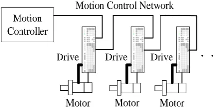
Figure 1: Network motion control system.
Figure 1 shows the networked motion control system which is composed of servo controllers with network interface, motors, a motion controller and a control network. Networked motion requires a control network that supports high-speed transmission of control command and feedback information. Recently researches about networked motion control systems have been increased with years. Lorenz presented three approaches which are synchronized master command approach, master-slave approach and relative dynamic stiffness approach 1. Fuzzy logic coupling control and neuro-controller approach is also endeavored 2,3. Niemann discussed fieldbus-based motion control strategies 4. Samaranayake presented a speed controller for distributed motion control via Ethernet 5. Hsieh was put forward a CANBUS-based motion control approach 6.
In this paper, the network motion controller is implemented using RTEX network which is the Ethernet based network and applied to shaft motor test bed to show the control performance. In section 2, the motion control networks are introduced. The implementation of the network motion controller is discussed in section 3. In section 4, the experimental results that are applied to shaft motor bed are analyzed. Finally, we make conclusions in section 5.
2. Motion Control Networks
Many Ethernet based control networks have been developed for use in networked motion control systems. In this paper, vender-oriented networks are introduced since the RTEX which is one of the vender-oriented networks is applied. The main reason of selection of the RTEX is that the RTEX network can control 16 axes basically and be extended up to 32 axes without increasing communication time. Another reason is the communication speed which is 100 Mbps and application examples. Still another reason is that many industries have been used Panasonic’s drive and motor for many years which means easily upgrade to network type system from non-network type system.
3. Implementation of Network Motion Controller
3.1. Hardware Design
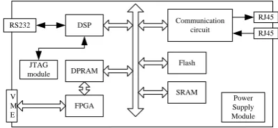
The proposed network motion controller mainly consists of three parts: motion profile generation part, communication part, and bus interface part. Figure. 2 shows the proposed network motion controller block diagram.
DSP Communication circuit
JTAG
module DPRAM
FPGA
Flash
SRAM RS232
RJ45 RJ45
V M E
Power Supply Module
Figure 2: Proposed network motion controller
The motion command and monitoring data can transmit and receive through the RS232 port. Since the XY gantry system consists of VME bus system, FPGA plays a role of VME interface. The communication circuit consists of Panasonic communication chip and PHY chip which is commonly found in Ethernet device and connects a link layer device to a physical medium since RTEX is Ethernet based motion control network. The communication period of the proposed network motion controller is 0.5 ms and can control up to 32 axes by itself. As mentioned before, one advantage is that even the axis increased up to 32, the communication period is fixed at 0.5ms.
3.2. Motion Profile Planning
0 0.1 0.2 0.3 0.4 0.5 0.6 0.7 0.8 0.9 1 0 0.1 0.2 0.3 0.4 0.5 0.6 0.7 0.8 0.9 1 Velocity Normalized Time N o rm a li z e d V e lo c it y
0 0.1 0.2 0.3 0.4 0.5 0.6 0.7 0.8 0.9 1 0 0.2 0.4 0.6 0.8 1 1.2 1.4 1.6 Acceleration Normalized Time N o rm a liz e d A c c e le ra ti o n
0 0.1 0.2 0.3 0.4 0.5 0.6 0.7 0.8 0.9 1 -5 -4 -3 -2 -1 0 1 2 3 4 5 Jerk Normalized Time N o rm a li z e d J e rk
0 0.1 0.2 0.3 0.4 0.5 0.6 0.7 0.8 0.9 1 0 0.1 0.2 0.3 0.4 0.5 0.6 0.7 0.8 0.9 1 Distance Normalized Time N o rm a liz e d D is ta n c e
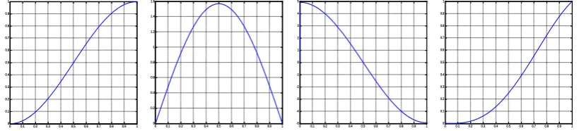
Figure 3: proposed motion profile
The profiles are generated for the arbitrary time t and normalized. Since the sine
wave function is applied for the velocity profile, the shape of the acceleration and jerk profile is also sine wave function which means no discontinuity and can reduce the vibration of the manufacturing equipments consequently. The motion profile can simply be asymmetry by changing acceleration and deceleration time interval.
4. Experiment results
4.1. XY Gantry System
The target XY gantry system consists of the six shaft motors. The shaft motors are direct-drive linear servomotors that consist of a shaft with laminated magnets and cylindrically wound coils controlled by the flow of current. These motors are a new generation of actuators based on a very simple construction that has drives which use magnetic circuits consisting only of permanent magnets and coils, and subsequently produces a wide range of characteristics. These characteristics include precision positioning and high, low and constant speed driving, making them suitable for a highly diverse range of applications. Unlike the general rotary type motors, the shaft motor uses the linear scale as a feed back signal. The XY gantry system use the GHC shaft motor which the rate force is 190N for X axis and 250N for Y axis, respectively and available stroke is 2500mm for X and Y axes. Since the shaft motor is applied for the XY gantry system, the linear scale is used for feedback. The Mitutoyo’s ST 700 series absolute linear scale is chosen which the
resolution is 0.5 m. Figure. 4 shows the 3D layout of the shaft motor test bed.
Y11 Y22
X1
X2
Y12 Y21
magnetic flux U W V
U W V
driving force
f
fload + frip + fd
magnet
coil
N S N S N S N S
x(t)
Figure 4: 3D layout of XY Gantry Figure 5: Structure of Shaft Motor
According to the 12, the dynamics of the shaft motor can be simplified as
) ( )
(t k i t
f = f q (1)
) ( ) ( ) ( )
(t mv Bv f t f x f t
f = + + load + rip + d (2)
where, x(t) is the motor position, v(t) and iq(t) are the time-varying motor terminal
voltage and the equivalent armature current, respectively. kf is the force coefficient related
with flux linkage of a shaft motor; m is the mass of a carriage; f(t) and fload(t) are the
developed force and the applied load force, respectively. and frip(x) denote the force ripple,
fd(t) denotes the other force disturbances. By neglecting the nonlinear portion in Eq. (2)
and combining with Eq. (1), the following linearized equation can be acquired.
v k
B v k
m t i
f f
q()= + (3)
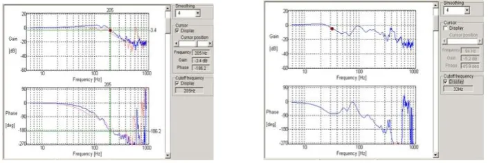
Even the shaft motor can be modeled as Eq. (1) and Eq. (2), it is only for one axis and the movement of the combination of the six motors is highly nonlinear since each motor is coupled in the XY gantry system. Because it is quite hard to get exact mathematical model of the XY gantry system, the FFT analysis is normally used to understand the system characteristics in the field. The overall structure of the control system is shown in Figure. 6.
V
M
E
b
u
s
Operation System
SD
8000 HP J4110AProCurve
Industrial PC
Network Motion Controller
shaft motor
RX
TX
XY Gantry System
Figure 6: Overall structure of the control system.
The overall system can be divided into three parts: Operation System, Network Motion Controller, and XY Gantry System. The operation system can communicate with the network motion controller by the VME bus and the network controller is connected to the target application by RTEX network which is configured as ring topology.
4.2. Experiment results
Before applying the proposed network motion controller, the FFT analysis is performed to get XY gantry system characteristics. Figure 7 shows the FFT results for the front X axis and front Y axis, respectively.
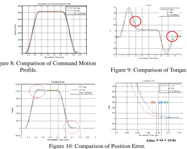
Figure 8 ~ Figure 10 show the motion characteristic by applying the proposed motion profile. Three motion profiles-S curve, proposed S curve, polynomial S curve-were compared and the setting time is improved when using the proposed motion profile.
0 0.1 0.2 0.3 0.4 0.5 0.6 0.7 0.8 0.9 1
0 500 1000 1500 2000 2500 3000 3500
Comparison of Command Motion Profile
Normalized Time (sec)
S
p
e
e
d
(
r/
m
in
)
NC Org NC Rev Sim 2ndOrder
Figure 8: Comparison of Command Motion
Profile. Figure 9: Comparison of Torque.
Figure 10: Comparison of Position Error.
5. Conclusion
In this paper, the network motion controller employing RTEX is introduced. The experiment target is XY gantry system consisting of six shaft motors and each three motors move together as front gantry and rear gantry. Since three motors are coupled, it is very difficult to get exact mathematical model. Therefore, the FFT is performed to understand system characteristics. From the results, the proposed network motion controller works properly in the XY gantry system. The setting time is under 229 and the servo parameter can be handled through the network. The proposed network motion controller can be applied to the other manufacturing equipments and the robot based applications. The future work is implementation of control scheme in the proposed network motion controller to make it general controller. By this, the network motion controller can be used more widely in motion control area.
6. References
1. R. D. Lorenz and P. B. Schmidt, Synchronized motion control for process automation,
Proceedings of the 1989 IEEE industry applications annual meeting, 1989, 1693 –1698.
2. P. R. Moore and C. M. Chen, Fuzzy logic coupling and synchronized control of multiple
independent servo-drives, Control engineering practice,1995, 3, 1697 – 1708.
3. H. C. Lee and G. J. Jeon, A neuro-controller for synchronization of two motion axes,
International journal of intelligent system1998, 39, 571 – 586.
4. H. Niemann, Synchronised motion using fieldbus linked electrical drives – an
5. L. Samaranayake, S. Alahakoon, and K. Walgama, Speed controller strategies for distributed motion control via Ethernet, IEEE international symposium on intelligent control, 2003, 322 – 327.
6. C. C. Hsieh, A. P. Wang, and P. L. Hsu, CAN-based motion control design, SICE annual
conference, 2003, 2504 – 2509.
7. S. Macfarlane and E.A., Croft, Jerk-bounded manipulator trajectory planning: design for
real-time applications, IEEE Transactions on Robotics and Automation, 2003, 19(1), 42 – 52.
8. P. Lambrechts, M. Boerlage, and M. Steinbuch, Trajectory planning and feedforward
design for electromechanical motion systems, Control Engineering Practice, 2005, 13, 145 – 157.
9. B.G. Dijkstra, N.J. Rambaratsingh, C.W. Scherer, O.H. Bosgra, M. Steinbuch, and S.
Kerssemakers, Input design for optimal discrete time point-to-point motion of an
industrial xy-positioning table, Selected Topics in Signals, Systems and Control, 2001, 9- 14.
10. H. Z. Li, Z. Gong, W. Lin, and T. Lippa, A New motion control approach for jerk and
transient vibration suppression, IEEE International Conference on Industrial Informatics, 2006, 16(18), 676 – 681.
11. P. H. Meckl, P. B. Arestides, and M. C. Woods, Optimizebd s-curve motion profiles for
minimum residual vibration, Proceedings of the American Control Conference, Philadelphia, 1998, 2627 – 2631.
12. K. K. Tan, Precision motion control with disturbance observer for pulse