IJIRT 142559
INTERNATIONAL JOURNAL OF INNOVATIVE RESEARCH IN TECHNOLOGY136
Real time Implementation of Sliding mode Controller for Speed
Synchronization of Dual Servo system
Bharat R Vala, Prof. Manisha C Patel
Applied Instrumentation (Instrumentation and control dept.), L D College of Engineering, Ahmedabad
Abstract—In order to attain higher manufacturing efficiency,
“dual (two) servo systems” are widely used in advanced Computer Numerical Controlled (CNC) machine tools. A well-known example is the linear motor driven gantry type of micro machine tools where dual servos are employed to drive the heavier gantry axis. I propose Sliding Mode controllers for the servo drive system. To get high performances, we have to control the input variable in uncertainties and disturbance. Two cases are discussed for each control scheme. Normal case, parameter variation case, and disturbance case are considered. When PI Controller is implemented in the system, its gives better performance compared to other controllers, but results are ineffective for disturbance case. Sliding mode control is then implemented. It is observed that system performance increases when compared to PI for parameter variation case and for disturbance case which shows the robustness of SMC.
Index Terms—sliding mode control, cross- coupled controller,
servo motor, servo system, dual servo system.
I. INTRODUCTION
In order to attain higher manufacturing efficiency, “dual (two) servo systems” are widely used in advanced Computer Numerical Controlled (CNC) machine tools. A well-known example is the linear motor driven gantry type of micro machine tools where dual servos are employed to drive the heavier gantry axis. Recently, dual servos are also used in spindle systems. “Double sided milling” is an example where two spindles are required to obligingly remove material on both sides of a work piece.
II. INTRODUCTIONTOMULTI-AXIS SYNCHRONIZATION
The expression "motion axis" alludes to one level of freedom, or forward and rearward kineticism along one heading. It might be direct or turning kineticism, and may take the type of a carpet lift, a revolving blade, or numerous different sorts. At the point when two or more tomahawks of kineticism are included on a solitary machine, that machine is utilizing multi-pivot kineticism. The axis may be working freely, or moving together. The desideratum for multi-axis synchronization arises whenever the axes must move together, and the relationship between their respective forms of kineticism is consequential.
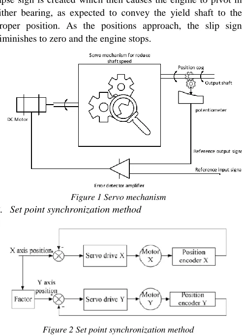
A. Servo motor and its working
A servomotor is a servomechanism. All the more particularly, it is a shut circle servomechanism that uses position criticism to control its movement and last position. The information to its control is some sign, either simple or advanced, speaking to the position told for the output shaft. The motor is matched with some sort of encoder to give position and rate input. In the least complex case, just the position is measured. The deliberate position of the yield is contrasted with the order position, the outer information to the controller. On the off chance that the yield position varies from that needed, a lapse sign is created which then causes the engine to pivot in either bearing, as expected to convey the yield shaft to the proper position. As the positions approach, the slip sign diminishes to zero and the engine stops.
Figure 1 Servo mechanism B. Set point synchronization method
Figure 2 Set point synchronization method
IJIRT 142559
INTERNATIONAL JOURNAL OF INNOVATIVE RESEARCH IN TECHNOLOGY137
C. Feedback synchronization method
Figure 3 Feedback synchronization method
In feedback synchronization method, the speed command of following axis is produced by the actual speed of leading axis multiplied by a factor.
III. CROSSCOUPLEDCONTROLLINGMETHOD
Figure 4 Cross coupled control method
The control goal is to achieve synchronous error between two servo motor.
The controller design is based on PID controller.
In these scheme the feedback loop is required for accurate position control.
The cross coupling controller is used for the reduction of synchronous error between two servo motors.
IV. SYSTEMIDENTIFICATION
Figure 5 System identification method
System identification proof is the craftsmanship and investigation of building numerical models of dynamic system
from watched information output information. It can be seen as the interface between this present reality of uses and the scientific universe of control hypothesis and model deliberations. In that capacity, it is an omnipresent need for fruitful applications. System identification proof is a substantial subject, with diverse strategies that rely on upon the character of the models to be assessed: direct, nonlinear, mixture, nonparametric and so forth.
V. SYSTEMIDENTIFICATIONINPUTOUTPUTDATA RELATIONANDPLOTTING
Figure 6 Input output relationship
The plot indicate the response of system, the desire step input given to the system via LabVIEW. The graph gives the relation between input-output quantities. To identify the system we must need input output quantities as a same parameters.
VI. SIMULATIONANDSIMULINKRESULT
A. Simulink model
Figure 7 MAT LAB Simulink model
IJIRT 142559
INTERNATIONAL JOURNAL OF INNOVATIVE RESEARCH IN TECHNOLOGY138
provides for ostensible plant, genuine plant takes after ostensible plant yield as a source of perspective data.
B. Simulation graph
Fig. 8 indicate the smooth tracking of reference signal. The both figures are indicate angular velocity and position displacement in rotation.
Figure 8 Simulink output
The green line indicate position tracking of nominal model with actual model and another one red line indicate velocity tracking in term of angular.
Figure 9 Simulink output with load
VII. IMPLEMENTATION
Figure 10 implementation method
The overview about control strategy gives in above figure. LabVIEW is widely used to data equitation between hardware analog input/output, sensor interfacing, many instrumentation application, building up control system, actuator interfacing and
many more.
ARDUINO is widely use in achieve accurate motion control which working on PWM motion control. It’s used to control many DC machine which driver work on PWM base signal.
The Arduino Uno is a microcontroller board based on the ATmega328. It has 14 digital input/output pins which of which 6 can be used as PWM outputs, 6 analog inputs, a 16 MHz ceramic resonator, a USB connection, an ICSP header. It contains everything needed to support the microcontroller; simply connect it to the computer with a USB cable or power it with AC-to-DC adapter or battery.
VIII. DETAILOFPROJECTLAYOUTANDOUTPUT RESULT
Figure 11 Detail layout of implementation
NI LabVIEW system outline programming contains a complete accumulation of move and customize controls and markers so you can rapidly and effortlessly make client interfaces for your application and adequately envision results without needing to coordinate outsider parts or fabricate sees sans preparation. The fast move and customize methodology does not take a swing at to the detriment of adaptability. Power clients can redo the implicit controls by means of the control editorial manager and automatically control UI components to make exceptionally tweaked client encounters.
Here, the main function of Lab-view is writing speed command for servo motor, changing speed of Motor and observe the speed from feedback.
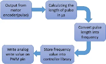
A. Frequency to PWM conversion using ARDUINO
IJIRT 142559
INTERNATIONAL JOURNAL OF INNOVATIVE RESEARCH IN TECHNOLOGY139
B. Real time Implementation setup
The setup for ongoing equipment demonstrate as above in fig. 13. Utilizing DSO and LabVIEW GUI, it's demonstrate the yield flags and some more. DSO used to demonstrate the produced PWM signal from controller. The both motors are associated together so it can be easy to watch speed synchronization between them.
Figure 13 Hardware setup C. Zero speed to positive negative speed
As shown in fig. 14 speed is varying from zero speed to positive negative rotation change. Set point changing between zeros to positive negative speed change. As shown in figure changing set point from zero to 36rpm speed, the first motor rotate at constant speed, in second motor chattering occurs to achieve the speed.
Figure 14 Real-time implementation result
Blue line is set point given to motor 1, speed of motor-1 is given as red line and the tracking speed of motor-2 shows in light blue color with chattering.
D. Set-point change from negative to positive speed track As show in fig. 15 the set point changing from 36 RPM, -24 RPM, 0 RPM, +-24 RPM and +36 RPM, the motors are tracking exactly track the speed, in this case tracking speed is varying around 0.9% at constant speed input.
Figure 15 Implementation result
to evolving set-point from counter clockwise expanding velocity to clockwise heading, its watch diminishing pace from quick to ease back and again ease back to quick. So set-point changing from counter clockwise to clockwise heading shows careful following in expanding stacking condition. The navy blue line shows set point, red line shows speed of motor 1 and lite blue with chattering shows tracked speed of motor-2.
Controller gives more action at slow speed, to get more tracking accuracy. At zero speed no chattering occurs to track the speed of motor.
E. From maximum negative to increasing speed
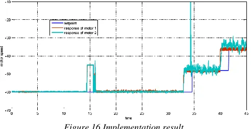
As shown in below fig. 16 at maximum speed at -60 RPM the both motors are rotating at zero error. But in case of high disturbance minor jerks shown inside the figure.
Most extreme pace rating of RMC-22xx servo motor is 60 RPM. So taking reaction at most extreme rate is exceptionally essential, greatest rate following is exceptionally unique case in light of the fact that at greatest rate limit auxiliary motor not able to expand pace to track the first motor. In this unique case the cross coupled control strategy lessen pace of motor 1 as indicated by input of motor 2.
Figure 16 Implementation result
For this situation cross-coupled controller make a move between both engines to take them into flawless synchronization at greatest rate following, the sliding mode controller produce control activity as per motor 2 input. The ordinary sliding mode controller may harm the motor drive when expand the velocity.
IX. CHATTERINGINHARDWAREIMPLEMENTATION
IJIRT 142559
INTERNATIONAL JOURNAL OF INNOVATIVE RESEARCH IN TECHNOLOGY140
genuine system, an exchanged controller has defects which restrict changing to a limited recurrence. The agent point then wavers inside of a neighborhood of the exchanging surface. This swaying, called chattering.
During control action, sliding mode control gives action according to set point achievement, in these case chattering occurs in between the set point tracking, due to this chattering around 0.92% error occurs in synchronization.
X. RESULTCOMPARISON
REFERENCES
[1] Shilong Wang; Liang Huang; Jie Zhou; Ling Kang, "A linear PI cross-coupled control for servo system of CNC gear hobbing machine," IEEE International Conference on Information and Automation (ICIA), 2010, pp.987-991.W.-K. Chen, Linear Networks and Systems. Belmont, CA: Wadsworth, 1993, pp. 123–135.
[2] Alessandro Pisano, Alejandro Davila, Leonid Fridman and Elio Usai, "Cascade Control of PM DC Drives Via Second-Order Sliding-Mode Technique," IEEE TRANSACTIONS ON INDUSTRIAL ELECTRONICS, VOL. 55, NO. 11, NOVEMBER 2008
[3] O-Shin Kwon, Seung-Hoe Choe and Hoon Heo, "A study on the dual-servo system using improved cross-coupling control method " ,10th International Conference on Environment and Electrical Engineering (EEEIC), pp. 1-4, 2011E. H. Miller, “A note on reflector arrays,” IEEE Trans. Antennas Propagat., to be published.
[4] Y Koren,”Variable-Gain Cross-Coupling Controller for Contouring,”
[5] Dong-Hee Lee and Jin-Woo Ahm,”Dual speed control scheme of servo drive system for a nonlinear Friction Compensation,” IEEE transection on power electronics, VOL. 23, NO.2, march-2008 Motorola Semiconductor Data Manual, Motorola Semiconductor Products Inc., Phoenix, AZ, 1989.
[6] Yoram Koren,”Cross-Coupled Biaxial Computer Control for Manufacturing System,” Journal of dynamic system, measurement and control, vol. 102/265, December1980 [7] Lingfei Xiao; Yue Zhu, “Sliding Mode Output Feedback
control based on tracking observer with disturbance estimator,” ISA Transection 53 (2014) 1061-1072 [8] Zhenxin He, “A Rotor Position/Speed Identification
Method of Permanent Magnet synchronization Motor for low Speed Operating Condition and Parameter Perturbation,” journal of information and computational science 2445-2457,2014
[9] Q.P. Ha;Q.H. Nguyen, “Fuzzy Sliding Mode Controllers with Applications,” IEEE Transaction on industrial electronics, VOL.48,NO.1,February 2001
[10] Alfonso Damiano, “Second Order Sliding Mode Control of DC Drives,” IEEE Transaction on induastrial electronics, VOL.51, NO.2, April, 2004