Datta Sainath Dwarampudi
11
Electronics and Communication Engineering, Mahatma Gandhi Institute of Technology, Hyderabad, Andhra Pradesh, India.
Abstract:- This paper aims at controlling a robot that is a tank like vehicle using a universal infrared remote
control. The infrared signal sent from the universal infrared remote control is received by IR receiver and decoded by the microcontroller PIC16F873A using an algorithm embedded in the microcontroller. The output from the microcontroller is fed to the motor driver which drives the left and right motors. The robot‟s motor control can be speed controlled by using PWM/PDM (Pulse Width Modulation/ Pulse Duration Modulation) technique.
Keywords:- Infrared, Universal Remote Control, PIC, Analysis, Construction, Speed Control, Robot.
I.
INTRODUCTION
A wirelessly controlled robot is the need of the hour. For many years the consumer electronics industry has been employing infrared remote controls for the control of televisions, VCR‟s and cable boxes. . The same concept is used for my project. The functionality of CIR (Consumer Infrared) is as broad as the consumer electronics that carry it. For instance, a television remote control can convey a “channel up” command to the television, while a computer might be able to surf the internet solely via CIR. The type, speed, bandwidth and power of the transmitted information depend on the particular CIR protocol employed.
This project can control the robot and move it at various speeds and in various directions. Its movement can be controlled by a universal remote control from a distance of ten to fifteen feet radius. The robot made from this project can move in forward and reverse direction with different speeds and it can turn left and right directions.
This paper gives an overview of the project completed during the period of internship at E.C.I.L. (Electronics Corporation of India Limited) at Hyderabad, India with technical details. The results are obtained and analysed. This report also deals with future works which can be persuaded as an advancement of the current. This robot has huge applications in industrial and home navigation. This robot is very useful during biological and chemical hazards to perform a task precisely and accurately.
II.
ANALYSIS
AND
CONSTRUCTION
This project can primarily be separated into four parts:
Sending and Receiving the infrared signal from the remote (Infrared Interface).
Decoding the infrared signals of a button of a remote control.
Establishing connection between microcontroller and motor driver.
Driving motor linked with motor driver using the algorithm embedded in the microcontroller.
A. Sending and receiving the infrared signal sent from the remote
Fig. 1: Block diagram for IS1U60 remote control IR sensor
Fig. 2: Infrared Sensor
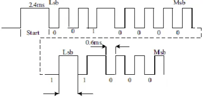
I have used a Sony remote control transmitter is used in this research. The Sony remote control is based on the Pulse-Width signal coding scheme. The code exists of 12 bits sent on a 40 KHz carrier wave. The code starts with a header of 2.4 millisecond (ms) or 4 times T, where T is 600 micro second (µs). The header is followed by 7 command bits and 5 address bits as show in Fig. 1. The address and commands exists of logical ones and zeros. A logical one is formed by a space of 600 µs and pulse of 600 µs. The space between 2 transmitted codes when a button is being pressed is 40 ms. The bits are transmitted least significant bits first. The total length of a bit-stream is always 45 ms.
An IR remote control (the transmitter) sends out pulses of infrared light that represent specific binary codes. These binary codes correspond to commands, such as Power On/Off and speed up. The IR receiver in the robot decodes the pulses of light into the binary data (ones and zeroes) that the device can understand. The microcontroller then carries out the corresponding command. The control codes are sent in serial format modulated to that 40 kHz carrier frequency (usually by turning the carrier on and off). There are many different manufacturers use different codes and different data rate for transmission. The data rate send is generally infra range of 100-2000 bps.
Fig. 3: Infrared signal from a Sony Remote Control
demodulator, which explains the presence of a long leading pulse in many of the protocols. This allows the receiver to stabilize its AGC circuit, prior to the reception of the bit-stream.
B. Decoding the IR signals for the buttons of a remote control
This is the next step of my project. Serial Infrared Control (SIRC) protocol is the name given to Sony‟s IR remote control. The 12 bit protocol is the most common format used with domestic products. I tried to map out the characteristic pulse and gap lengths that represent ones and zeros. By pressing the same button on the remote, write down the series of number read by the PIC16F873A running the program designed by me. The Output of the receiver is a binary bit-stream corresponding to the original modulation signal at the transmitter. Note that this signal is active low, so the “ones” in terms of the carrier signal appear as “zeros” at the demodulator. Each odd numbered entry is the duration of a burst of IR from the remote control. Each even numbered entry is the duration of a gap between bursts of infrared. The lengths of these gaps and bursts define ones and zeros. Their order will depend on which button is pressed. Once the characteristic lengths have been discovered for a one and a zero, an algorithm can then be created with a counter to translate the lengths into ones and zeros
Fig. 4: Sony Infrared Remote control Code format
Pressing the same button again will make us find the command length duration. This is necessary to determine if a button is being held down or a new command of the same type is being issued. Most remote controls repeat the command as long as the button is held down, the repetitions separated by a long dark time, usually on an even numbered transition. If no long even numbered counts can be found, consider that some commands can be longer than 64 transitions.
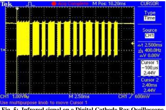
Fig. 5: Infrared signal on a Digital Cathode Ray Oscilloscope
Fig. 6: Infrared signal on a Digital Cathode Ray Oscilloscope(Magnified)
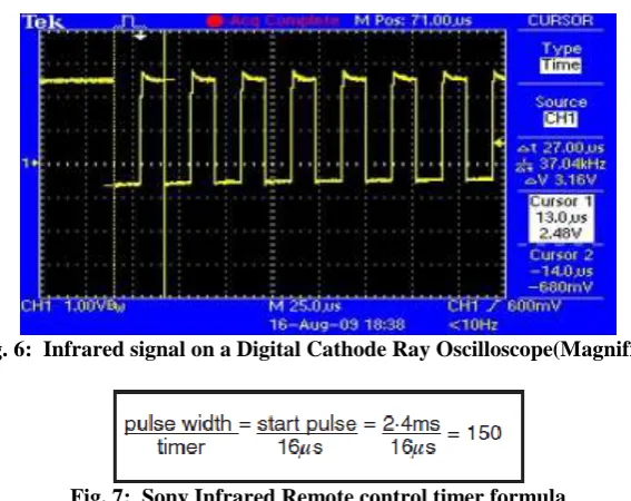
Fig. 7: Sony Infrared Remote control timer formula
The pulse length is measured by polling the falling edge of the waveform using the build in hardware timer, Timer 0. With 4 MHz crystal oscillator and pre scalar values of 16, the timer value is incremented every 16 µs and is read on every falling edge of the waveform. We can use the formula below to divide the expected pulse width by the timer.
Fig. 8: SIRC timer value for all pulse widths
Fig. 9: SIRC timing details
The program uses the timer value to determine the waveform. For example, if the value is between 90 and 150 then a logic 1 is assumed and if the value is between 50 and 90 the a logic 0 is assumed
We assign different keys for different functions as shown in the table below.
Table I: Modified Functions of Sony Remote Control Buttons
Remote’s Button function
key Original Function Modified Function
1 Channel 1 Start forward with
minimum speed
2 Channel 2 Stop
3 Channel 3 Speed decrease
4 Channel 4 Speed increase
5 Channel 5 Turn right
6 Channel 6 Turn left
C. Establishing the connection between microcontroller and motor driver
Fig. 10: PWM Output
Table II: CCP Mode-Timer Resource
CCP MODE Timer Resource
Capture Timer 1
Compare Timer 1
PWM Timer 2
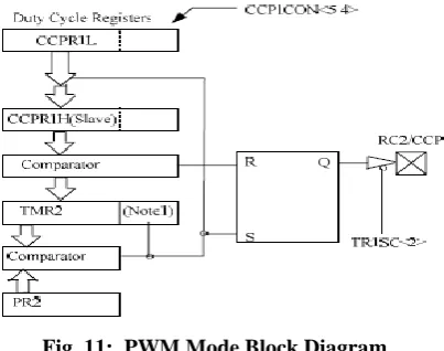
A Pulse Width Modulation output is a signal that has a time-base (period) and a time that the output stays high(duty cycle). The period is the duration after which the PWM rising edge repeats itself. The resolution of the PWM output is the granularity with which the duty cycle can be varied. The frequency of a PWM is simply the inverse of the period (1/period). Each CCP module can support one Pulse Width Modulation (PWM) output signal, with minimal software overhead. This PWM signal can attain a resolution of up to 10 bits, from the 8 bit Timer 2 module. This gives 1024 steps of variance from an 8 bit overflow counter. This gives a maximum accuracy of Tosc (50ns, when the device is operated at 20MHz). When the Timer 2 overflows (timer = period register), the value in the duty cycle registers (CCPRxL:CCPRx-CON<5:4>) is latched into the 10 bit slave latch. A new duty cycle value can be loaded into the duty cycle register(s) at any time, but is only latched into the slave latch. a new duty cycle value can be loaded into the duty cycle register(s) at anytime, but is only latched into the slave latch when Timer 2 = Timer 2 Period Register (PR 2). The period of Timer 2 (and PWM) is determined by the frequency of the device, the Timer 2 pre scaler value (1,4 or 16), and the Timer 2 Period Register. The following two equations show the calculation of the PWM period and duty cycle
Fig. 11: PWM Mode Block Diagram
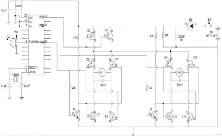
D. Driving motor linked with motor driver using the algorithm embedded in the microcontroller
driven off of an inverted copy of Side B Low. This arrangement means that the high and low transistors can never be on at the same time and it is required to generate two unique control signals per motor now. In order to run the motor forward, it is required to turn on transistors on the Side A High and the Side B Low. For reverse, it is required to turn on the Side B High and the Side A Low transistors. This circuit is powered by a 6 V battery via switch S2 and diode D2. D2 serves a dual purpose-first, to prevent reverse polarity, which could do considerable damage, and second, to drop the supply voltage to about 5.4 V, which is more suitable for the PIC16F873A. There are two identical H-Bridge motor drives, one for the left motor and one for the right. Pin 25 (RB4) and pin 23 (RB2) of the microcontroller is designated by the manufacturers for input or output. In this circuit, they are used for output only. Pin 25 is used for control the direction (forward or reverse) of the left hand motor, as seen from the rear of the robot. Pin 23 is used here to control the direction (forward or reverse) of the right hand motor. Direction control logic signals are from RB4 and RB2 of microcontroller switch two power MOSFETs H-Bridges to control the direction of the motors (forward or reverse). The two 100 (nF) capacitors across each motor. Pin 13 (RC2) of PIC16F873A can be used as a general purpose I/O pin or I/O pin for CCP1 module. In this circuit it is configured as CCP1 pin to produce PWM output. It is used to switch both of the motors on or off at the same time. It is also used to produce PWM for speed control of both motors. When it is „high‟, the motors are on: when it is “low‟ they are off. Since two logically inverted control signals are required for each side of an H-Bridge, a BJT transistor has been added in each H-Bridge motor drives circuit (Q1 for motor 1 and Q8 for motor 2). Actually transistors Q1 and Q8 are used as inverters so that when the “forward motion” MOSFETs Q3 and Q4 are disabled, the “reverse motion” MOSFETs Q6 and Q7 are activated. Note that neither pin 25 nor pin 23 will accomplish anything unless both motors are switch on first via pin 13 (RC2). Both pins 25 and 23 cause a wheel to rolls forward when it is high and backwards when it is “low”. Pins 13, 25, and 23 together may be used not only to make the robot drive forwards or reverse but also to turn right or left. Pin 13 (RC 2) activates both motors simultaneously via MOSFETs Q2 and Q5. These two MOSFETs are wired in parallel and these should work satisfactorily with a small heat sink for the small motors used here. Referring back to the drawing of the H-Bridge, it can be seen that if both transistors on one side of a bridge were turned on at the same time, it would have a direct short to ground. This problem is called shoot through current and it is a bigger problem than might be expected. FET‟s have a lot of capacitance 2000 pico Farad (pF) for the one used in this circuit on their gate leads, so it is difficult to switch them on or off quickly. This switching delay makes it very easy to have both FET‟s on for a short period of time each time. There is a transition from one FET conducting to the other. A lot of power can go through in that time and it will heat up transistors and cook them very quickly if allowed to happen. For this reason both motors are switched off first via pin 13, whenever one of the motor is need to change direction of rotation. After the required direction control commands are sent to the H-Bridges via pin RB4 and RB2. The two motors are switched on again via pin 13 and the previous PWM output is routed to the FET driver transistors Q2 and Q5.
Fig. 12: Similar H bridge circuit used in my project
III.
CONCLUSIONS
[1]. Bob Harbour, “Dual Motor Bidirectional Electronic Speed Control”, April 30,1999. http://www.circuits.Lab.com.
[2]. William G. Grimm, “Decoding Infrared Remote Controls Using a PIC 16C5X Microcontroller”, 1997. [3]. David De Vleeschauwer, “DAVschomepage”, http://user.pandora.be/davshomepage.
[4]. Microchip. “PIC16F873A Data Sheet” Microchip Technology Inc. May,2001.
[5]. Sanda Win, Tin Shein, Khin Maung Latt, “Design and Construction of PIC-based IR Remote Control Moving Robot”, World Academy of Science, Engineering and Technology Vol:2 2008.
[6]. Roger Thomas, “Remote Contrl IR Decoder” Everyday Practical Electronics, September, 2000. UK. http://www.microchip.com.
[7]. Mark Palmer, “Using the CCP Modules” Microchip Technology Inc. 1997. http://www.microchip.com. [8]. Ladyada, “IR Sensor”, adafruit learning system, http://learn.adafruit.com/ir-sensor/overview.
[9]. Consumer Infrared, Pulse-Width Modulation, Remote Control, Wikipedia.
[10]. William Cox, “Building an Infrared Remote Decoder”, May 29,2005, http://www.robotshop,com. [11]. “PIC 16F87XA, 28/40/44-Pin Enhanced Flash Microcontrollers”, MICROCHIP.
[12]. “PIC 16F87XA, 28/40/44-Pin Enhanced Flash Microcontrollers Data Sheet”, MICROCHIP. [13]. “PICmicro Mid-Range MCU Family Reference Manual”, MICROCHIP.
[14]. “Interfacing Interrupts with PIC16F877A”, Pantech Solutions. [15]. “H bridge motor driver circuit”, http://www.circuitstoday.com.