Design and Analysis on Hydraulic Press
Fixure for the Rear Wheel Hub Raceways
Fitment
Tadala Akhil Assistant Professor
Department Of Mechanical, Avanthi Engineering College , Tagarapuvalasa , Vizianagaram
Abdul Khurshid Assistant Professor
Department Of Mechanical, Avanthi Engineering College , Tagarapuvalasa , Vizianagaram
A.Manikanta
Department Of Mechanical, Avanthi Engineering College , Tagarapuvalasa , Vizianagaram
P.N.V Kalika Assistant Professor
Department Of Mechanical, Avanthi Engineering College , Tagarapuvalasa , Vizianagaram
Abstract:- In the content of the advanced technology engineers and scientists have visualized and conceptualized many designs and success of their designs and concepts is the materialization of their designs. In short it can be said that production and manufacturing units consummate the design process. Thus the Industry which gives shape and theoretical design is a very potential and influential element in the Technology development. The main objective of using Jigs and fixtures in an industry is to achieve the Interchangeable part concept, and these are mainly used where production of goods is on large scale. The basic elements in the design of Hydraulic press jig is component model, location , oreintation and Clamping has been done on the base plate. The scope of this project is to design a Hydraulic press jig For a component to hold the rear wheel hub of SXJ vehicle or LCV (light commercial vehicle) to fit The raceway or the collars into the wheel inner hub by using the hydraulic force . Design of the fixture Has been done on the CATIA V5 R19 3D modelling software and the design is imported and material Is added to the design and analysis has to be done on ANSYS workbench under static structural Module.
keywords: design , hydraulic press , raceway fitment, jigs , LCV( low commercial vehicle)
I. METHODOLOGY PROBLEM IDENTIFICATION
For Low Commercial Vehicles (L.C.V) the body parts are separately produced and shifted to the manufacturing unit in a bulk. The rear hub is also shifted to the M&M from ALFA chassis and accessories manufacturing unit near to the company. The rear hub has two parts i.e, inner part and outer cover part. The raceways are fitted to the inner part of the inner hub. During the transportation of the rear hub setup the raceways are being separated from the rear hub and again in the manufacturing unit the raceways or collars are fitted into the rear hub by some other means of loading on the raceways. During this type of process the work is getting slow and time gap is more. By this process the manufacturing of vehicle is getting slow down and the work is doubled for fixing two raceways . we need to reduce the time and we have to avoid the cost factor and transportation cost.
there are considerable steps to follow achieve the design and analysis has to be done.
x modeling according to the dimensions of rear hub and suitable fixture with constraints. x Force calculations for the raceway fitment
x Material required for the fixture design
Figure 1: inner and outer raceways
modeling according to the considered dimensions of rear hub and suitable fixture with constraints
The dimensions of the rear wheel hub has to be considered and the design of the internal hub is necessary for the analysis so the design has to created and 3D model has to be produced by using CATIA V5 . the rear internal hub has design considerations according to the raceways . the two raceways are designed separate to assemble the rear Hub and the collars or raceways. The collars are used to avoid the frictional contact between the axle and hub by adding bearings between them. the bearing s are to be tightly fixed to the collar to it can resist to avoid the dismandling of the bearing from the hub. For fitting the collars the fits calculations to be done.
Figure 2: 3D modeling of hub design Figure 3: rear wheel hub
Figure 4: disassembled inner and outer hub design Figure 5: inner hub design
equipment like locating pins and the guide bush and other allignments linearly under the contraints defined and set for the assembly
Design Of The Guide Bush
Guide bush is the centre for the fixture and the inner raceway will rest on the design of the guide bush and hold the pressure applied on the fixture to be conditioned and designed suitable for cyclic loading
the centre hole for the guide bush is designed to hold the JIG i.e Pressing Dolley and to restrict the motion of other two axis and to hold the fixture and the internal part of the hub together. The holes are alligned to the holes of the baseplate and fixed tightly with the allen screws.
Figure 6: 3D model of base plate Figure 7: guide bush Design Of The Locating Pin
the locating pin are the pillar like structure allign in a circular formation 120 degrees apart to hold the external hub of the wheel and to restirct the motion of the hub while loading is applied on the hub to fit the collars into it. the sub deisgn of the fixture locating pin is the suspension springs. the suspension springs mainly used for the absorbing the sudden loads by compression and expansion of the spring while loading conditions takes place the loading is done frequently so the spring constant (k) has to be calculated by considering the industrial design conditions and the loading theory.
the locating pins are supported to the spring without deviating side ward while compression takes place and to not deviate the other directions.
Figure 8: locating pin Figure 9: spring constant variations
the spring is attached to the locating pin by using allen screw which through the baseplate itself to fix it firm the top end of the spring is fixed to the SLIDER blocks to give the Base to the wheel hub and rest on the slider blocks top and give supports to the hub while loading condition the slider also reciprocates while the loading conditions takes place. the three locating pins will distributed all along the circular crown 120 degrees apart and the load applied on the fixture is equally distributed all along the three loacating pins and the supporting springs absorb the cyclic loads and the springs are used to lift the hub after loading and fitting is done. by the force applying or the distributed force all along the spring is distributed an resist to bend and the K constant of spring is calculated and the suitable spring is designed and the material selection to be done.
Assembly Of The Fixture Components
the base plate by the below
Figure 10: locating pin Figure 11: slider Figure 12: supporting spring
Figure 13: assembling of base plate and the guide bush Figure 14: assmbled of guide bush to base plate with allen screws
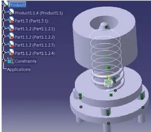
Figure 17: fully assembled fixture Figure 18: assembling and placing the hub setup on the fixture Design Of Pressing Dolley
Pressing dolley is designed and the length should be decided by the dimensions of the guide bush and the hole in the guide bush. The raceaways are to be designed .there are two raceways i.e inner raceway and outer raceway
Figure 19: pressing dolley Figure 20: inner raceway
Figure 23: Fitment and working of the Fixture
FORCE CALCULATIONS ON THE RACEWAY FITMENT AND THE DISTRIBUTION OF FORCE Force calculation for inner raceway
Inner diameter of the Hub :95 (-0.038 ,-0.073) Min ID of Hub=---94.927mm MMC
Max ID of hub=---94.962mm LMC Outer diameter of raceway =95 (0.03,0.087)
Max dia of raceway=---95.087mm MMC Min dia of raceway =---95.03mm LMC
į 00&RIUDFHZD\- MMC of hub :0.16mm ---0.00629 inch Considering this fit is interferance.
Dia of raceway to be pressed into hub D =95.00mm ---3.7392 inch Length of bore L=30 mm---1.17 inch
P= constant factor for dia raceway=122/2
calculating the force required to press the raceway into hub is: F=DX3.14XL;į;3 Therefore F=3.7392x122/2x1.17x0.00692x3.14
F=5.270 ton
Force calculation for outer raceway Inner diameter of the Hub : 90 (-0.038 ,-0.073) Min ID of Hub=---89.927mm MMC
Max ID of hub=---89.962mm LMC Outer diameter of raceway =90 (0.03,0.087)
Max dia of raceway=---90.087mm MMC Min dia of raceway =---90.03mm LMC
į 00&RIUDFHZD\- MMC of hub :0.16mm ---0.00629 inch Considering this fit is interferance.
Dia of raceway to be pressed into hub D =90.00mm ---3.5424 inch Length of bore L=25 mm---0.984 inch
P= constant factor for dia raceway=131/2
Therefore F=3.5424x131/2x0.984x0.00692x3.14 F=4.9610 ton
total force required for the inner and outer raceway fitment is F F= F1+F2
F1= 5.2270 tons F2= 4.9610 tons F= 10.188 tons
pressure on the area considered on the guide bush
N/m2
P= 100796.31/0.001005585 P= 10,02,36,489.207 N/m2
Force Acting on the slider and spring by the self weight of hub
• Total weight of the hub setup = 24 kgs = 235 N • The area of slider face = 0.003613 m2
• Total pressure acting on the slider faces = 126850 N/m2 total no of sliders = 3
The final Pressure acting on each slider face = 47947.925 N/m2
Table 1: components and respective materials
s.no Parts named Material required Quantity
1 Base plate Mild steel 1
2 slider En8 3
3 Guide bush 16MnCr5 1
4 Locating pin En8 3
5 spring Spring steel C85 3
6 Pressing dolly En8 1
7 Allen screws M6 , M5 12, 4
Table 2: mechanical properties of the materials s.no material Density
Kg/m3 Young’s modulus Mpa
Poison’s
ratio Ultimate yield Strength Mpa
Ultimate tensile Strength Mpa
1 En8 7880 210 0.285 245 510
2 C85 7900 215 0.3 275 450
3 16MnCr5 7850 206 0.3 588 786
STRUCTURAL ANALYSIS ON FIXTURE COMPONENTS
Figure 24: load application of guide bush Figure 25: equivalent stresses on guide bush Figure 26: equivalent stresses of slider RESULTS
components Von-mises
stresses(Pa)
Deformation(m) Ulimate tensile
stresses( MPa)
Guide Bush 1.21421 x 10⁸ 1.0128 x 10⁻⁵ 786
Supporting Spring 1.3146 x 10⁷ 9.3367 x 10⁻⁶ 450
Slider 3.4317 x 10⁷ 9.7451 x 10⁻⁷ 510
Whole components
together fixture 1.4651 x 10
9 0.000516544 786 ( highly stressed
region material cond.
II. RESULTS AND DISCUSSION
DISCUSSION
By the above analysis on the fixture with and without hydraulic loading the equivalent stresses and the deformation can be analyzed on each and every components individually and the combined analysis of the fixture is also be determine and compare the von-misses stresses to the ultimate tensile strength and if the distortion energy theory failures then the fixture is not a proper condition we need to design in a new way. the comparison results of the design and analysis by distortion theory are in under the safety conditions so the design is in the appropriate working conditions.cyclic loading is also allowed under this analysis
RESULTS
Figure 27: equivalent stresses on hydraulic loading CONCLUSION
we can reduce the transportation cost and the assembly cost and we can have the self assembly system in the assembly area itself under proper conditions and loadings.
For Low Commercial Vehicles (L.C.V) the body parts are separately produced and shifted to the manufacturing unit in a bulk. The rear hub has two parts i.e, inner part and outer cover part. the cost factor is main problem in any industry and the repetition of work on same component will delay the processing time and assembled components be reduced that effects the production and delay the process to avoid all these effects we need to effectively install this fixture in the assembly unit . the drawings are attached to the file as designed above.
REFERENCES
[1] Luis E. Izquierdo1, S. Jack Hu1, Hao Du1, Ran Jin2, Haeseong Jee3 and Jianjun Shi2 “Robust Fixture Layout Design For A Product Family Assembled In A Multistages Reconfigurable Line “Department of Mechanical Engineering. The University of Michigan 2350 Hayward Street, Ann Arbor, MI 48109
[2] Yu Michael Wang and Diana Pelinescu “OPTIMAL FIXTURE LAYOUT DESIGN IN A DISCRETE DOMAIN FOR 3D WORK PIECES” 2001 IEEE International Conference on Robotics & Automation Seoul, Korea • May 21-26, 2001
[3] http.www.wikipedia.org/wiki/ Road_roller
[4] Siddesha K, Dr. D. Ramegowda “Design And Analysis Of Welding Fixture For the footrest stand component”in the International journal of engineering research & Technology ISSN: 2278-0181, Vol. 4 Issue 04,Pg-no-995-998, April-2015