e-ISSN: 2278-067X, p-ISSN: 2278-800X, www.ijerd.com
Volume 11, Issue 10 (October 2015), PP.28-43
Harmonic Optimization of Multilevel Inverter
Nitesh Kumar Gupta, Dr.R. Mahanty
Integrated Dual Degree (Power Electronics) Student, Department of Electrical Engineering Indian Institute of Technology, (Banaras Hindu University), Varanasi, India Professor, Department of Electrical Engineering, Indian Institute of Technology,
(Banaras Hindu University),Varanasi, India
Abstract:-In present work, optimization techniques genetic algorithm (GA) and particle swarm optimization (PSO) are used to compute switching angles for the cascaded multilevel inverter for selective harmonic elimination and the results are compared. Switching angles obtained from PSO produced better output with less harmonic content. Due to better performance PSO results are used further to obtain training set for Artificial Neural Network (ANN). Hence implementation of ANN for the elimination of low order harmonics is presented. Output voltage for nine level inverter is obtained for both single phase and three phase Cascaded Multilevel Inverter (CMLI). Switching angles are calculated through GA and PSO for various modulation indices and for minimum Total Harmonic Distortion (THD). Simulation results are presented using MATLAB and m file program. Through ANN real time implementation is possible with significantly reduced lower harmonics and improved performance.
Keywords:-artificial neural network, fitness value, modulation index, multilevel inverter, genetic algorithm, particle swarm optimization, selective harmonic elimination, total harmonic distortion.
I.
INTRODUCTION
High voltage transmission has become very important concern for the power electronic industries which needs to be handled at both transmission and distribution levels. Conventional two-level inverters cannot be used for this purpose since the semiconductor devices must be connected in series to obtain the required high-voltage which can cause the failure of the device. This high voltage can be achieved by summing the outputs of several two-level converters with transformers or inductors, or by more complex topologies such as multilevel inverters [1]–[3]. Multilevel inverters include an array of power semiconductors and voltage sources, the output of which generate voltage with stepped waveforms. The commutation of the switches permit the addition of the input voltages to obtain high voltage at output, while the power semiconductors withstand only reduced voltages [1]-[2].
H bridge topology of the multilevel inverter is particularly attractive because of their modularity and simplicity of control [5]. The output voltage obtained from a multilevel inverter contains harmonics which has to be eliminated for better performance. Harmonic content can be reduced with proper switching angles which can be obtained using several methods. Methods like Resultant Theory and Newton Raphson involves nonlinear transcendental equations which are complex to solve and requires initial guess [4]-[8].
In this paper GA and PSO are used to obtain switching angles to minimize THD. These techniques are suitable for higher level of multilevel inverters where other conventional methods fail to compute the switching angles due to more computations [8]-[9]. These schemes are implemented in such a way that all possible solutions are obtained without assuming any proper initial solution and hence control over magnitude of output voltage for a multilevel inverter is achieved [11]-[13].The cost function used is a minimization function which, with the help of MATLAB program, provides the angles for optimized switching.
II.
CASCADED
MULTILEVEL
INVERTERS
Cascaded multi-level inverter synthesizes a desired voltage from several independent sources of dc voltages, which may be obtained from batteries, fuel cells, or solar cells. This configuration has recently become very popular in ac power supply and adjustable speed drive applications [6]-[8]. This inverter can avoid extra clamping diodes or voltage balancing capacitors [6]. A single-phase m-level configuration of such an inverter is shown in Figure 1. Each DC source is associated with a single-phase full-bridge inverter. The ac terminal voltages of different level inverters are connected in series. By different combinations of the four switches, S1-S4, each inverter level can generate three different voltage outputs, +Vdc, -Vdc, and zero. The ac output of each of the different level of full-bridge inverters are connected in series such that the synthesized voltage waveform is the sum of the inverter outputs. The number of output phase voltage levels is defined by m = 2s+1, where s is the number of dc sources [3].
Figure 1. Single-phase structure of a multilevel cascaded inverter [3]
Figure 2. A general three-phase Wye-configuration cascaded-inverters based inverter [3].
Appropriate switching angles result in a sinusoidal output waveform. Switching angles α1, α2, α3, α4 shown in figure have to be selected appropriately to eliminate the certain lower order harmonics. Three phase configuration can be formed by connecting three numbers of these inverters in Y or Δ [1] as shown in figure 2. The Fourier series of the quarter-wave symmetric s H-bridge cell multilevel waveform is written as follows:
Vout 𝜔𝑡 = [
4𝐸
𝑛𝜋 ∞
𝑛=1 𝑠𝑖=1cos(𝑛𝛼𝑘)]sin(𝑛𝜔𝑡) (1)
Where,
αk is the switching angles, which must satisfy the following condition α1, α2,…, αs < π/2.
s is the number of H-bridge cells. n is odd harmonic order and E is the amplitude of dc voltages.
The harmonic components in the waveform can be described as follows: 1) The amplitude of dc component equals zero.
h1= 4𝐸
𝜋 cos(𝛼𝑘)
𝑠
𝑖=1 (2)
hn= 4𝐸
𝑛𝜋 cos(𝑛𝛼𝑘)
𝑠
𝑖=1 (3)
3) The amplitude of all even harmonics equals zero.
Thus, only the odd harmonics in the quarter-wave symmetric multilevel waveform need to be eliminated. The switching angles of the waveform will be adjusted to get the lowest output voltage THD.
THD = ∞ ℎ𝑛2
𝑛 =2
h1 (4)
From the waveform shown in Figure 1, s switching angles, namely α1,α2,…αS, need to be known. Mathematically, s equations obtained from (1) are set up. These are:
cos(α1)+ cos(α2)+ cos(α3)+cos(α4) = s*M (5)
cos(5α1)+ cos(5α2)+ cos(5α3) +cos(5α4) = 0 (6)
cos(7α1)+ cos(7α2)+ cos(7α3) +cos(7α4) = 0 (7)
cos(11α1)+ cos(11α2)+ cos(11α3) +cos(11α4) = 0 (8)
From above equations (5) to (8) it can be seen that for a nine level CMLI the number of variables is four therefore equations required for a unique solution are four. Here, the harmonics which can be taken into account are 5th, 7th and 11th. Hence the number of harmonics which can be eliminated selectively is ‘s-1’. Here ‘s’ is no. of dc sources or no. of full bridge cells in CMLI. Triplen harmonics are eliminated in three-phase balanced system.
` These nonlinear equations (5) to (8) have multiple solutions. The main problem is of discontinuity at certain points where no set of solution is available. This limitation is addressed in methods presented in this paper i.e. GA and PSO.
III.
GENETIC
ALGORITHM
(GA)
Genetic algorithm is a computational model that is used to solve optimization problems. It imitates biological evolution by using genetic operators like reproduction, crossover, mutation, etc. To minimize a function f(x1, x2, x3…., xk), using GA each xi is coded as a binary or floating-point string. The set of {x1, x2,….,xk} is called a chromosome and xi are called genes.
Below are the steps for formulating a GA problem: 1- Select binary or floating point strings.
2- Find the number of variables specific to the problem which is equivalent to number of genes in a chromosome. In this paper, the number of variables is the number of H-bridges, which is the number of switching angles in a cascaded multilevel inverter. A nine bridge multilevel inverter will have four switching angles, i.e. {α1, α2, α3, α4}.
3- Set a population size and initialize the population. Higher population might increase the rate of convergence but also increases the execution time. The population is initialized with random angles between 0 and 90 degrees. Quarter-wave symmetry of the output voltage waveform is taken into consideration for selecting angles.
4- A cost function is used to evaluate fitness of each chromosome. The objective is to minimize harmonics; therefore the cost function has to be related to these harmonics. Since 5th, 7th and 11th harmonics at the output of a 9-level inverter have to be minimized, the cost function [13], f can be selected as sum of these three harmonics normalized to the fundamental,
f(α1,α2,α3,α4 )=100*[|M-|𝑉1| |𝑠𝑉𝑑𝑐 ||+
𝑉5 + 𝑉7 + 𝑉11 +⋯..+|𝑉3𝑠−2 𝑜𝑟 3𝑠−1|
𝑠𝑉𝑑𝑐 ] (9)
Where, αi are the switching angles and Vn are the nth order voltage harmonics.
A multilevel output voltage is created for each chromosome using corresponding switching angles and harmonics magnitude is calculated using FFT in MATLAB. The fitness value, FV is calculated for each chromosome using equation (9). Switching angle set producing the max FV is the best solution of the first iteration.
GA is set to run for a certain number of iterations to find final solution. GA can converge to a solution in the iterations much before maximum number of iterations is completed. In this work, the iterations have been stopped when the cost function goes below 1 in which case the sum of selected harmonics is negligible as compared to the fundamental. MATLAB GA Optimization Toolbox is used which has to be run as many number of times as the number of modulation indices to get individual solution [9].
IV.
PARTICLE
SWARM
OPTIMIZATION
(PSO)
shares many similarities with Genetic Algorithms (GA) [14]. The system is initialized with a population of random solutions. Optimization is achieved through searching and subsequent update of variables for next generation. Unlike GA, PSO has no evolution operators such as crossover and mutation. In PSO potential solutions are called particles which fly through the problem space by following the current optimum particles. Each individual is represented by a vector in multidimensional search space. This vector which determines the next movement of the particle is called velocity vector. Each particle updates its velocity based on current velocity and the best position it has explored so far; and also based on the global best position explored by whole population [13-15]. In past several years, PSO has been successfully applied in many research and application areas [15]. It is demonstrated that PSO gets better results in a faster and cheaper way compared with other methods [16],[17]. Another reason that PSO is attractive is that there are few parameters to adjust.
Formulating the problem:
Let θi = [θi1, θid…, θis] be a trial vector representing the ith particle of the swarm to be evolved. The elements of θi are the solutions of the harmonic minimization problem, and the dth element is corresponding to the dth switching angle of the inverter. The steps to formulate the problem and applying PSO are as follows:
1) Get the data for the system.
At the first step, the required parameters of the algorithm such as population size M, maximum iteration number itermax, etc. are determined and the iteration counter is set to iter = 1.
2) Generate the initial conditions of each particle.
Each particle in the population is randomly initialized between 0 and π/2; similarly, the velocity vector of each particle has to be generated randomly.
3) Evaluate the particles.
Each particle is evaluated using the fitness function of the harmonic minimization problem. The switching angles θ1, θ2 . . . , θs in a multilevel inverter for the output waveform can be calculated such that odd and non-triple low-order harmonics up to the 3s − 2th order when s is odd and up to the 3s − 1th order when s is even can be eliminated from the output phase voltage of the inverter to minimize the cost function.
4) Update the personal best position of the particles.
If the current position of the ith particle is better than its previous personal best position, replace personal best position with the current position. If the best position of the personal bests of the particles is better than the position of the global best, replace global best position with the best position of the personal bests.
5) Update the velocity and position vectors. It is done using governing equations in PSO algorithm. 6) Termination criteria.
If the iteration counter iter reaches itermax, stop; else, increase the iteration counter iter = iter + 1 and go back to step 3.
Fitness function used is same as GA. All the possible set of solutions is obtained for the angles θ1 to θs. The angles obtained are such that the values of low order harmonics are lowest or within the permissible limit.
V.
ARTIFICIALNEURALNETWORK(ANN)Artificial neural networks are used in many applications in engineering, such as pattern recognition, control and classification, and others [18- 20]. One of the main factors for choosing this technique is its generalization ability in nonlinear problems that are complex in nature and calculation intensive [21]. Artificial neural networks are computational models that were inspired by biological neurons [22]. They use a series of nodes with interconnections where mathematical functions are applied to do an input/output mapping. Hence information contained in a lookup table can be stored in an ANN. The challenge is to know how many neurons will be needed to train an ANN for a specific application. This will be dependent on complexity of the input/output relation, number of inputs and number of outputs and requires some trial and error in initial until a suitable ANN is found [23-24].
The network model is integrated with nine level CMLI to generate the switching angles in real time. This system has ability to update the angles in real time at speeds higher than the line frequency (50 Hertz), but the angle update is done at the end of a cycle to avoid even harmonics. The simulations are carried out for nine-level CMLI for both single phase and three phase. Initial solution is created using PSO and then training is done in MATLAB. The change in switching angles is done by ANN during the simulation upon change of input voltage to maintain the fundamental at desired value. It is observed that ANN output comes close to the desired output and the THD is minimized.
Performance is measured by calculating the mean squared error (MSE) as shown in Equation (10).
e =1
𝑝 𝑦
𝑖− 𝑑𝑖 2 𝑝
𝑖=1 (10)
Where,
p: number of training data entries y: ANN output vector
d: desired output vector
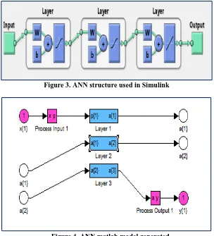
Figure 3. ANN structure used in Simulink
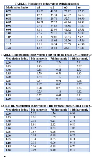
Figure 4. ANN matlab model generated
Here, the 5th, 7th and 11th harmonics are minimized using the angles provided by the ANN. The individual voltage harmonics are less than one percent of fundamental.
VI.
SIMULATION
RESULTS
A. GA Result
TABLE I. Modulation index versus switching angles Modulation Index α1 α2 α3 α4
0.70 15.23 41.93 73.12 87.55
0.75 12.23 35.34 68.22 86.12
0.80 10.44 29.71 52.71 86.90
0.85 10.21 27.22 48.14 80.91
0.90 9.48 24.63 44.56 71.83
0.95 8.11 23.98 41.92 65.55
1.00 7.56 22.15 37.28 61.87
1.05 6.34 20.08 32.33 53.23
1.10 4.46 18.04 31.50 45.86
1.15 2.11 16.34 26.59 41.90
1.20 1.87 15.84 24.31 41.41
TABLE II.Modulation Index versus THD for single-phase CMLI using GA Modulation Index 5th harmonic 7th harmonic 11th harmonic
0.70 2.12 2.74 2.91
0.75 1.45 1.19 2.22
0.80 0.18 0.21 2.73
0.85 1.79 0.58 1.43
0.90 1.34 1.12 1.21
0.95 0.87 0.91 0.98
1.00 1.87 0.03 0.37
1.05 0.98 0.23 0.34
1.10 0.25 1.19 0.12
1.15 0.32 0.41 0.11
1.20 0.11 0.18 0.22
TABLE III. Modulation Index versus THD for three-phase CMLI using GA Modulation Index 5th harmonic 7th harmonic 11th harmonic
0.70 2.12 1.76 0.98
0.75 2.01 1.09 1.11
0.80 0.18 0.21 2.73
0.85 1.91 2.12 0.86
0.90 1.12 0.54 1.05
0.95 0.87 0.26 0.98
1.00 0.65 0.98 0.23
1.05 0.34 0.65 0.11
1.10 0.18 0.06 0.19
1.15 0.16 0.18 0.76
1.20 0.09 0.10 0.12
B. PSO Result
TABLEIV. Modulation index versus switching angles Modulation Index α1 α2 α3 α4
0.70 15.01 40.55 73.23 86.92
0.75 12.02 34.22 67.55 85.32
0.80 10.31 29.13 51.05 86.15
0.85 10.02 26.43 48.84 79.63
0.90 9.23 24.21 45.55 70.18
0.95 8.04 23.01 40.97 64.29
1.00 7.32 21.87 36.46 60.83
1.05 6.15 19.83 33.33 53.45
1.10 4.45 17.32 32.61 44.06
1.15 2.54 16.44 26.18 42.22
1.20 1.76 15.03 24.33 40.54
TABLE V. Modulation Index versus THD for single-phase CMLI using PSO Modulation Index 5th harmonic 7th harmonic 11th harmonic
0.70 2.32 2.13 2.04
0.75 1.16 1.64 1.01
0.80 1.71 0.66 0.87
0.85 1.01 0.35 0.44
0.90 0.95 1.11 0.72
0.95 0.76 0.76 0.43
1.00 0.69 0.77 1.32
1.05 1.55 0.24 0.23
1.10 1.24 0.11 0.53
1.15 0.52 0.28 0.05
1.20 0.33 0.12 0.09
TABLE VI. Modulation Index versus THD for single-phase CMLI using PSO Modulation Index 5th harmonic 7th harmonic 11th harmonic
0.70 1.82 1.63 0.99
0.75 1.56 1.14 1.08
0.80 1.11 1.01 0.87
0.85 0.95 1.13 0.57
0.90 1.05 0.56 1.02
0.95 0.72 0.24 0.72
1.00 1.01 0.99 0.25
1.05 0.62 0.74 0.54
1.10 0.29 0.22 0.42
1.15 0.13 0.10 0.61
1.20 0.06 0.11 0.22
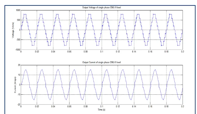
Nine level single phase CMLI
Figure 5. Output voltage and output current of single phase nine level CMLI
For switching angles calculated from GA
Figure 6. Harmonic spectrum of output voltage of single phase CMLI at M.I. = 0.95
For switching angles calculated from PSO
Figure 8. Harmonic spectrum of output voltage of single phase CMLI at M.I. = 0.95
Figure 9. Harmonic spectrum of output current of single phase CMLI at M.I. = 0.95
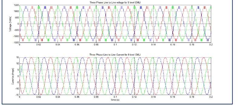
Nine level three phase CMLI
Figure 10 shows the line to line output voltage and output current of three phase nine level CMLI. It consists of sixteen switching devices with four separate DC sources per phase.
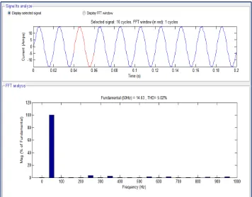
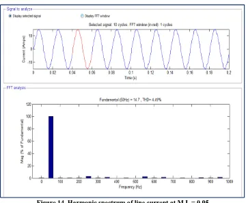
The harmonic spectrum of line voltage of CMLI for phase A is shown in Figure 11 and 13 for switching angles calculated from GA and PSO respectively. The harmonic spectrum of line current of CMLI for phase A is shown in Figure 12 and 14 for switching angles calculated from GA and PSO respectively. The THD for line voltage is 9.76% for GA and 8.43 % for PSO. It is evident from this figure that the selected 5th, 7th and 11th harmonics are significantly reduced. The THD for line current is 5.02% for GA and 4.49 % for PSO.
• For switching angles calculated from GA
Figure 11. Harmonic spectrum of line voltage at M.I. = 0.95
For switching angles calculated from PSO
Figure 13. Harmonic spectrum of line voltage at M.I. = 0.95
Figure 14. Harmonic spectrum of line current at M.I. = 0.95
Comparison between results obtained through GA and PSO:
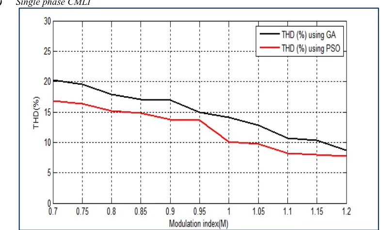
(a) Single phase CMLI
Figure 15. Total harmonic distortion versus modulation index for single phase CMLI
(b) Three phase CMLI
Figure 16. Total harmonic distortion versus modulation index for three phase CMLI
C. ANN Result
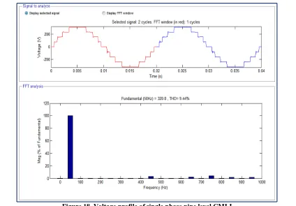
Figure 17 shows that after one cycle of the output waveform angles are adapted to the new condition. The ANN placed a small increment in the angles to adapt to the new condition. Due to the low computation time required by the neural network, the angles are always available long before a cycle ends, but they are updated only at the end of the cycle.
Figure 17. Output Voltage and current waveform of nine level CMLI
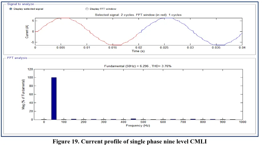
The change in switching angles is done by ANN during the simulation upon change of input voltage to maintain the fundamental close to 230 volts. Voltage THD is 9.44% of fundamental for single phase CMLI as shown in the figure 18. This includes triplen harmonics which will be cancelled out in the line to line voltage for three phase CMLI. THD is now reduced to 5.97% of fundamental for three phase as shown in the figure 20. The THD of the current waveform is 3.76% for single phase as shown in figure 19 and 2.95% for three phase as shown in figure 21 which is in the acceptable range.
Figure 19. Current profile of single phase nine level CMLI
Figure 20. Voltage profile of three phase nine level CMLI
VII.
CONCLUSIONS
Firstly the comparison between results obtained from GA and PSO algorithms has been made for nine level CMLI for both single phase and three phase. It is observed that PSO reduces THD more as compare to GA due to its better convergence. The harmonics eliminated with the help of these techniques are lower order harmonics and high order harmonics can be further reduced with the help of appropriate filter. The main advantages of these algorithms are that an output with acceptable range of harmonics can be obtained without use of a bulky filter and hence the overall cost of the system can be reduced. Then an approach for real time computation of switching angles using artificial neural networks is presented. The solutions are found off line using particle swarm optimization to obtain a data set to use during the training process of the neural network. PSO is also used so as to explore the advantages of approximate solutions. The trained neural network was simulated in MATLAB for online real-time determination of the angles. Output angles returned by ANN may not provide a satisfactory result, or harmonic elimination, at some points as it generalizes; however, a fast result can be obtained and more angles can be easily added to provide a better output waveform. Parallel networks can be used to accomplish better performance. The angles are updated at same frequency of the fundamental output voltage due to the low computation time required for the neural network.
REFERENCES
[1]. J. Rodriguez, J. Lai, F. Z. Peng, ―Multilevel inverters: a survey of topologies, control and applications,‖ IEEE Transactions on Industrial Electronics, vol. 49, no. 4, pp. 724-738, Aug. 2002. [2]. A. Pandey, B. Singh, B. N. Singh, A. Chandra, K. Al-Haddad, D. P. Kothari, ―A review of multilevel
power converters,‖ Institute of Engineers Journal (India) , pp. 220-231, vol. 86, March 2006.
[3]. S. Kouro,M. Malinowski, K. Gopakumar, J. Pou, L. G. Franquelo, B. Wu, J.Rodriguez, M. A. Perez, J. I. Leon, ―Recent advances and industrial applications of multilevel converters, ‖ IEEE Transactions on Industrial Electronics, vol. 57, no. 8, pp. 2553-2580, Aug. 2010.
[4]. R. Rangarajan, F. E. Villaseca, ―A switching scheme for multilevel converters with non-equal DC sources,‖ 39th North American Power Symposium, pp. 308-313, Sept. 2007.
[5]. J. N. Chiasson, L. M. Tolbert, K. J. McKenzie, Z. Du, ―A unified approach to solving the harmonic elimination equations in multilevel converters,‖ IEEE Transactions on Power Electronics, vol. 19, no. 2, pp. 478-490, Mar. 2004.
[6]. J. N. Chiasson, L. M. Tolbert, K. J. McKenzie, Z. Du, ―Elimination of harmonics in a multilevel converter using the theory of symmetric polynomials and resultants,‖ IEEE Transactions on Control Systems Technology, vol. 13, no. 2, pp. 216-223, March 2005.
[7]. D. Ahmadi, Jin Wang, ―Selective harmonic elimination for multilevel inverters with unbalanced DC inputs,‖ IEEE Vehicle Power and Propulsion Conference, pp. 773-778, Sept. 2009.
[8]. T. Tang, J. Han, X. Tan, ―Selective harmonic elimination for a cascade multilevel inverter,‖ IEEE International Symposium on Industrial Electronics, pp. 977-981, July 2006.
[9]. J. R. Wells, B. M. Nee, P. L. Chapman, P. T. Krein, ―Selective harmonic control: a general problem formulation and selected solutions,‖ IEEE Transactions on Power Electronics, vol. 20, no. 6, pp. 1337-1345, Nov. 2005.
[10]. M. S. A. Dahidah, V. G. Agelidis, ―Selective harmonic elimination PWM control for cascaded multilevel voltage source converters: A generalized formula,‖ IEEE Transactions on Power Electronics, vol. 23, no. 4, pp. 1620-1630, July 2008.
[11]. B. Ozpineci, L. M. Tolbert, J. N. Chiasson, ―Harmonic optimization of multilevel converters using genetic algorithms,‖ IEEE Power Electronics Letters, vol. 3, no. 3, pp. 92-95, Sept. 2005.
[12]. K.F. Man, K.S. Tang, S. Kwong, ―Genetic algorithms: concepts and applications in engineering design],‖ IEEE Transactions on Industrial Electronics, vol.43, no.5, pp.519-534, Oct 1996.
[13]. C. R. Houck, J. A. Joines and M. G. Kay, ―A genetic algorithm for function optimization: A Matlab implementation,‖ Technical Report NCSU-IE-TR-95-09, North Carolina State University, Raleigh, NC (1995).
[14]. H. Taghizadeh and M. Tarafdar Hagh, ―Harmonic Elimination of Cascade Multilevel Inverters with Nonequal DC Sources Using Particle Swarm Optimization‖ IEEE Transactions on Industrial Electronics, vol. 57, no. 11, November 2010.
[15]. J. Kennedy and R. Eberhart, ―Particle swarm optimization,‖ in Proc. IEEE Int. Conf. Neural Netw., 1995, vol. 4, pp. 1942–1948.
[17]. Y. Liu, H. Hong, A. Q. Huang, ―Real-time calculation of switching angles minimizing THD for multilevel inverters with step modulation,‖ IEEE Transaction on Industrial Electronics, vol. 56, no. 2, pp. 285-293, Feb. 2009.
[18]. F. J. T. Filho, L. M. Tolbert, Y. Cao, B. Ozpineci, ―Real time selective harmonic minimization for multilevel inverters connected to solar panels using artificial neural network angle generation,‖ IEEE Energy Conversion Congress and Exposition, pp. 594-598, Sept. 2010.
[19]. R. Aggarwal, Y. Song, ―Artificial neural networks in power systems II: types of artificial neural networks,‖ Power Engineering Journal, vol. 12, no. 1, pp. 41-47, Feb. 1998.
[20]. R. Aggarwal, Y. Song, ―Artificial neural networks in power systems I: general introduction to neural computing,‖ Power Engineering Journal, vol. 11, no. 3, pp. 129-134, Jun. 1997.
[21]. H. C. Lin, ―Intelligent neural network-based fast power system harmonic detection,‖ IEEE Transactions on Industrial Electronics, vol.54, no.1, pp.43-52, Feb. 2007.
[22]. N. Mohan, T. M. Undeland, and W. P. Robbins, Power Electronics: Converters, Applications and Design. New York: Wiley, 1995.
[23]. J. R. Wells, P. L. Chapman, P. T. Krein, ―Generalization of selective harmonic control/elimination,‖
IEEE Power Electronics Specialists Conference, pp. 1358-1363, June 2005.
[24]. S. Kouro, M. Malinowski, K. Gopakumar, J. Pou, L. G. Franquelo, B. Wu, J. Rodriguez, M. Perez, J. I. Leon, ―Recent Advances and Industrial Applications of Multilevel Converters, ‖ IEEE Transactions on Industrial Electronics, vol. 57, no. 8, pp. 2553-2580, Aug. 2010.
[25]. Jin Wang, D. Ahmadi, ―A Precise and practical harmonic elimination method for multilevel inverters,‖ IEEE Transactions on Industry Applications, vol. 46, no. 2, pp. 857-865, March-april 2010. [26]. S. Mohagheghi, R. G. Harley, T. G. Habetler, D. Divan, ―Condition monitoring of power electronic circuits using artificial neural networks,‖ IEEE Transactions on Power Electronics, vol. 24, no. 10, pp. 2363-2367, Oct. 2009.
[27]. S. Khomfoi, L. M. Tolbert, ―Fault diagnosis and reconfiguration for multilevel inverter drive using AI based techniques,‖ IEEE Transactions on Industrial Electronics, vol. 54, no. 6, pp. 2954-2968, Dec. 2007.
![Figure 1. Single-phase structure of a multilevel cascaded inverter [3]](https://thumb-us.123doks.com/thumbv2/123dok_us/1397961.1651567/2.595.89.501.215.567/figure-single-phase-structure-multilevel-cascaded-inverter.webp)