Abstract
—2D resistivity method is an indirect method to the
shallow subsurface survey for maintaining the geo-environment.
It is used to measure the apparent resistivity of subsurface. This
study was conducted at Bukit Bunuh, Perak (Malaysia), where
EHR resistivity technique was developed in order to get detail
and deeper penetration for shallow subsurface study. The
survey line for EHR technique was executed in West-East
direction while South-North direction was covered without
EHR technique. The 2D resistivity results were compared
between the survey line, with and without EHR technique. The
survey used Pole-dipole array with 5 m minimum electrode
spacing. The results show the first zone with resistivity value of
10-800 ohm-m and thickness 5-60 m as alluvium consisting of
boulders (weathered granite) with resistivity value of >6000
ohm-m. The second zone with resistivity value >20 000 ohm-m
was granitic bedrock. The penetration depth for 2D resistivity
without EHR technique is 70m and with EHR techniques is
140m with 5m electrode spacing.
Index Terms—Bukit bunuh, enhancing horizontal resolution
(EHR), subsurface, 2D resistivity.
I.
INTRODUCTION
The shallow subsurface of the earth is an extremely
important zone that supports our industrial and infrastructure.
As safe and effective use of the near-surface environment is a
major challenge facing our society, there is a great need to
improve our understanding of the shallow subsurface.
These
challenging grounds are either hilly terrain or land with
underlying materials of notorious mechanical characteristics,
such as soft compressible deposits, loose granular deposits,
brown fills, karstic limestone, waste dumps and peaty soil.
The forms of structure proposed in this modern day demands
taller and heavier structures, deeper depth of foundation and
underground excavation [1]. Therefore, for projects
involving subsurface or substructure works with foundation
and underground space excavation; site formation with cut
slope, fill, retaining structures and ground improvement
works, geotechnical engineer and geophysicist are usually
Manuscript received August 8, 2012; revised September 9, 2012. This work was supported by Centre for Global Archeological Research (CGAR), University Sains Malaysia.
M. M. Nordiana, S. Rosli, M. N. M. Nawawi and I. N. Azwin are with the Geophysics Section, School of Physics, 11800 Universiti Sains Malaysia, Pulau Pinang, Malaysia (email: [email protected]; [email protected]; [email protected]; [email protected])
S. Mokhtar is with the Centre for Global Archeological Research Malaysia, 11800 Universiti Sains Malaysia, Pulau Pinang, Malaysia (e-mail: [email protected]).
engaged in ground investigation and geotechnical and
geophysical designs.
Geotechnical studies are usually used for subsurface,
engineering and environmental works. Geophysical study
provides supported data in order to save cost and time.
Geophysical methods can be used to determine depth to
bedrock, nature of overburden materials and near surface
structures such as sinkholes, cavities, voids, faults and
boulders [2].
This paper aims to show how 2D resistivity methods were
successfully used for detection in shallow subsurface. An
important part of this study is to improve the 2D resistivity
horizontal resolution and prove a detail image of deep
structure can be obtained using EHR technique.
II.
2D RESISTIVITY METHODA.
Theory of 2D Resistivity
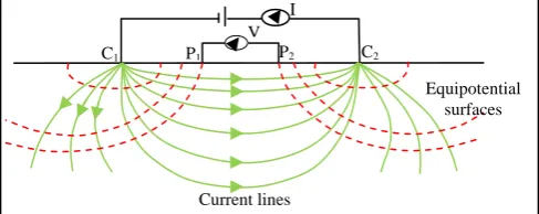
The 2D resistivity measurements are normally made by
injecting current into the ground through two current
electrodes, C1 and C2 and measuring the resulting voltage
difference at two potential electrodes, P1 and P2 (Fig. 1). The
resistivity of a soil or rock is dependent on several factors that
include amount of interconnected pore water, porosity,
amount of total dissolved solid such as salts and mineral
composition (clays). The 2D DC resistivity method is
described by [3], [4], [5] and [6].
Fig. 1. Four-point electrode configuration in a two-layer model of resistivity,
ρ1 and ρ2. I, current; U, voltage; C, current electrode; P, potential electrode
[7].
B.
Enhancing Horizontal Resolution (EHR) Technique
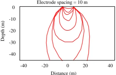
When two current electrodes are placed close to one
another, current flows along arc-shaped paths connecting the
two electrodes. About 50% of the current flows through rock
at depths shallower than the current electrode spacing
provided the earth has a constant resistivity. By increasing
Imaging Subsurface Characterization at Bukit Bunuh
Using 2D Resistivity Method: The Effectiveness of
Enhancing Horizontal Resolution (EHR) Technique
Muztaza M. Nordiana, S. Rosli, Saidin M. Mokhtar, Nordin M. M. Nawawi, and Ismail N. Azwin,
Member, IACSIT
Equipotential surfaces
Current lines
C1 P1 P2 C2
the electrode spacing, more of the injected current will flow
to greater depths, as indicated in Fig. 2a. If the electrode
spacing is much closer, current flows mostly near the earth
surface and apparent resistivity will be dominated by
resistivity structure of the near surface [8].
Fig. 2. Current flow through the earth with different electrode spacing.
III.
MATH
Using EHR technique, the current will flow close to each
other at a greater depth (Fig. 3).
Fig. 3. Current flow through the earth with EHR technique
The important part of this study is to show that EHR
technique can improve the 2D resistivity pseudo section and
prove to get deeper penetration. 2D resistivity survey is to
determine the subsurface resistivity distribution by taking
measurements on the ground surface. The true resistivity of
the subsurface can be estimated [9]. Fig. 4 shows the datum
points for Pole-dipole arrays with and without EHR
technique.
Pole-dipole array. The survey lines were directed towards
South-North and West-East direction with 5 m minimum
electrode spacing. A total of 41 electrodes were used. The
survey line of South-North direction used 2D resistivity
method without EHR technique. The survey line of
West-East direction was conducted using EHR technique
where the first electrode was located at 0 m (beginning of the
line) while the last electrode was located at 400 m (end of the
line). The inter electrode spacing of 10 m was adopted for the
study. After completion of data acquisition, the first electrode
was shifted to the right by 5 m while the last electrode was
located at 405 m and the process of data acquisition was
repeated in the same line. The two sets of data acquired for
each array was then combined during processing. The
acquired data were processed using Res2Dinv software.
a)b)
Fig. 4. 2D resistivity datum points to build up a pseudo section, a) common Pole-dipole array b) Pole-dipole array with EHR technique.
IV.
STUDY AREA
The study was carried out in Bukit Bunuh, Perak, Malaysia
(Fig. 5). The total length of the study line without EHR
technique was 6 km from South to North, parallel to Sungai
Perak. The length of study line using EHR technique 8 km,
from West to East direction, perpendicular to Sungai Perak
and two mountain ranges, Bintang and Titiwangsa Range.
Electrode spacing = 10 mDepth (
m
)
0
-10-20
-30
-40
-40 -20 0 20 40
Distance (m) Electrode spacing = 10 m
Depth (
m
)
0
-10-20
-30
-40
-40 -20 0 20 40 Distance (m)
Distance (m) Electrode spacing = 50 m
Depth (
m
)
0
-10
-20
-30
-40
V.
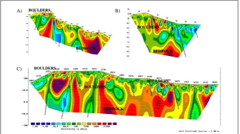
RESULTS AND DISCUSSIONSResistivity section (Fig. 6-8) show the study area consists
of two main zones. The first zone with resistivity value of
10-800 ohm-m and thickness 5-60 m was interpreted as
alluvium. There were many boulders (weathered granite)
with resistivity value of >6000 ohm-m embedded in the
alluvium. The second zone with resistivity value >20 000
ohm-m was granitic bedrock. A lot of fractures (dashed line)
were found along the survey line. The results of South-North
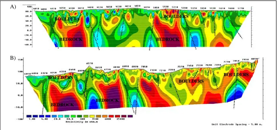
direction, without EHR technique (Fig. 6) shows the deepest
penetration is about 70 m, while East-West direction with
EHR technique is 140m (Fig. 7 and Fig. 8) with 5 m
minimum electrode spacing.
Fig. 6. Resistivity section of South-North line without EHR technique, 6 km length. A) Resistivity section 0-1000 m. B) Resistivity section 1520-4400 m. C) Resistivity section 4300-6000 m.
Fig. 7. Resistivity section of West-East line, with EHR technique. A) Resistivity section of 0-1200 m, B) Resistivity section of 1385-1995 m and C) Resistivity section of 2095-3730 m.
A)
B)
C)
A)
B)
C)
BEDROCK
BEDROCK BEDROCK BEDROCK
BEDROCK BOULDERS
BOULDERS
BOULDERS
BEDROCK
BEDROCK
BEDROCK
BOULDERS BOULDERS
BOULDERS
BOULDERS
Fig. 8. Resistivity section of West-East line, with EHR technique, A) Resistivity section of 4010-5850 m and B) Resistivity section of 6010-8020 m
VI.
CONCLUSION
The South-North and West-East direction result shows
variation in resistivity values and depth of penetration.
However, result from the EHR technique produced better
image mapping in term of resolutions and penetration depth.
This technique improves the horizontal resolution of
subsurface resistivity. Application of combining data in
resistivity surveys may be a useful strategy for improved
resistivity mapping in shallow subsurface.
ACKNOWLEDGMENTS
Authors wish to express gratitude to USM geophysics staff
together with undergraduate and postgraduate students for
assistance in geophysics data acquisition.
REFERENCES
[1] S. S. Liew, Role of Geotechnical Engineer in Civil Engineering works in Malaysia, 2010.
[2] S. J. Bullock, “Future and present trends of navigation and positioning techniques in exploration geophysics,” Geophysical Journal, vol. 92, no. 3, pp. 521, 1988.
[3] A. A. R. Zohdy, G. P. Eaton, and D. R. Mabey, Application of surface geophysics to ground water investigations: Techniques of water-resources investigations of the United States Geological Survey, 1974, pp. 116.
[4] J. S. Sumner, Principles of Induced Polarization for Geophysical
Exploration, Developments in Economic Geology 5, Elsevier Science
Publishing Co, 1976.
[5] J. M. Reynolds, An Introduction to Applied and Environmental
Geophysics, New York: Wiley, 1997.
[6] Y. Rubin and S. S. Hubbard, “Hydrogeophysics, water science and technology library,” Dordrecht, The Netherlands, Springer, vol. 50, pp. 523, 2006.
[7] A. H. Said, “Geophysical imaging of root-zone, trunk, and moisture
[9] M. H. Loke, Instruction manual for the 2D resistivity forward
modeling program Res2Dmod, 1994, pp. 1-11.
Muztaza M. Nordiana was born in Johor Bahru, Malaysia, on January 25, 1986. She was graduated BSc (2008) and MSc (2010) in Applied Science (Geophysics) at Universiti Sains Malaysia (USM), Malaysia. She is currently pursuing PhD at the same university. She is also conducting and teaching undergraduate and postgraduate students in their final year and research projects.
She has experienced working in field that involves engineering and environmental projects including slope, engineering and groundwater in all Peninsular Malaysia including Sarawak, Labuan and Brunei. Her research interest is about Geophysics in mineral exploration, engineering and environmental study.
Ms. Nordiana is a member of European Association of Geoscientists & Engineers (EAGE) and Geological Society of Malaysia. She was obtained fellowship from USM. She was a recipient of the Student Travel Grant Saint Petersburg 2012 sponsor by EAGE Student Affairs. She has published several journals and refereed proceeding papers. She was also received best paper award from International Conference of Arts, Science & Technology (ICAST 2012).
S. Rosli was born in Penang, Malaysia, on 28th February 1960. He is a senior lecturer in Geophysics section, School of Physics, Universiti Sains Malaysia (USM). He obtained his B.Sc from Universiti Sains Malaysia in 1984, M.Sc from USM in 2004 and was awarded a PhD in 2009 from USM. He has served at USM since year 1985.
Prior joining USM, he worked as Tutor in Matriculation Centre USM and School of Physics, USM. His current research activities are Engineering and Environment. He expertise is in Electrical method (2D/3D resistivity/ IP/ SP), Seismic (Refraction and Reflection), Ground Penetrating Radar, Magnetic and Gravity.
He has published several books and more than 80 journals and conference papers.
Saidin M. Mokhtar was born in Perak, Malaysia on 15th August 1963. He is currently the Director of the Centre for Global Archaeological Research (CGAR), Universiti Sains Malaysia (USM). He has involved in
A)
B)
BEDROCK BEDROCK
BEDROCK BEDROCK
BOULDERS
BOULDERS BOULDERS
He is the Malaysian first archaeogeologist. With more than 20 years experience in archaeological research throughout the country, he has led Palaeolithic studies at sites Kampung Temelong, Lawin, Tingkayu, Bukit Bunuh, Mansuli, and civilization site of Sungai Batu, and was involved in the EIA Petronas Gas and Bakun Projects. His expertise is in the field of Palaeolithic culture, palaeoenvironment, early civilization and stone tools technology and classification.
Prof. Mokhtar is an Honarary Secretariat since 2007. He is also a member of Indo Pacific Prehistory Association (1990-2012), The Bosnain Valley of the Pyramids (2000-2012) and Geological Society of Malaysia (1987-2012). He was received Universiti Sains Malaysia Excellence Award (2001), 3rd
place in booth best award in MOSTE exhibition (2000) and 1st place in booth
best award (history section) in MOE exhibition (2001). He has published several books, journals and conference papers.
Nordin M. M. Nawawi was born in Negeri Sembilan, Malaysia, on 6th July 1958. He is a professor in
Geophysics section, School of Physics, Universiti Sains Malaysia (USM). He was graduated BSc (1979) and M.Sc (1983) in Physics from Western Michigan University, USA. He obtained his Ph.D (1993) from Birmingham University, England in Geophysics.
He was a teaching assistant in Western Michigan University, USA (1981-1983). He works as a lecturer in Universiti Sains Malaysia (USM) since 1983. His research interests are Electrical Imaging and GPR for Geotechnical, Environment, Archaeology and Geophysics.
Prof. Dr. Nawawi is a member of European Association of Geoscientists and Engineers (EAGE), Environmental and Engineering Geophysical
Society (EEGS), Institute of Geology Malaysia and Geological Society of Malaysia. He was received Universiti Sains Malaysia Excellence Award (1998), Japanese Society for the Promotion of Science (JSPS) General Exchange Program Fellowship – Kyushu University (2000), Australian Endeavour Executive Award (Second Round) – Monash University, Australia (2010) and Ludger Mintrop Award 2012 presented to La Hamimu, Jamhir Safani and Mohd Nawawi for best paper published in Near Surface Geophysics for the year 2011. He has published several books, journals and conference papers.
Ismail N. Azwin was born in Kedah, Malaysia, on 25th September 1987. She is currently a post-graduate student in Universiti Sains Malaysia (USM) pursuing her PhD in seismic and electromagnetic wave propagation characteristics. She graduated from USM in Master of Science (Geophysics) in September 2011 regarding the application of geophysical methods in engineering and environmental problems. She obtained her BSc from same university in August 2009.
She has field work experiences concerning geophysics-related in engineering and environmental projects including slope stability, groundwater exploration, constructions and also in archaeological research. Her research interest is about Geophysics in engineering and environmental study.