Abstract:––In this paper, a new architecture for DSSS signal acquisition has been proposed and implemented. With the increased requirement of data security and authentication, it is essential to use large PN sequence like Galois GF (2) in the spreading and dispreading operations of DSSS communication. Spreading with a large PN sequence ensures the increased frequency spectrum utilization with ultra narrow band (UNB) channels. An effective and efficient digital modulation technique like QPSK is used for improved accuracy. It also provides acquisition even at low SNR. The simulation results performed on both MATLAB and CPLD (XC3s100evq100-5) shows that the signal acquisition is comparatively improved in terms of low SNR, low power and low complexity.
Key words:––DSSS, Galois sequence, Low SNR, MATLAB, CPLD, VHDL, VLSI
I.
INTRODUCTION
Among the various spread spectrum techniques, PN DSSS QPSK technology has various advantages like low power density spectrum, low probability of intercept (LPI), powerful anti jamming performance, multiple access capability, high bandwidth efficiency and convenient demodulation [1]. Hence it is widely used in military communication, weapon guidance system and modern commercial communications. Generation of a spreading code along with a modulation technique such as phase shift keying (PSK), prior to transmission is vital in DSSS communication. The DSSS receiver must synchronize with this spreading code prior to demodulation [2]. After researching on the limitations of the traditional DSSS architectures, a new approach of generating the spreading code, namely Galois sequence, is proposed and implemented. QPSK modulation method has been used to ensure high quality signal acquisition as it has the advantage of converting a narrow band signal into broadband thereby improving the quality of reception, especially in case of decreased signal strength. Various spreading techniques have been investigated and low SNR signal acquisition has been demonstrated in this paper. The component details of both transmitter and receiver along with the sub blocks have been discussed.
This paper is organised as follows: In section II, the basic principle of DSSS communication is discussed. The various advantages of DSSS communication over its counter parts are given in detail. In section III, the existing DSSS architectures are discussed. The limitations and alternative measures to counter the drawbacks of these architectures are discussed. Section IV introduces the proposed architecture and various sub blocks present in it are introduced in detail. In section V provides the performance measures of the proposed architecture.
II.
DSSS
COMMUNICATION
Spread spectrum is a method in which a signal generated with a specific bandwidth is spread in frequency domain that results in a new signal with a wider bandwidth. Hence the bandwidth of the transmitted signal is much larger than that of the frequency content of message signal. Spread spectrum communication may employ direct sequence spread spectrum (DSSS), frequency hopping spread spectrum (FHSS) or hybrid of these two. These techniques have low probability of intercept (LPI) i.e. decreasing the interference from the neighbouring receivers thereby providing privacy.
FHSS is generally used to provide channel clearing time in multipath environment. It is a single user FSK system. The transmitter in such system utilizes a set of predefined frequency bins which are generally selected to exceed the maximum multipath delay. It ensures that no frequency bin is reused before the channel is completely cleared. This selection of large bin reduces coincidence, error rate and the required coding gain. The interference between the users is not only because of the coincidences of using same band at same time but also due to the multipath. Hence the performance is measured by the multipath profile and the amount of power outside the symbol period. Hence maximizing the number of users requires large number of frequency bins which results in a bandwidth relatively narrow. This corresponds to setting the tone duration to be long with respect to channel clearing time. The resultant narrow bands are subjected to fading effect and smaller Doppler shift [3].
Fig. 1: Principle Block Diagram of DSSS Communication.
DSSS technique involves speeding and de-spreading of the message signal in frequency domain. It utilizes a PN sequence for this purpose as shown in Fig. 1. An m-user DSSS system involves m n-length codes for spreading. These codes are used to modulate a binary data stream [0, 1] mapped to [-1, 1]. A single user receiver is used to multiply the signal by the original code. This process is called de-spreading. The SNR at the output stage after de-spreading is n times greater than the SNR at the input stage. Hence acquisition of low SNR signals can be greatly achieved by using this technique. The concept of DSSS provides high data security and reduced interference as spreading and de-spreading is done by codes generated from a PN sequence rather than frequency bins. De-spreading has the additional advantage of de-correlating multiple access interference (MAI). This is possible because the interfering signals have spreading codes orthogonal to the desired users spreading codes.
III.
EXISTING
DSSS
ARCHITECTURES
Various architectures are available for implementing DSSS transmitter and receiver. They are:
A FET based architecture: It employs a class D power FET for generating the spread signal from the message signal. It suffers from the problem of electromagnetic interference. The architecture has less immunity towards noise and hence it fails to transmit signals appreciably as the distance between the transmitter and receiver increases.
FFT based architecture: The data security in this type of architectures is limited as the pattern can be predicted. PN sequence based architectures: In this type of architectures, a random sequence is generated for spreading the
code. These architectures are effective, in terms of data security, only when the sequence is large enough.
The problem of electromagnetic interference (EMI) present in the conventional architectures can be avoided by using a large PN sequence, like Galois sequence, which generates random data bits. The limited data security problem, which is a major drawback in the existing architectures, can be avoided with the use of Galois sequence. The signal acquisition at low SNR is a major challenge in most of the communication systems such as satellites. This problem can be avoided with the use of QPSK which converts narrow band signal into baseband.
As the technology is improving day by day, there is a need for high data security. Ordinary PN sequence with 3 to 4 bits in a code sequence can be easily predicted. Hence to ensure security, large PN sequences are required. As the proposed Galois structure provides large number of code streams, the data security is high. As the SNR of the original signal is increased by 16 times, acquisition of low SNR signal is possible using this structure. The XOR gates shown can be replaced by XNOR gates. The position of these gates can also be changed to generate various new code sequences [4].
IV.
PROPOSED
ARCHITECTURE
The codes must be of low cross correlation value
The codes should be balanced i.e. the difference between ones and zeros may be as low as is sufficient for good power spectral density.
A PN sequence is generally implemented by using linear feedback shift registers which consists of a few shift registers and XOR gates. A pair of two linear feedback shift registers generates a Gold code. A Gold code sequence is preferred as it provides minimum cross correlation. Walsh Hadamard sequence and Kasami code sequence also have the same advantage [5].
All the sequences mentioned above have the following limitations:
There is no offset between the streams. Hence every sequence does not start with a new start point The propagation times are more
The software implementation is complex, especially in case of Gold code and Kasami code.
To overcome these limitations, an alternative structure which can generate the output stream as that of a conventional LFSR but with offset in time has been implemented. This structure is called Galois configuration.
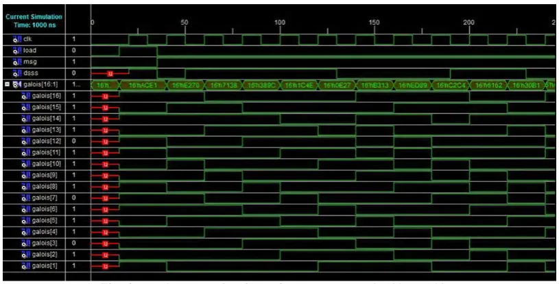
In this configuration, when the system is clocked, the bits that do not have taps are shifted right as it is but the bits with taps are XORed with the output bit and then shifted right. A sixteen bit Galois LFSR is shown in Fig. 3
Fig. 3: Block Diagram of Galois Sequence
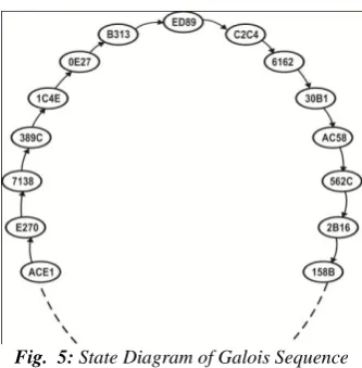
This structure can provide a cycle of 65535 states excluding all zeroes state. The state shown in Fig. 4. is equal to ACE1 hex which is followed by E270 hex.
Fig. 4: Galois Sequence Working Diagram
Fig. 5: State Diagram of Galois Sequence
4. 2 .QPSK TECHNIQUE
An I / Q modulation technique is required to modulate and demodulate these encoded data bits. Quadrature phase shift keying (QPSK) modulation is chosen as the target I / Q modulation technique. The purpose of QPSK modulation in the proposed system is to convert the data bits into physical layer symbols and vice versa. These symbols are used as the transmission bits between the physical layers present at transmitter and receiver, in an OSI reference model. This capability is an essential factor in case of anti jamming application of DSSS communication [6].
4. 3 .WORKING OF THE ARCHITECTURE
The proposed architecture is indeed an extension of the existing PN sequence based architecture. It uses a Galois sequence rather than an ordinary PN sequence. Use of this new sequence provides 65,535 unique combinations of spread stream ensure secured transmission of data. The major blocks present in the new architecture are Galois sequence generator and QPSK modulator & demodulator.
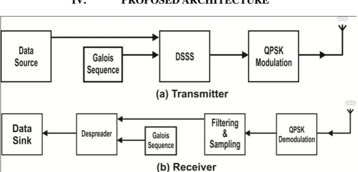
The transmitter of proposed DSSS architecture contains the data source,Galois sequence generator, DSSS block and QPSK modulator. The Galois sequence generator generates various unique sequences which are feed to the DSSS block along with the message signal. A logical operation such as XOR (or) XNOR needs to be performed on these two signals within the DSSS block. The pattern of Galois sequence changes instantly with its output bit. This random sequence called the spreading stream is XORed with the message signal to produce an encoded signal called DSSS signal. QPSK modulation is performed on this encoded data for transmission. Reverse operation is performed at the receiver stage. The demodulated signal i.e. DSSS signal along with the Galois sequence which is the spreading code is applied to the de-spreader. An XOR (or) XNOR block can act as a de-spreader. After dispreading, we obtain the original data stream that was transmitted.
V.
PERFORMANCE
ANALYSIS
The proposed architecture is implemented using CPLD (XC3S100EVQ100-5).The simulator used in Xilinx 9.2i with Xilinx XST synthesis II. The RTL schematic thus generated is shown in Fig.6
Fig. 6: RTL Schematic of the Proposed Architecture
Fig. 7: VHDL Test Bench Setup for Simulation.
The simulation results obtained for this test bench on CPLD (XC3S100EVQ100-5) shows that the proposed architecture provides high accuracy and security compare to the conventional methods as can be seen from Fig-8
Fig. 8: Simulation Results Obtained Using CPLD (XC3S100EVQ100-5)
The architecture is targeted for low SNR signal acquisition of DSSS signals. QPSK modulation technique is used for this purpose. The statistical analysis of SNR is considered with a signal in noise. In this case, we represent the noisy output as
y t = n1 t + jnq t (1)
To counter the noise, we consider the long base band DSSS signal r (t) intercepted by the receiver as y (t). Then we divide y (t) into m segments. Hence, the auto correlation of m-th segment is given by
Ry m τ
= 1
T y t y t −τ dt T
0 (2)
The integration on equation (2) now provides
y t y∗ t −τ = n
q t n1 t − τ − nq t nq t + j n1 t − τ nq t − nq t nq t (3)
From equation (2) and central limit theorem, the real and imaginary parts of Ry (τ) approximately obeys Gaussian distribution, with mean and variance as follows:
E Re Ry τ = E Im Ry τ = 0 (4) Var Re Ry τ = Var Im Ry τ = σn
4
2T (5)
Hence the mean and variance of the noisy signal ρ2 (τ) is given by
mρ2= E ρ2 τ = E p τ
E p τ = 1 (6)
σρ22= Var ρ2 τ = Var p τ
E2 p τ =
1
M (7)
modulation is a method which converts the given DSSS signal in to M symbols. Using this method, the acquisition of low SNR signals is possible.
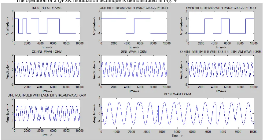
The operation of a QPSK modulation technique is demonstrated in Fig. 9
Fig. 9: Simulation Result of QPSK Using MATLAB
An input base band signal is modulated using QPSK. The simulation of QPSK modulation technique has been performed in MATLAB. The odd and even bit streams of the input bit stream are considered separately. The odd bit streams are multiplied by a cosine waveform where as the even bit stream is multiplied by a sine waveform. The summation of these two waveforms provides the required QPSK signal.
The device utilization summary of the proposed architecture is shown in Fig. 10. It is evident from this summary that the architecture is less complex as it uses less number of components and is of low power circuit. The device utilization is very less which provides an ease of designing more number of such circuits on a single IC.
Fig. 10: Device utilization summary of the proposed architecture
VI.
CONCLUSION
AND
FUTURE
WORK
From the above simulation results and synthesis thereafter, the following results are observed:
The performance of DSSS system was improved as the design was less complex and has less propagation delay. The use of QPSK modulation technique has provided the required number of symbols to retrieve signal even at
low SNR condition.
The architecture has the advantage of VLSI implementation which, intern, produces compact DSSS architecture and devices for future needs of 4G communication.
The DSSS system has been implemented using lucid structures which are of low cost.
In future, the concept used in the proposed architecture can be prolonged to other m –ary phase shift keying methods for better performance.
2. ACKNOWLEDGEMENT
Code Sequence, 2008 11th IEEE international conference on communication technology proceedings 5. Muhammad Baqer Mollah, Md. Rashidul Islam, Comparative Analysis of Gold Codes with PN Codes
6. Using Correlation Property in CDMA Technology, 2012 International Conference on Computer Communication and Informatics (ICCCI -2012), Jan. 10 – 12, 2012, Coimbatore, INDIA