Experimental and Numerical Prediction of Spring
back in U-bending Process
N. Fouda
*, R. El-Bana
**, and M. Samuel
**** Assoc. Prof. in Production & Mechanical Design Dept., Faculty of Engineering, Mansoura University, Egypt.
**Demonstrator of Prod. Eng., Mansoura College Academy, Egypt.
*** Prof. in Production & Mechanical Design Dept., Faculty of Engineering, Mansoura University, Egypt.
Abstract-- One of the most sensitive features of sheet metal forming processes is the elastic recovery during unloading, called spring back, which leads to some geometric changes in the product. In this paper spring back dependence on the mechanical properties of different materials and tools geometry has been examined numerically and experimentally in sheet metal U- bending test. The computer code MARC was used to simulate the U- bending process under plane strain condition. A Comparison between the experimental and the finite element simulation results also performed. A complete knowledge of the spring back phenomenon and its dependence on material and process variables is strongly required in order to develop effective real time process control systems.
Index Term-- U-bending, spring back, FEM, numerical simulation.
1. INTRRODUCTION
As a fundamental and traditional process in metallic forming technologies, sheet metal forming is widely being employed in almost all industrial fields. Needless to say, it is because a final sheet product of desired shape and appearance can be quickly and easily produced with relatively simple tool set. However, sheet metal forming may frequently produce the unacceptable products with wrinkle, tear, poor dimension precision, and so on, unless tool and process parameters are appropriately chosen. After the sheet metal forming process, residual stress remains at the final product due to the plastic deformation. The residual stress leads to elastic recovery of the formed part which called spring back that causes shape error in final product [1]. Spring back can be defined as an elastically-driven change of shape of a deformed product which takes place during removal of external loads. It is a complex physical phenomenon which is mainly governed by the stress state obtained at the end of a deformation [2]. Hence, the tool design, for given specific sheet material and final product dimension, should be based upon the accurate prediction of amount elastic recovery. Nevertheless, the determination of process parameters had been traditionally made according to a trial and error procedure, by invoking the designer’s empirical are know-how or expensive and time-consuming experiments [3, 4]. The main reasons are as follows: First, the elastic recovery phenomenon is influenced by a combination of various process parameters, such as the tool shape and dimensions, the temperature change and frictional contact condition, the material properties, and so on.
Second, the prediction accuracy by analytical approach is quite low because of the limitation in mathematical modeling of process and solving methods. Of course, such a limitation is resulted from the problem nonlinearity and other process complexities [5].
Fortunately, the advances in numerical simulation techniques, such as the finite element method and the numerical optimization, have been relaxing such a limitation, so that the accurate elastic recovery prediction and the systematic tool design are in a rapid development growth [6, 7]. During the past two decades, number of researchers have investigated and attempted to obtain a basic understanding of spring back behavior [8-17]. In this paper, we intend to investigate the parametric dependence of spring back amount on the major process parameters through the spring back simulation of a plane-strain sheet metal U-bending. For this goal, experimental and numerical studies of the effects of tool geometry and material properties of U-die bending processes have been conducted. Results of the experiments were also compared with those of the finite element simulations.
2. NUMERICAL
Analysis of bending process based on consideration of the plane strain condition is conducted using FE mesh for the axisymmetric continued flat samples. The finite-element computer code (Marc Mentat 2010.1.0 FEM software) was used to simulate strain distribution across the sheet thickness and spring back parameters calculation. Plane-strain quadrilateral four-noded isoperimetric elements with bilinear interpolation were used for this simulation. Fig.1 shows a two-dimensional symmetric finite element model for the numerical simulation, the profile of the die, punch, the initial shape and FE mesh are applied. Four rigid surfaces were used to simulate the punch, die, blank holder, and ejector. The detailed dimensions of tools and material properties are listed in Tables 1 and 2. A finer mesh is generated between the punch and die for increasing the simulation results accuracy.
3.EXPERIMENTAL
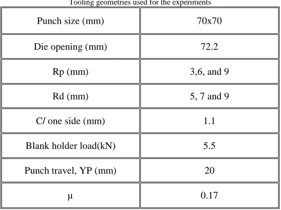
mm gauge thickness with die profile radius Rd = 5mm, 7mm and 9mm. Moreover, different values for each of the punch profile radius, Rp, and coefficient of friction between tools and strip with 1.1 ho clearance were used for these experiments. Table 1, shows the mechanical properties of tested materials, and Table 2 shows the tool geometries and forming conditions used in the experiments. The samples were prepared by cutting sheets into strips (rolling direction lengthwise). The final dimensions of the strips were 200 mmˣ60 mm. Punch travel was stopped automatically after 20 mm to produce samples of the same wall height.
A universal testing machine with a capacity of 300 kN was used for experiments. The tests were performed at a constant velocity. After placing the blank on the die (under the blank holder), the punch holder which was attached to the ram of the machine is moved against the die holder. The bending
process was divided into two stages; in the first stage, called loading, the punch moved down until its stroke reached a specific value, 20 mm. In the second stage, named unloading (spring-back), the punch moved up. In U-die bending, the effect of punch profile radius on spring-back was studied for the sheet thickness 1 mm at different values of die profile radius. Also, the effect of materials properties was examined for die profile radius 5, 7 and 9 mm at various punch profile radius; thus 27 tests were totally performed for this die set.
4. SPRING BACK MEASURMENT
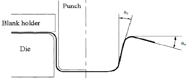
The amount of spring back of each blank was measured using spring back parameters of spring back angles θx and θy as shown in Fig.3. The method with which these angles were measured also illustrated in Fig.4.
Fig. 1. The initial shape and FE mesh
Nomenclature
FEM finite element method BHF blank holder force Rp punch profile radius
Rd die profile radius
h○ original thickness of strip
Cclearance between punch and die E modulus of elasticity
n strain hardening exponent r normal anisotropic parameter µ Coulomb friction coefficient υ Poisson's ratio
Є○ initial strain
σy yield stress
θx spring back parameter developed in the flange
Fig. 2. Schematic and photograph for experimental set-up.
Fig. 3. Illustration of the u-bending process and the spring back angles after unloading.
Fig. 4. Schematic illustration of the way used to measure the specimens’ spring back angles
Table I
Material properties from experimental tests and used in the simulations model.
Material Aluminum alloy
(SAE 5754)
Mild steel (SAE1008)
Stainless steel (AISI 304)
h○(mm) 1 1 1
E (GPa) 71 206 206
σy(MPa) 136 178.1 278.2
r 0.65 1.78 1.66
υ 0.34 0.3 0.3
Є○ 0.017 0.0072 0.0128
n 0.359 0.259 0.218
Table II
Tooling geometries used for the experiments
Punch size (mm) 70x70
Die opening (mm) 72.2
Rp (mm) 3,6, and 9
Rd (mm) 5, 7 and 9
C/ one side (mm) 1.1
Blank holder load(kN) 5.5
Punch travel, YP (mm) 20
µ 0.17
5. RESULTS AND DISCUSSION
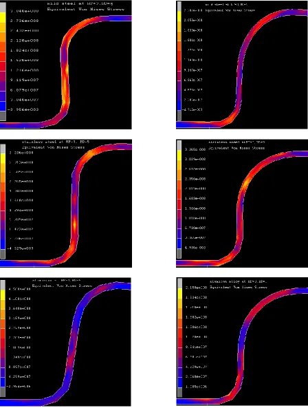
5.1. Effect of process variables on the equivalent Von Mises stress and total plastic strain
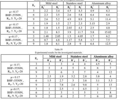
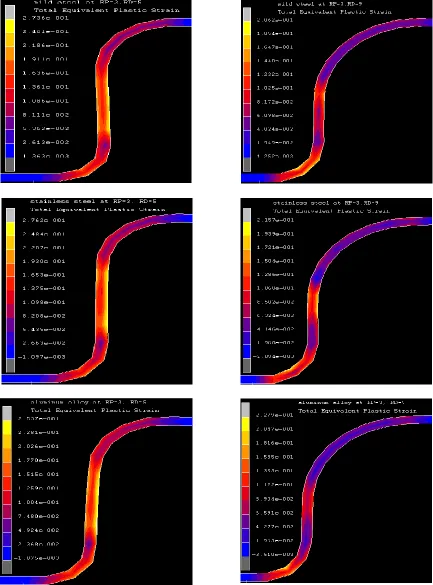
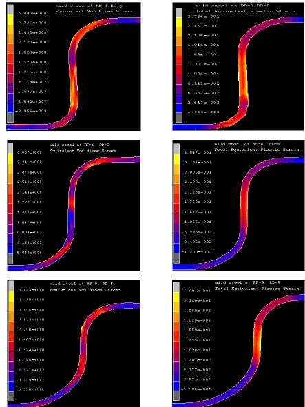
Figs.5-7 show the effect of the die profile radius and punch profile radius on the equivalent Von Mises stress and total plastic strain for the tested materials. In Figs.5 and 6, the equivalent stress and total plastic strain decreased as the die profile radius increased with punch profile radius =3mm.InFig.7 the equivalent stress and total plastic strain for mild steel increased as the punch profile radius increased with die profile radius =5mm due to the increasing of sheet stretching at punch profile radius.
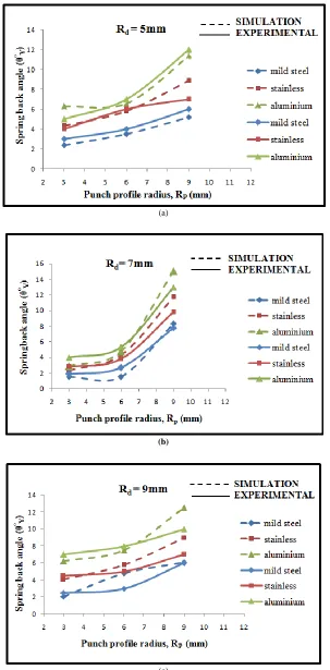
5.2. Effect of die profile radius on the spring back angle Fig.8 shows the effect of die profile radius on the spring back angle θX at three different values of RP. It was noted
that θX inversely preoperational with Rd for the three
materials used. Since the amount of the spring back developed in the flange of the deformed part decreased as the Rd increased because of the decreasing of the bent ratio. 5.3. Effect of punch profile radius on the spring back angle
Fig.9 shows the effect of punch profile radius on the spring back angle θY at two different values of Rd. It was
noted that θY directly preoperational with RP for the three
materials used. Since the spring back value developed in the wall of the U- bent part increased as the RP increased. 5.4. Effect of the material properties upon the spring back angle
Fig.10 shows the experimental and numerical effect of material properties on the spring back parameters of the three different materials used. It can be seen that the spring back for stainless steel are higher than those for mild steel. It is noted also that the aluminum alloy shows the highest values of spring back than the stainless and mild steels. This
is due to the fact that the yield stress-to-modulus of elasticity ratios for mild steel is greater than stainless steel, and for stainless steel greater than aluminum alloy. Note also that the greater the magnitude of this ratio, the greater the effect on the spring back. In addition, the spring back parameters increase as the strain hardening exponent (n) increase or as the normal anisotropic value(r) decrease. A summary of the above results are tabulated in Tables III and IV for both numerical and experimental models.
6. CONCLUSION
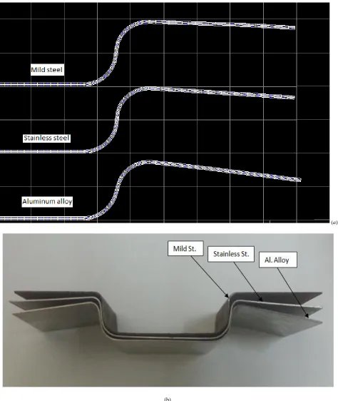
An attempt, based on the experiment and the simulation, was made to explore the effects of material variables and tool geometry on spring back phenomenon in U- bending process. A numerical model based on the updated Lagrangian formulation has been proposed in this paper to calculate spring back in a plane-strain draw sheet forming problem. The model took into consideration the material properties tool geometry. The model implemented using the MARC FE package. For comparison purposes, various results regarding the unloaded shape of the spring back predictions were calculated using the FE computer program .These results were then compared with experimental measurements. The comparison indicated that the numerical model is capable of predicting spring back in 2D draw bending very accurately. Based on this study, the following remarks are drawn.
1. Spring back in the wall of U-drawn section increased with the punch profile radius.
2. Spring back in the flange of U-drawn part decreased as the die profile radius increased. 3. Spring back parameters increased as the strain
hardening exponent increased.
5. Results from the experimental set-up agree very well with those from the theoretical model.
REFRENCES
[1] Min Kuk Choi, Hoon Huh. Effect of punch speed on amount of spring back in U-bending process of auto-body steel sheets. ICTP 2014, 19-24 October 2014.
[2] Bushra Rasheed Mohameed, Ethar Mohamed Mhdi Mubarak, Nawal H. Alsalihi. Effect of Die’s Shape, Sheet Thickness and Type of Alloy on the Spring back Phenomenon. Eng. & Tech. Journal, Vol.30, No.9, 2012.
[3] Y.M. Huang, D.K. Leu. An elasto-plastic finite element analysis of sheet metal U-bending process. J. Mater. Process. Technol. 48 (1995) 151–157.
[4] Z. Hu, L. Zhu, B. Wang, Z. Liu, Y. Miao, P. Xie, S. Gu, W. Sheng. Computer simulation of the extrusion of a thin-walled cup using the thermo-mechanically coupled elasto-plastic FEM. J. Mater. Process. Technol. 102 128–137, 2000.
[5] J.R. Cho, S.J. Moon, Y.H. Moon, S.S. Kang. Finite element investigation on spring-back characteristics in sheet metal U-bending process. Journal of Materials Processing Technology 141 (2003) 109– 116.
[6] N.M. Wang, B. Budiansky. Analysis of sheet metal stamping by a finite element method. ASME J. Appl. Mech. 100 (1978) 73–82. [7] S. Kobayashi, S.I. Oh, T. Altan, Metal Forming and the Finite
Element Method. Oxford University Press, Oxford, 1989.
[8] M. Samuel. Experimental and numerical prediction of spring back and side wall curl in U-bendingsof anisotropic sheet metals. Journal of Materials Processing Technology 105 (2000) 382_393.
[9] M. Bakhshi-Jooybari *, B. Rahmani, V. Daeezadeh, A. Gorji. The study of spring-back of CK67 steel sheet in V-die and U-die bending processes. Materials and Design 30 (2009) 2410–2419.
[10] Tekiner Z. An experimental study of the examination of spring-back of sheet metals with several thicknesses and properties in bending dies. J Mater Process Technol 2004;145:109–17.
[11] Moon YH, Kang SS, Cho JR, Kim TG. Effect of tool temperature on the reduction of the spring-back of aluminum sheets. J Mater Process Technol 2003;132:365–8.
[12] Li X, Yang Y, Wang Y, Bao J, Li S. Effect of the material-hardening mode on the spring-back simulation accuracy of V-free bending. J Mater Process Technol 2002; 123:209–11.
[13] Cho JR, Moon SJ, Moon YH, Kang SS. Finite element investigation on spring back characteristics in sheet metal U-die bending process. J Mater Process Technol 2003; 141:109–16.
[14] Xu WL, Ma CH, Li CH, Feng WJ. Sensitive factors in spring-back simulation for sheet metal forming. J Mater Process Technol 2004;151:217–22.
[15] Gomes C, Onipede O, Lovell M. Investigation of spring-back in high strength anisotropic steels. J Mater Process Technol 2005; 159:91–8. [16] Papeleux L, Ponthot JP. Finite element simulation of spring-back in
sheet metal forming. J Mater Process Technol 2002; 125–126:785– 91.
[17] Thipprakmas S, Rojananan S. Investigation of spring-go phenomenon using finite element method. J Mater Des 2008; 29:152 6–32.
Table III
Results from simulation for the investigated materials
Table IV
Experimental results for the investigated materials.
Rp
Mild steel Stainless steel Aluminum alloy
θxᵒ θyᵒ θxᵒ θyᵒ θxᵒ θyᵒ µ= 0.17
BHF=5550N , Rd= 5. Yp=20
3 2.2 3.4 4.5 4.3 4.9 6.3
6 2.3 3.5 2.6 5.8 6.4 6.6
9 2.6 5.2 4.9 8.9 5.1 11.4
µ= 0.17 BHF=5550N ,
Rd= 7. Yp=20
3 1.9 1.5 2.7 2.3 3.15 2.9
6 1.8 1.5 2.03 4.3 2.5 4.8
9 2.1 8.3 3.9 11.7 5.8 15.02
µ=0.17 , BHF=5550N ,
Rd= 9, Yp=20
3 1.48 2.05 1.5 4.05 1.7 6.2
6 0.7 4.8 1.17 5.8 1.7 7.5
9 1.8 6.1 2.8 9 6.4 12.5
Rp
Mild steel Stainless steel Aluminum alloy θ ᵒ
x θ ᵒy θ ᵒx θ ᵒy θ ᵒx θ ᵒy
µ= 0.17, BHF=5550N,
Rd= 5, Yp=20
3 3 3 4 4 4.5 5
6 3 4 5 6 6 7
9 2 6 3 7 4 12
µ= 0.17 BHF=5550N ,
Rd= 7, Yp=20
3 2.5 1.9 3.2 2.8 3.8 4
6 1.5 2.7 3 3.8 3.1 5.3
9 2 7.8 2.6 9.8 5 13
µ=0.17, BHF=5550N,
Rd= 9, Yp=20
3 1 2.5 1 4.5 2 7
6 1 3 1 5 1 8
Fig. 5. Influence of die profile radius on the equivalent Von Mises stress, (on left) Rd=5mm, (on right) Rd=9mm, for mild steel, stainless steel and aluminum alloy
Fig. 6. Influence of die profile radius on the total plastic strain, (on left) Rd=5mm, (on right) Rd=9mm, for mild steel, stainless steel and aluminum alloy
(a)
(b)
(c)
(a)
(b)
(c)
(a)
(b)