Abstract— In recent years, “Digital Mine” has been an important research direction in the field of geology and mineral resources. In particular, three-dimensional network modeling of mine tunnel with its spatial analysis is an important research perspective. It is significant research direction on theoretical study of “digital mine”, mineral resources exploration, mining decision-making management, mine production and mine safety etc. In order to seamlessly integrate the models of simple tunnel and intersected complicate tunnel, directed double nodes approach and midpoint interpolation approach were proposed; In order to solve the problem that the two corresponding half-tunnels will crack at sharp turning, the uniform height approach on section arch was proposed. Using Windows XP as the platform, MS Visual C++6.0 as development tools and OpenGL graphics package as the graphic processing display tools, the experimental system of three-dimensional tunnel network model was designed and developed. Using real mining data, the experimental system was tested. It is shown that the proposed method is the practical and effective.
Index Terms—Digital Mine, Tunnel, Modeling, Three Dimensions.
I. INTRODUCTION
In the digital era, the traditional mining engineering experiences the tremendous development. Tunnels are the channels through which the mineral products are transported from workface to ground. They also can be used to ventilate fresh air and deliver workers. For the whole mine, tunnels are key parts to mine projects. Thus they are a significant part of 3D tunnel modeling on DM field. Many researchers have paid a lot of efforts in modeling 3D tunnels. Yang et al. (2004) utilize cylinder to represent 3D tunnel and the auxiliary function to build 3D tunnels [1]. However the disadvantage is that this method cannot handle the situation when the tunnels intersect, and cannot guarantee the inner connectivity of 3D tunnels. Therefore, the approach is rigid and inflexible. Chen et al. (2004) directly used quasi tri-prism volume (QTPV) to simulate the underground tunnel [2]. They choose QTPV since it is a potential 3D spatial data model. QTPV can not only establish internal geological structure, but also create topological relations among the geological entities. It is
Manuscript received July 10, 2011, revised August 15, 2011. This work was supported by National Natural Science Foundation of China ( : 40972204) and Education Department of Shaanxi Province (2010JK682).
Zhang Zhi-hua is with the School of Mathematics, Physics and Software Engineering, Lanzhou Jiaotong University, Lanzhou, China (e-mail: [email protected]).
Hou En-ke, is with Xi’an University of Science and Technology, Xi’an, China. He is now with the School of Geology and Environment, (e-mail: houek@163. com).
Luo Xiao-xia is with the College of Computer Science and Technology, Xi’an University of Science and Technology, Xi’an, China (e-mail: [email protected]).
suitable for modeling geological exploration engineering. Although it is a potential three-dimensional data model, it cannot guarantee connectivity within the tunnels and the intersection among tunnels. Wei et al. (2005) expressed 3D tunnel model by using 3D facial model (framework) [3]. They divided the arch of tunnel into 8 segments (the arch is half circle, the step length is P/8.0). After the section data obtained, the whole tunnel was described. TIN (Triangulated Irregular Network) were utilized to deal with intersection of tunnels, it will increase the data storage and the difficulties of 3D modeling. It is difficult to be applied in the modeling of complex tunnel network. Zhang H.M et al. (2007) utilize the Bezier curves to simulate 3D tunnel [4]. They decompose the 3D tunnel into roof, bottom, and two profiles. The bottom and two profiles were approximated by using polygons, which can easily be generated by OpenGL. The arch roof was fitted by Bezier curves. Sun et al. (2007) proposed the approach that the tunnel was simulated by constraint triangulations [5]. They also addressed the issue of intersection. However, for complex tunnel network, it would increase the difficulty of modeling. Based on framework model, Wang (2005) deeply studied arch section, and subdivided the arch into 15 parts [6]. Based on these parts, they developed the intuitionistic model. It cannot be applied to model different types of tunnel sections. Moreover, many researchers have studied the modeling of tunnel, but they didn’t take tunnel’s intersection into consideration [7-12].
Although beneficial explorations for 3D tunnel modeling were researched by many scholars, there are many problems existed in 3D tunnel modeling, such as intersection modeling of tunnel, spatial analysis and query of 3D tunnel, etc. 3D mining softwares of overseas were lack of the processing and shown about intersection modeling of 3D tunnel, such as Surpac. According to these shortcomings, we have proposed some modeling methods to solve the problem of muti-intersection of tunnels; meanwhile, the complex tunnel would be constructed easily.
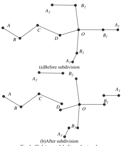
The basic idea of subdivision: skeleton model of Tunnel network, which is expressed by nodes and centerlines (such as Fig.1 shows), can be used to subdivide complex tunnel network into simple-tunnels and complex-tunnels. Those subdivided tunnels were built respectively, three-dimensional tunnel network model were integrated by those simple-tunnels and complex-tunnels. Namely, the skeleton of intersection is collection, named PART-TWO, which is set of complex-tunnels, the rests can be looked as other collection, namely PART-ONE, which is composed of
Integration Method of Three-dimensional Complex Tunnel
Network Model
Zhi-hua Zhang, En-ke Hou, and Xiao-xia Luo
the single-tunnels. Then, the whole tunnel network can be combined of PART-ONE and PART-TWO [13-15].
A
B
C
D O B1
A1
B2
A2
B3
A3 (a)Before subdivision
A
B
C
D O
B1
A1
B2
A2
B3
A3 (b)After subdivision
Fig. 1. Skeleton model of tunnel network
The concrete division process: As for intersected part, the intersected node is look as center, which can extend to each branch tunnel. The nodes, which are adjacent to intersected node, are classified as node set of PART-TWO. The centerline set consists of the lines which are composed of the intersected node and its adjacent node. As to single-tunnel, its node set is made up of all the nodes on the single-tunnel, including the node which is adjacent to intersected node. As shown in Fig.1, we will take Fig.1 (a) for example, it is a cross intersection, A, B, C, D, A1, B1, A2, B2, A3, B3, O are nodes, O is intersection node (center node), according to the principle of division, there are D, B1, B2, B3 neighboring with O, so the node set of PART-TWO is {D, B1, B2, B3, O}, link set is {DO, B1O, B2O, B3O}. The node set of PART-ONE is {{A, B, C, D}, {A1, B1}, {A2, B2}, {A3, B3}}, and its link set is {{AB, BC, CD}, {A1B1}, {A2B2}, {A3B3}}. As shown in Fig.1 (b), there are four mutual independent single tunnels which construct the PART-ONE. The divided principle of trifurcate tunnel and multi-intersections tunnel is the same as cross-section tunnel. If there are n points adjacent with intersection node, the node set of PART-TWO has n+1 nodes, and its link set has n centerlines.
The advantage of this subdivision: (1) the tunnel network is simplified, so that the structure of tunnel network is clarity. (2) As for modeling of PART-ONE, we adopt wireframe to build. (3) In the order of PART-ONE modeling, as long as several single tunnels are separate complete. During the modeling, it needs not to consider the modeling order. For example, there are three single tunnels: a, b, c. a can be modeled first, b or c can be modeled first too. For a single-tunnel, if the modeling sequence of nodes is A→B→
C, then the sequence C→B→A is also possible. (4) There are many intersection parts in PART-TWO, every part is individual on the aspect of modeling, regardless of the orders.
According to Fig.1 (b), the tunnel network is subdivided
into PART-ONE and PART-TWO, the basic information of two parts are shown in Table I and Table II.
TABLE I: BASIC ELEMENTS OF PART-ONE
Tunnel line Arcs nodes
ABCD AB, BC, CD A, B, C, D
A2B2 A2B2 A2, B2
A1B1 A1B1 A1, B1
A3B3 A3B3 A3, B3
TABLE II: BASIC ELEMENTS OF PART-TWO
Tunnel line Arcs nodes DOB2 DO, OB2 D, O, B2
B2OB1 B2O, OB1 B2O, OB1
B1OB3 B1O, OB3 B1O, OB3
B3OD B3O, OD B3O, OD
III. THE NTEGRATION I O F MODELS
As mine tunnel network is crisscross and more complex, it is difficult to build the whole three-dimensional network model. So, we need to subdivide the complex tunnel network in order to construct three-dimensional tunnel model easily. No matter what the tunnel network is more complex, it can be split in terms of intersected node. There are three tunnel branches in intersected node at least (n≥3, n represents single tunnel branches).
A
B
C
D
E
Fig. 2. Skeleton model of single-tunnel (PART-ONE)
As Fig.2 shown, there is skeleton information of single-tunnels in PART-ONE, PART-TWO contains the skeleton information of complex-tunnels, includes intersection among tunnels (Fig.3). Commonly, there are three types in intersection tunnels: intersection of three tunnels (Fig.3a), intersection of four tunnels (Fig.3b), intersection of n-tunnels (n>=5, Fig.3c). No matter what the types are, there is integration between PART-ONE and PART-TWO, then it is the necessary problem to be solved that is realized seamless integration between PART-ONE and PART-TWO. We will discuss the different situations in the following part.
A
B D
C
B
C E D
A
A
B
C
D E
F
(c) Five-fork tunnel
Fig. 3. Skeleton models of complex-tunnels (PART-TWO)
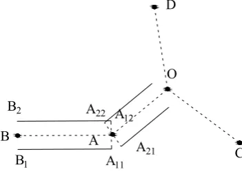
We will describe the integration modeling methods between single-tunnel and complex-tunnel in detail. For the integrated modeling between single-tunnel and complex-tunnel, we will discuss the example which seamless integration model is build between the trigeminal shaped tunnel (complex-tunnel) and single-tunnel. As shown in Fig.4, the dotted line AB is centerline of single-tunnel, it belongs to type of PART-ONE. The dotted line AO, CO, DO represent the center lines in three branches of trigeminal shaped tunnel, O is crossing node. It is type of PART-TWO. In Fig.4, the solid line is the side line of tunnel, assuming the position calculated in the figure, and if it is not processed, the case will appear as shown in Fig.5.that means the node A12 and A22, A11 and A21 can not overlap in two-dimensional environment. So the completion of three-dimensional tunnel is not continuous overall. Therefore, the paper proposes two solution methods, namely the method of mid-point interpolation and directed method of two-node.
A. Midpoint Interpolation Method
Midpoint interpolation: According to analytic geometry, a number of points on a same straight line have the same azimuth. That is the slope of line, if we know the three-dimensional coordinates of two points, the three-dimensional coordinates of mid-point can be obtained after calculation. Then, two points and mid-point are in the same straight line, it ensures that their position will not change.
A B
B1
B2
A11
A12
A
O
C D
A21
A22
Fig. 4. Models after subdivision
A
O
C D
B B1
B2
A11 A12
A21 A22
Fig. 5. Discontinuous composed model of tunnels
The specific processing steps are as follows:
Step1: Obtain the three-dimensional coordinates of every tunnel’s center line.
Step2: Subdivide the whole tunnel network, get the skeleton information of PART-ONE and PART-TWO.
⎪ ⎩ ⎪ ⎨ ⎧
+ =
+ =
+ =
2 / ) (
2 / ) (
2 / ) (
2 1
2 1
2 1
z z z
y y y
x x x
m m m
(1)
Step3: If the node to be inserted is in the PART-ONE, that is chosen in arc which connects the PART-ONE and PART-TWO. On the assumption that this arc is Arc1, the two nodes are N1(x1, y1 , z1) and N2(x2, y2, z2), the mid-point Nm can be solved by using (1). Therefore, the arc is bisection, the part which is adjacent to PART-ONE is also belong to PART-ONE, the other half belongs to PART-TWO, the models of PART-ONE and PART-TWO which are constructed would organically connect. Because of the same direction, the models are combined together seamless. As shown in Fig.6(a), before interpolation, the dotted line is boundary of PART-ONE and PART-TWO, after interpolation, the arc N1N2 is split, Nm is mid-point of arc N1N2, the dotted line(split line) has changed, that is the spilt line moves to Nm, the arc N1Nm belong to PART-ONE, NmN2 belong to PART-TWO, as illustrated in Fig.6(b). After partition, the tunnel model to be built would be integrated seamlessly.
PART-TWO PART-ONE
B A
O
N2
N1
N1 Nm N2 O A B PART-ONE PART-TWO
(b) After interpolation
Fig. 6. Interpolation of first case
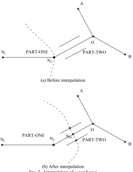
Another situation is to spilt the arc, which is within PART-TWO, connects with PART-ONE. Assumed that the arc has two nodes, which are O (the intersected node) and N2, as Fig 7(a) shows. We can still use the (1) to calculate the three-dimensional coordinates of Nm. It is different from above case that the arc can be subdivided into two new arcs within PART-TWO, one is N2Nm which is classified to PART-ONE, the other is NmO which is still belong to PART-TWO, as shown in Fig.7(b). The three-dimensional coordinates of Nm can be solved by using (1). Nm is the tail node of tunnel line N1N2Nm, Nm is also a node of arc ONm in trigeminal-shaped tunnel. PART-TWO PART-ONE B A O N2 N1
(a) Before interpolation
Nm PART-TWO PART-ONE B A O N2 N1
(b) After interpolation Fig. 7. Interpolation of second case
As shown in Fig.7(a), before interpolation, the dotted line separates PART-ONE and PART-TWO, After interpolation, the arc N2O is spilt, Nm is mid-point of N2O, the dotted line(the spilt line) moves to Nm, N2Nm is classified to PART-ONE, NmO belongs to PART-TWO (Fig.7(b)), After partition, the tunnel model built would be integrated seamlessly.
B. Directed Method of Double Nodes
Directed method of double nodes: the principle of this method is similar to the mid-point interpolation method, two nodes can fix a straight line, the direction doesn’t change, it doesn’t require interpolation, we can use the known nodes to solve. Firstly, the intersected node in PART-TWO can be used to direct, it can calculate the coordinates of inflection points and corresponding points (Nr1, Nl1) in connection between PART-ONE and PART-TWO. Then, the node within PART-ONE, which is adjacent to PART-TWO, can be utilized to direct the branch of PART-TWO. it can calculate the coordinates of inflection points and corresponding points (Nr2, Nl2) in connection between PART-ONE and PART-TWO. Thirdly, in theory, Nr1=Nr2, Nl1=Nl2, it would achieve the model integration of PART-ONE and PART-TWO. The specific calculation steps are as follows:
Step1: The tunnel network is divided into PART-ONE and PART-TWO.
Step2: While it deals with PART-ONE, it need to add a node in the tail node of PART-ONE, this node is intersection node of PART-TWO. In PART-TWO, every branch of PART-TWO also requires to add a new tail node which is adjacent to connected node in PART-ONE.
Step3: In during of concrete computation, these nodes stored again are only involved in directional terms, they don’t reflect in the actual three-dimensional modeling. Formula is as follows (2), k1 represents the slope of BC, the coordinate of CL1is (xL1,yL1), k2 represents the slope of CO, the coordinate of CL2 is (xL2,yL2), the coordinate of CR1 is (xR1,yR1), the coordinate of CR2 is (xR2,yR2). In terms of (2), the coordinates of CL(xL,yL) and CR(xR,yR) will be obtained.
⎪ ⎪ ⎩ ⎪ ⎪ ⎨ ⎧ − + = − + = − + = − + = ) ( ) ( ) ( ) ( 2 2 2 1 1 1 2 2 2 1 1 1 R RC R RC R RC R RC L LC L LC L LC L LC x x k y y x x k y y x x k y y x x k y y (2)
Fig.8 is schematic diagram before node orientation, dotted line subdivides the PART-ONE and PART-TWO, ED, DC, CO, AO, BO is center line of tunnel, CL1and CR1 are two sides points which the node C is corresponding to in the PART-ONE, CL2and CR2are two sides points which the node C is corresponding to in the PART-TWO. These side nodes can be obtained by using (2). From Fig.8, if we don’t use the directed method of double nodes, the side lines of PART-ONE and PART-TWO can crack or overlap each other after integration, as shown in Fig.8.
CL2 C CR2 CL2 CL1 E O A B PART-ONE PART-TWO D
In Fig.9, for modeling of PART-ONE, the node O, which belongs to PART-TWO, will be used to calculate as an orientation node. Then, the coordinates of CR and CL will be received.
B A
CR
CL
D
PART-TWO
PART-ONE
O E
CL1
CR1
CR2
C CL2
Fig. 9. Directed method of double nodes in PART-ONE
In Fig.10, as modeling of PART-TWO, the node D, which belongs to PART-ONE, will be used to calculate as an orientation node. Then, the coordinates of CR and CL will be received. It is known by comparing Fig.9 with Fig.10 that the two parts of CR and CL should have same values. According to directed method of double nodes, the tunnel model built would be integrated seamlessly.
CL2
C CR2
CR1
CL1
E
O
PART-ONE
PART-TWO
D
CL
CR
A
B
Fig. 10. Directed method of double nodes in PART-TWO
C. Approach to Avoid Cracking: Uniform Height Method On The Arch
As it will occur to sharp turn in the intersection of tunnels, so that the elevation value was calculated distortion, the half-tunnel model can be higher or lower on the arch, it will make two corresponding half-tunnels not merge, i.e. cracking phenomenon will generate. In order to prevent this case happening, the paper puts forward the uniform height method, and it is an effective method to modify the arch data.
Arch uniform height method: there are discrete points which possess same type or locate in the same sequence on the arch, the height from discrete point to tunnel floor locks to a constant, this method can limit the height of discrete point from floor, rather than limit the elevation value. When the tunnel appears sharp turn, it will lead to the elevation out of actual seriously.
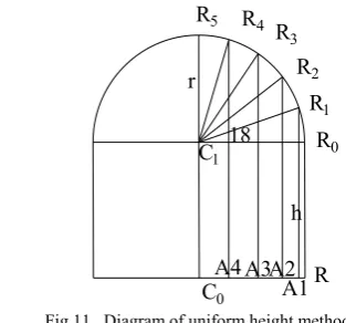
Fig.11 is a diagram of arch uniform height method. According to the idea of symmetric modeling, take the right half section for example, we will obtain five discrete points after 5 deciles (a discrete point every 18 degrees), such as R2, R3in the figure. If there is a sharp turn, the span of C1R0 will become large on the arch, the points’ coordinates of x and y is
correct, but the elevation values become large. It will result in distortion section, and make the two corresponding half-tunnel model cracking. In accordance with the uniform height method, take R1 for instance, the elevation of discrete point on the arch can be calculated by using (3).
C0 C1
R R0 R1
R2 R3
R4
R5
r
h 18
A1 A2 A3 A4
Fig.11. Diagram of uniform height method
0 sin( /10) 1,...,5
Ri C
z =z + + ×h r i×
π
i= (3)In the (3), Zc0 is elevation of C0, h is height of RR0, r is the radius of arch.
In order to avoid change of r in the tunnel intersection and turning, the value of r will be set as constant. During the modeling, r is a constant, because h is a constant too, (3) can be transforming into (4).
0
_
1,...,5
Ri C
z
=
z
+
Const i i
=
(4)Const_i is a height which the distance is from ith discrete point to floor on the arch, in any section, the discrete points, which locate in the same place of different arches, have identical height, namely Const_i. So, the heights from discrete points to floor are constant, for example, on section A, distance from discrete point located in R3 to floor is const_3, meanwhile, on section B, distance from discrete point lie in R3 to floor is also const_3.
In any section, the discrete points locate in R1, the height const_1 is a constant, similarly, when the discrete point lies in R2, the const_2 is a constant. It is the main idea of uniform height method. After amendment, the x and y coordinates of discrete points can’t be changed, their elevations can be computed by using (4). Thus, the cracking problem is solved in the sharp turn of tunnel intersection.
It is worth noting that the uniform height method applies only the tunnel section of same type in the field of tunnel 3D modeling. For instance, assuming that tunnel network exists just arch section, the uniform height method can be used to calculate the elevation of discrete points on the arch; if it has both arch tunnel and trapezoidal tunnel, we can use two different types of uniform height, one is utilized to compute the arch section, the other is used to determine the trapezoidal section of tunnel.
IV. CONCLUSION
subdivided into PART-ONE (composed of single-tunnels) and PART-TWO (constituted by complex-tunnels).
Step2: The models of PART-ONE and PART-TWO would be constructed respectively.
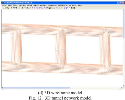
Step3: The 3D tunnel network model would be build by integrating the PART-ONE and PART-TWO. The tunnel models constructed by using above modeling methods are showing in Fig12. Fig.12 (a), Fig.12 (b) and Fig.12(c) are 3D models from different views. Fig.12 (d) is wireframe model of the part tunnel network.
(a)3D tunnel
(b) 3D tunnel model (from different views)
(c) 3D tunnel model after zoom in
(d) 3D wireframe model
We utilize Windows XP as the platform, MS Visual C++6.0 as development tools, and use OpenGL graphics package for the graphic processing function display tools, the experimental system of three-dimensional tunnel network modeling was designed and developed according to above mentioned methods (midpoint interpolation method, directed method of double nodes, arch uniform height method). Actual mining data are as instance, the experimental system has been tested, and it is shown that the paper verifies the practicality and effectiveness of research. The next work is that we will do more time for spatial analysis on the basis of 3D tunnel network model. It will give the make-decision for the mine production and mine safety.
ACKNOWLEDGMENT
The work described in this paper was carried out during on the author doctor’s degree in xi’an university of science and technology. The work was supported by a grant provided by National Natural Science Foundation of China (Project No.40972204), and partially supported by a grant of the Education Department of Shaanxi Province (Project No.2010JK682). The authors are grateful to the editors and anonymous reviewers more enough for their self-giving works.
REFERENCES
[1] K. Q. Yang, Z. L. Song, “The application of OpenGL in three dimensional display of laneway”, Journal of Lanzhou Polytechnic College, vol.11, no.2, pp. 8-11, 2004.
[2] P. G. Chen, X. B. Liu, W.Z. Shi, “A method of 3D modeling based on QTPV in subsurface rock bedding”. Journal of East China Institute of Technology, vol. 27, no. 1,pp. 73-78. Jan, 2004.
[3] Z. Y. Wei, B. S. Wang, Q Y. Li, “Underground laneway modeling and realization by C~(++)”. Editorial Board of Geomatics and Information Science of Wuhan University, vol. 30, no.7, pp. 650-653, July, 2005. [4] H. M. Zhang, Y. Sun, D. Guo, “Implement of the 3D virtual mine
system based on OpenGL”. Science Technology and Engineering, vol. 7, no. 4, pp. 643-645, 2007.
[5] K. Sun, Z. P. Weng, Z. T. Zhang, “3D Roadway Modeling Method based on Restrained Triangulation”. Mining Research and Development, vol. 27, no. 5, pp. 64-65, Sep, 2007.
[6] J. M. Wang, “The study of modeling and application in three-dimensional tunnel”, M.S.thesis, TaiYuan university of technology, TaiYuan, China, 2005.
[7] L. X. Wu, W. Z. Shi. Principles and Algorithms of GIS, China: Beijing: Science Press, 2003.
[8] Z. Q. Xu, B. R. Yang, L. G. Wang, “Laneway entity three dimensional modeling study and realization”. Computer Engineering and Applications, vol. 44, no.6, pp. 202-205, 2008.
[9] F. L. Wang, Y. B. Wang, “Research on the tunnel three dimensional modeling algorithm and virtual technology”. Journal of Hunan University of Science & Technology (Natural Science Edition), vol. 24, no.1, 91-94, Jan, 2009.
[10] C. Zhang, S. X. Dai, M. Huang, “Research and application of 3D geological and laneway integrated model”. Journal of Geomatics Science and Technology, vol. 27, no.1, pp.61-64, 2010.
[11] Y. L. Xie, Y. J. Wang, L. B. Yao, “Research on 3D laneway model and virtual interactive operation. Computer Engineering and Applications”, vol.45, no.23, pp. 231-235, Dec, 2009.
[12] J. H. Yao, “Modeling technology study on the three-dimensional laneway”. Journal of Taiyuan University of Science and Technology, vol.30, no.1, pp. 80-83, 2009.
[13] Z. H. Zhang, E. K. Hou, Z. Zhao, “An improved symmetrical modeling method on 3D tunnel modeling”, In: Proceedings of 2009 International Conference on Computer modeling and simulation, Macau, IEEE CS, Feb 251-256, 2009.
[14] Z. H. Zhang, E. K. Hou, Z. Zhao, “A new 3D tunnel modeling method-symmetrical modeling”, Metal Mine, no.5, pp. 34-39, May,
2009.
[15] Z. H. Zhang, “Research on Method of 3D Tunnel Network Modeling and Path Analysis”, Ph.D. dissertation, Dept. Geology. Eng. Xi'an University of Science and Technology, Xi'an, 2010.
Zhi-hua Zhang was born in Lingwu of Ningxia
Province in 1980. From 1998 to 2002, he was studied in the field of surveying and mapping engineering in Xi’an Mining Institute, and obtained bachelor’s degree; from 2003 to 2006, he was studied in the field of geology engineering in Xi’an University of Science and Technology, and obtained Master’s degree; from 2006 to 2010, studied in the field of geology engineering in Xi’an University of Science and Technology, and obtained doctor’s degree. In that time, his research direction was GIS and 3D Geo-science simulation.
He taught in Lanzhou Jiaotong University, and received lecturer qualification. He has taught VC++, OpenGL and so on. The main articles list: (1) Z. H. Zhang, E. K. Hou, Z. Zhao, “A new 3D tunnel modeling method-symmetrical modeling”, Metal Mine, no.5, pp. 34-39, May, 2009; (2) Z. H. Zhang, E. K. Hou, “Research on Three-dimensional Intersection Model between Vertical Shaft and Horizontal Tunnel”, Metal Mine, no.8, pp. 132-136, Aug, 2010. Current and previous research interests will focus on Digital City, 3D GIS.