e-ISSN: 2278-7461, p-ISSN: 2319-6491
Volume 7, Issue 5 [May 2018] PP: 46-54
Procedure for Technical Analysis of the Cause of Volvo FH 12
Road-Train Trailer Gearbox Failure
Ján Mandelík
11Department of Transport Safety, The University of Security Management in Kosice , Kosice, Slovak Republic
Corresponding Author: Ján Mandelík
Abstract:
The article deals with the Volvo FH 12 4x2 T 380 road-train trailer gearbox failure and technicalexpert's procedure to determine the cause of this failure. When operating the vehicle, the gearbox started to show signs in loss of functionality and then the vehicle was parked to service station. The gearbox failure led to a dispute between the owner of the vehicle and service station, that just sold the vehicle to the owner shortly before the failure, cause of the failure, what led to the agreement to determine the cause based on the damage analysis by technical expert, which had to assess whether the damage resulted from improper operating of vehicle by shifting a lower gear by the driver when driving downhill with a fully loaded road-train or by wear of the gear material. To determine the cause, the vehicle was serviced in the presence of a technical expert, and dismantling work was carried out according to his instructions. The result of investigation was to determine the course of failure´s origin of the gearbox in question.
Keywords:
road-train trailer, service station, gearbox failure, diagnostics, finding of damage cause--- --- Date of Submission: 21-05-2018 Date of acceptance: 05-06-2018 ---
---I INTRODUCTION
In practice, there are often cases, when service station and vehicle owner have a different opinion on the cause of vehicle failure. It is then the task of technical expert to assess and decide what caused vehicle to fail. The article deals with one of these cases, when Volvo FH 12 road-train trailer has repeatedly experienced a gear failure. The service station insisted that the gearbox failure resulted from the incorrect way of driver´s operation by shifting a lower gear while driving downhill with the fully loaded road-train. The owner of vehicle was of the opinion that despite the fact that technical lifetime of the gearbox was not run out, it was damaged due to the wear of its parts. Since there was a high repair cost in this case, owner and service station agreed to invite a technical expert to evaluate technical condition of gearbox and determine the cause of failure. For this reason, the technical expert proceeded as follow: the gearbox was inspected, dismantled, disassembled, the state of the oil filling was evaluated and, based on the results of these operations and their evaluation it has come to analyse an occurrence of the failure. All operations were documented by recording with the camcorder. The described technical expert´s procedure and his analysis of the identified damages is a valuable source for the work of other technical experts assessing similar cases, as it enables them to compare the nature of damages and the course of resulting analysis.
.
II VEHICLE DATA
vehicle type: tractor, T-N3-TN
make and type: VOLVO FH 12 4x2 T 380 engine type: Volvo D 12 A
full power in kW at rpm: 279/1800 engine cylinder capacity (ccm): 12,130 color: white
size and type of tires - 315/80 R 22.5 size and type of rims: 22.5 x 8.25 trailer weight: 31,980 kg
road-train weight: 40,000 kg Mileage: 531,653 km
The owner said that:
he noticed unusual sounds from the gearbox and vehicle was immediately parked. On Monday, a ride of about 3 km was made to a meeting with a service technician, followed by a test drive by service technician, and then the vehicle was transported to the service station by its own wheels, where damage was detected after the gearbox was removed and dismantled.
III INITIAL OPERATIONS
place: service station
findings on vehicle: mileage 631,653 km, vehicle without apparent damage to other groups
gearbox status at the time of the inspection:
Removed from the vehicle and disassembled - without housing, the gear system is fixed in the jig
Gearbox inspection findings: damaged two teeth of gear wheel of the 3rd gear shift of the spindle shaft and three teeth of gear wheel of the 3rd gear shift of the spline shaft
Photo documentation: video recording of inspection
Visual inspection:
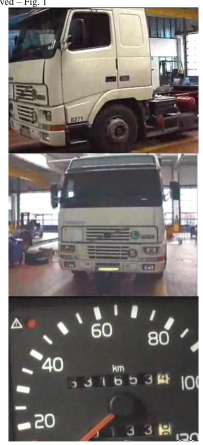
The vehicle and its engine were inspected in detail, as a result of which it was found that no incompleteness was observed – Fig. 1
Side view of Volvo FH 12 trailer
Front view of Volvo FH 12 trailer
View on the vehicle´s tachometer
The photo documentation from the gearbox inspection is in Fig. 2
view of the spindle gear shaft after removal from the gearbox housing
a closer look at the gear shafts with gear wheels
View of spline shaft gearing and marking of damages:
D1
D2
View of spindle shaft gearing and marking of damages:
P1
P2
View of fragments found in the gearbox
View of tooth fragments found
View of tooth fragments found
View of tooth fragments found
Fig.2 Photo documentation of the gearbox damage found
IV ANALYSIS OF THE FORCES ACTING IN GEARBOX GEARING
Fig.3 shows forces acting in gearbox gearing
When transferring forces with gear wheels act: - forces from the moment of rotation Mt = P /
- additional forces caused by engine run irregularities (external dynamic forces)
- additional forces caused by inaccuracy of the gear production and the change in stiffness of tooth during the engagement (internal dynamic forces)
Gear forces:
- peripheral force Fo = 2 . Mk / d - radial force FR = Fo . tg α - axial force FAX = Fo . tg β
- normal force FN = Fo / ( cos α . cos β )
Fatigue effects:
- contact fatigue - when calculating teeth, it is based on the baseline number of load cycles NHlim 50 to
10.106, which guarantees its lifetime as a whole - bending fatigue.
Note: The position of load changes during engagement. At the beginning of engagement, the load acts on head ring (F1) and ends up on foot (F3) see fig.3.
V CHARACTERISTICS OF D1, D2, D3 FRACTURE AREA AND P1, P2 FRACTURE AREA
Fig. 4, 5 shows views of the fracture areas
Fig.4 View of characteristics of D1, D2, D3 fracture areas
P1, P2
Fig.4 View of characteristics of P1, P2 fracture areas
VI CHARACTERISTICS OF FRACTURE AREAS OF BROKEN TEETH
Fig. 5 View of characteristics of teeth fractures areas 1,2 with an indication of fracture spreading - yellow arrow
VII COMPARISON OF FRACTURE AREAS CHARACTERISTICS
Fracture areas of the tooth 1 in area of Fragment A show a conchoidal relief with signs of gradual spread of the fatigue fracture from surface of the active tooth in the tooth engagement (in direction of the force acting) in area of the foot ring and then also down towards to the axis of the wheel. This characteristic of the fracture area is identical to
a characteristic of the fracture area in the area B of the tooth 2
Other parts of fracture of tooth 1 and tooth 2 correspond to the brittle fracture characteristics (grain, rough and rugged surface with clear microstructure of the material, with no marks and deformations)
Obr.6 View of characteristics of teeth fracture areas P2 (A), P1 (B)
VIII ANALYSIS OF THE COURSE OF FRACTURES OCCURENCE 1 st stage: occurence of fatigue fracture on tooth no.1 at fracture area A (P1)
Mentioned fatigue fracture with its characteristic of the fracture surface gives with the number of fatigue and relaxation lines assumption that its formation took place over a longer period of time, that it originated with plastic deformations in the fracture area and from the direction of line it is possible to derive its propagation direction (as shown) and the fracture area does not cross the engagement line.
2 nd stage: formation of brittle fracture on the tooth No. 1 outside of area A (P1)
After a time when the fatigue fracture propagation process in area A reached the limit of strength of the remaining tooth material, a brittle fracture of this material occurred (fracture of tooth out of the engagement line)
3 rd stage: : formation of brittle fracture on the tooth No. 2 in area B (P2)
Listed fatigue fracture with its characteristic of the fracture surface gives with the number of fatigue and relaxation lines assumption that its formation took place over a shorter period of time than the fatigue fracture on tooth No. 1 in the region A that its propagation direction is the same as the propagation direction of fracture in region A, the area of the fracture does not cross the engagement line.
4 th stage: formation of brittle fracture on the tooth No. 2 outside of area B (P2)
After a time when the fatigue fracture propagation process in area B reached the limit of strength of the remaining tooth material, a brittle fracture of this material occurred (fracture of tooth out of the engagement line)
5 th stage: formation of brittle fractures D1, D2, D3
These occurred as a consequence of tooth abruption due to subsequent impacts in the transmission of driving force in the plane of engagement line which was not smooth at any given time
IX CONCLUSION
Estimated start of fatigue fracture of the tooth 1 (P1) has been established for a longer period of vehicle operation until a fracture D1, D2, D3.
It follows that the failure of gearbox has not occurred due to improper handling of the vehicle by driver.
X ACKNOWLEDGEMENTS
The manuscript is not in conflict with any natural or legal person.
The presented research was funded by the author himself without any other support.
REFERENCES
[1]. FREIWALD A: Diagnostika a opravy automobilov I, (Diagnostics and repair of cars I),EDIS, 2004, ISBN 80-8070-267-5 [2]. VLK F.: Převodová ústrojí motorových vozidiel, (Transmision system of motor vehicles), Brno 2000, ISBN 80-238-8756-4