International Journal of Engineering Inventions
e-ISSN: 2278-7461, p-ISSN: 2319-6491
Volume 5, Issue 09 [Oct. 2016] PP: 18-24
Mechanical Analysis of Tungsten Based Micro-Hotplate
Structure
P. bhanja deo
Abstract:- This paper describes comparative study on stress distribution between micro hotplate designs of two types of micro hotplate. Here, micro- hotplate has been designed by taking metallic resistive tungsten as micro heater and is Silicon based. As micro hotplate plays an important role in the application of medical, laboratories, household like gas sensing ,micro heating ,infrared source etc. So, mechanically it should stable. Low cost tungsten has good mechanical strength and can operate reliably at high temperature (3000k), so it can be one good heater. Two different types of micro hotplate structures (membrane and micro bridge) are examined here, by taking the same dimension. Then, various micro hotplate configurations are designed and characterized. Parameters like: width of oxide layer and width of nitride layer over heater, and their effects on stress factor are also studied. Mechanical stress characteristics of the micro-hotplates are modelled, using COMSOL 4.2 simulator. This is a powerful finite element analysis simulator, which can be used in micro systems analysis.
Keywords: MEMS,𝑆𝑖3𝑁4 , Tungsten, micro-hotplate, membrane
I.
INTRODUCTION:
Micro-Electro-Mechanical Systems (MEMS) is the integration of mechanical elements, sensors, actuators, and electronics through micro fabrication technology, where electronic devices are fabricated using integrated circuit (IC) process sequences and range in size from micrometers to millimetres. So, MEMS technology helps in building complex machines on a micrometer scale by combining all types of physic and parts in one package. [1]
Using MEMS, it possible to reduce the device size, weight and cost as array of devices can be built on the same ground.
The objectives of the work are:
1. Design and simulation of a micro hotplate (based on tungsten) with two supporting beam. 2. Comparative study of micro-hotplate based on stress analysis.
1.1 Micro hotplate: Different types of micro hotplate have been used, where heaters are isolated either by a closed
membrane or by a micro-bridge. Micro-bridges are fabricated by a front side etch, while closed membranes are fabricated by back-side etching. [1, 2].In closed type membrane, where the membrane overlaps the silicon substrate along its periphery and in micro bridge-type membrane,
the membrane element is supported to the Si substrate by means of supporting beams, its central part being suspended over a cavity etched in the substrate. As [1] micro bridges offer better thermal
isolation, as heat can only flow through the bridge beams. However, they tend to be mechanically less stable, as they are supportedby only two beams and have a lower fabrication yield.[3]
Same rectangular geometry has been used in both two places for better comparison. Factors like substrate dimensions, hotplate dimensions and membrane thickness of micro hotplate and micro heater are kept constant.
Fig.2.1 Tungsten micro heater structure.
connection has been given at this two metal beam. This metal is also taken as the same tungsten and dimension is taken as 1×2 𝜇𝑚 .This two metal beams serves two problems (i) it gives mechanical supports to micro heater (ii) it can be used as supply electrodes. Here the range of temperature that we want is in between 300k-800k, where 300k is taken as reference temperature at the base of substrate. Then stress generated over oxide has examined.
2.1. Structure-1.
The structure-1 is a closed type membrane where the heater material and electrodes are kept within the dioxide layers with the backside of silicon substrate etched by isotropic etching process. Silicon substrate with a dimension of 600μm × 600μm in 𝑥𝑦 plane is taken and a cavity of 500μm × 500μm is generated.
Fig.2.2 tungsten micro heater, micro bridge type, structure-1
Membrane of 500μm × 500μm is generated in 𝑥𝑦 plane and the insulating material used for this membrane is silicon dioxide with thickness of 8μm. It separates the micro heater from the substrate. Silicon dioxide serves here many purposes as it gives high efficiency in thermal isolation so as to minimize heat conduction loss, thermally isolates the active heating area from the rest of the device body.[4,5]
2.2Structure-2
The structure-2 is suspended type of membrane where the micro heater is placed over a cavity along with the dioxides. The cavity of defined size is made by front etching process. The cavity of size 500μm × 500μm in xy plane, with height of 250μm is created. This geometry gives minimum thermal expansion but high stress due to only two beam support. Here the deformations in the membrane will take place and also in the heating element, which is lying above the membrane.
The membrane composed of silicon dioxide layer is kept above and below of heater and has dimension of 150μm ×150μm in xy plane. The heater made up of tungsten is self heated by giving potential across its two end electrodes.Structure-2 is shown in fig 2.3.
Fig.2.3 tungsten micro heater suspended type, structure-2
The two metal electrodes give support to heater as well as to dioxide membrane. This type of arrangement gives more temperature rise than that of structure-1 with same potential. These values are used and later the thickness of dioxide is varied.
3. Mechanical analysis: 3.1. Introduction:
For taking the relation thermal strain can be stated as: Thermal strain = α(t2−t1)
Where α = co-efficient of thermal expansion. 𝑡2 = final temperature of body. 𝑡1 = initial temperature of body. Thermal stress due to this is = α(t2−t1) E
3.2. Thin plate theory:
As ,we have taken three basic micro hotplate structures in our present work which are in the range of micro scale, so heater thickness is taken as 1μm . The heater plate thickness is small as compared to the substrate, which is a bulk surface. The presence of stress in this bulk surface can be determined using thin plate theory. Brief analysis is done by taking some differential equation for determining mechanical behaviour of plate.
The basic assumptions are taken here for analysis:[7] The plate is flat.
Plate thickness is small as compared to substrate. Plate material is isotropic and homogeneous.
Deflection of the plate is considered as small. This assumptions based theory is called as Kirchhoff’s plate theory.
3.2.1. Strain and stress relation:
For a three dimensional body according to hook’s law , constitutive equation relates stress and strain. It defines the material behaviour in mathematical way.[6,7]
𝜀𝑥= 1
𝐸[𝜎𝑥− 𝑣(𝜎𝑦+ 𝜎𝑍)] ……..3.1 =1
𝐸[𝜎𝜀𝑦 𝑦− 𝑣(𝜎𝑥+ 𝜎𝑍)] ……..3.2 𝜀𝑧= 1
𝐸[𝜎𝑧− 𝑣(𝜎𝑥+ 𝜎𝑦)] …….3.3 Where E = modulus of elasticity
and v = poison’s ratio.
𝛾𝑥𝑦 = 1 𝐺𝜏𝑥𝑦, 𝛾𝑦𝑧 = 1 𝐺𝜏𝑦𝑧, 𝛾𝑧𝑥 = 1 𝐺𝜏𝑧𝑥
Where G = shear modulus
Relation between G and E can be taken as: 𝐺 = 𝐸
2(1+𝑣) …….. 3.4
3.2.2. Basic differential equation:
The equation for the bending rectangular plate in x and y directions gives plate equilibrium equations:
Bending curvature can be determined as: 𝑋𝑥 = −𝜕2𝑤
𝜕𝑥 2,
𝑋𝑦 = − 𝜕2𝑤
𝜕𝑦 2 ………3.5
Twisting curvature can be determined as: 𝑋𝑥𝑦 = 𝑋𝑦𝑥 = − 𝜕2𝑤
𝜕𝑥𝑑𝑦 Considering these two above equations, we have: 𝜀𝑥=−𝑧
𝜕2𝑤
𝜕𝑥 2 = 𝑧𝑋𝑥 ………3.6 𝜀𝑦=−𝑧
𝜕2𝑤
𝜕𝑦 2= 𝑧𝑋𝑦 ……… 3.7 And
𝛾𝑥𝑦= −2𝑧 1 𝐺
𝜕2𝑤
𝜕𝑥𝑑𝑦 = 2𝑧 𝑋𝑥𝑦 …..….3.8
From the hook’s k law three equations can be written as: (Taking normal stress component 𝜎𝑧 = 0) 𝜎𝑥= 𝐸
1−𝑣2
( 𝜀 𝑥 + 𝑣𝜀𝑦 ) ……..3.9 𝜎𝑦= 𝐸 1−𝑣2
( 𝜀 𝑦 + 𝑣𝜀𝑥 )
…..3.10 𝜏𝑥𝑦 = 𝐺(𝛾𝑥𝑦) ……3.11 Introducing the plate curvature: 𝜎𝑥= 𝐸𝑧
1−𝑣2
(𝑋𝑥 + 𝑣𝑋𝑦 )
= − 𝐸𝑧
1−𝑣2
𝜕2𝑤 𝜕𝑥 2 + 𝑣
𝜕2𝑤
𝜕𝑦 2 … … …3.12 𝜎𝑦= 𝐸𝑧 1−𝑣2
( 𝑋𝑦 + 𝑣𝑋𝑥 )
= − 𝐸𝑧
1−𝑣2(
𝜕2𝑤 𝜕𝑦 2 + 𝑣
𝜕2𝑤
𝜕𝑥 2 ) ………3.13 𝜏𝑥𝑦 = 1−𝑣 𝐸𝑧 ( 𝑋𝑥 𝑦 )=− 𝐸𝑧
1+𝑣
𝜕2𝑤
𝜕𝑥𝜕𝑦 ………3.14
By taking the values of 𝜎𝑥 , 𝜎𝑦 and 𝜏𝑥𝑦 from equation and integrating over plate thickness we have, resultant stress in terms of curvatures and deflection:
𝑀𝑥 =D(𝑋𝑥+𝑣𝑋𝑦) = -D( 𝜕2𝑤
𝜕𝑥 2 + 𝑣
𝜕2𝑤
𝑀𝑦 = D(𝑋𝑦+𝑣𝑋𝑥) = - D( 𝜕2𝑤
𝜕𝑦 2 + 𝑣
𝜕2𝑤
𝜕𝑥 2 ) 𝑀𝑥𝑦 =D(1 − 𝑣𝑋𝑥𝑦)=D( 1 − 𝑣)
𝜕2𝑤
𝜕𝑦𝑑𝑦
Where D = 𝐸
(1−𝑣2)ℎ
3
D is the rigidity of plate.
Using the above equations we get stress as: 𝜎
𝑥= ±12𝑀 ℎ 3 ( 𝑥 𝑧 ) 𝜎𝑦= ±12𝑀
ℎ 3
( 𝑦 𝑧 )
𝜏𝑥𝑦 .=12𝑀𝑥𝑦
ℎ3 𝑧
4. Simulation and results:
The thermal stress can be observed by taking the structures under heat. Here the heat source is taken as the potential of 0.5v and gradually varying its value, different thermal stress values are taken. Using joule heating and thermal expansion physics under structural mechanics of COMSOL all the three structures are simulated by taking proper inputs material parameters such as young modulus, poison’s ratio and co-efficient of thermal expansion .
Boundary conditions applied to the structures for mechanical analysis are:
(1)The substrate base and the heater beams are made fixed with an initial displacement of zero. (2)The substrate base is kept at an ambient reference temperature of 300k.
4.1. Stress distribution:
All the three structures are simulated by fixing the beam end to the substrate. As tungsten is taken as the heating element, all the mechanical properties constraint has been taken. Thermal stress is due to heat generated, so stress is maximum that’s in contact with the heater. As we can see the thermal stress in case of closed type membrane is lower in compared to suspended type. Stress distribution is concentrated within the active area. All the stress observed are over the oxide layer. In case of structure-1 maximum value of stress obtained is 107Mpa and in case of structure-2 the maximum stress value reaches at 655Mpa at the constant supply of 0.5v.
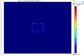
Fig 4.1 Shows stress distribution over oxide layer of structure-1 with thickness of oxide is 10μm(without nitride) and giving supply of 0.5v.
Fig 4.3 Shows stress distribution over nitride layer of structure-1 with nitride layer thickness is 3μm and giving supply of 0.5v.
Fig.4.2 and 4.3 shows stress results for structure-1 with nitride layer of 3μm, on the top of the entire oxide and also on the top of nitride layer. Fig.4.5 and Fig.4.6 shows stress results for structure-2 with nitride layer of 3μm, over oxide and also over nitride. We can observe that by application of nitride layer over silicon, the stress distribution over the silicon is lower and most of the stress is located at the nitride oxide boundaries at its maximum value.
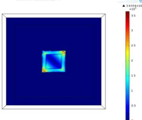
Fig 4.4 Shows stress distribution over oxide layer of structure-2 with thickness of oxide is 10μm(without nitride) and giving supply of 0.5v.
Fig 4.5 Shows stress distribution over oxide layer of structure-2with thickness of nitride is 3μm, and supply of 0.5v.
Below plot 4.7 represents a comparative plot of maximum thermal stress of two structures with varying the voltage (0-0.5v) .It shows increase in voltage gives rise to stress in both structures. From this plot it is concluded that structure-1 is more mechanically stable and structure-2 is more unstable giving high value of stress.
Fig4.7. Shows a comparative plot of maximum stress distribution of two structures with supply of 0.5v
4.2. Thermal Expansion:
Thermal Expansion is an internal thermal strain caused by changes in temperature according to the following equation for the thermal strain:
Eth =α(T − Tref)
Where α is the coefficient of thermal expansion, T is the temperature in the active area, and Tref is the strain-free
reference temperature.[6,7]
It is the nature of material that when it is subjected to heat its kinetic energy will increase thus molecular movements’ takes place. And the space between the molecules will be non uniform, but the material will try to retain their shape with undergoing expansion. So, we can conclude material with high melting point is having lower thermal expansion.
Tungsten is having very high melting point of order of 3000K, and thermal expansion coefficient as 4.6𝐸−6 (𝑘−1) , so it can be used as a good conductor for heating element.
4.3. Increasing membrane thickness:
In this work variation of oxide membrane thickness is done and the effects in stress distribution has also studied. The effects of varying thickness of oxide layer render in varying stress. Increasing in oxide thickness from 4μm to 10μm gives falling in maximum stress .A comparison study has been carried out between two structures.
Fig4.8. Shows maximum stress distribution over oxide surface of two structures by increasing oxide thickness without nitride layer at supply of 0.5v.
Next, the effect of stress by putting nitride layer over oxide, also have been examined. Where, thickness of nitride is varied from 1μm to 3μm, over the oxide surface on top. Structures fabricated with nitride layers produce high stress as thickness goes increasing as for thicker nitride layer, tensile stress increases.[7] Hence this makes increase in stress over oxide.
0 100 200 300 400 500 600 700
0.1 0.2 0.3 0.4 0.5
m
axi
m
um
s
tr
es
s(
M
pa
)
structure-1
structure-2
voltage(v)
0 200 400 600 800
4 6 8 10
m
axi
m
um
st
ress
(Mpa)
structure-1
structure-2
Fig.4.9. Shows maximum stress distribution over oxide surface by increasing nitride thickness(1-3)μm ,at a constant supply of 0.5v.
II.
CONCLUSION
:This paper , shows the novel MHP’s performance by comparing two structures on mechanical ground. As, there are two causes of high thermal stress. The first is due to having different thermal expansion constant materials in the composite structure. The second is having a structure, which cannot expand when heated. As per the study we can say the thermal stress obtained in bridge-type is superior to that of obtained from suspended membrane type. And this stress is reducing if we go for increase in oxide thickness. But on another way, if we move for putting nitride layer over this oxide then due to tensile stress, stress at oxide-nitride boundaries increases. Also other geometrical variation of two structures has been done in order to have different mechanical results. As, we obtained by increasing oxide thickness, stress over oxide decreases. So, thicker membrane gives better mechanical stability. Thus for different application different optimal designs are used.
REFERENCES:
[1] Tungsten-Based SOI Microhotplates
[2] for Smart Gas Sensors by Syed Z. Ali, , Florin Udrea, IEEE, ‘JOURNAL OF MICRO ELECTROMECHANICAL SYSTEMS’, vol. 17, no. 6, december 2008
[3] The Novel Microhotplate: A Design Featuring Ultra High Temperature, Ultra Low Thermal Stress, Low Power Consumption and Small Response Time by Hasan , and Mona Zaghloul SENSORCOMM 2013 : The Seventh International Conference on Sensor Technologies and Applications.
[4] Novel design and characterisation of SOI CMOS micro-hotplates for high temperature gas sensors, P.K. Guha, S.Z. Ali , Sensors and Actuators B 127 (2007) pg(260–266).
[5] 4.Micro hot plate platform for chemical gas ssensors, by S.Semancik and R.E Cavichhi. Sensors and Actuators,B 77(2001), pg. 579-591.
[6] Thermal properties of suspended porous silicon [7] micro-hotplates for sensor applications by
[8] C. Tsamis, A.G. Nassiopoulou, A. Tserepi. Sensors and Actuators B 95 (2003) pg.78–82
[9] Thin Plates and Shells, Theory Analysis and Applications. Eduard Ventsel Theodor Krauthammer .The Pennsylvania State University , Pennsylvania
[10] The Theory of Plates and Shells by McGraw-Hill, 1964. 0
500 1000 1500
1 2 3
m
ax s
tr
es
s(
Mpa
)
structure-1
structure-2