Design and Optimisation of a Moving-Iron
Linear Permanent Magnet Motor for Reciprocating
Compressors using Finite Element Analysis
T. Ibrahim
1, J. Wang
2, D.Howe
4, N. M. Nor
41-4
Electrical and Electronic Department, Universiti Teknologi PETRONAS, Malaysia 1
2-3Electronics and Electrical Department, University of Sheffield, United Kingdom
Abstract-– The paper describes design and optimisation of a tubular moving-iron linear permanent magnet motor for reciprocating compressor using finite element. The four leading design parameters are optimised individually. To validate the process reaches an optimal design, two leading parameters are varied simultaneously. This is due to one parameter may influence other parameters. The linear motor is aimed to produce 88.5 W output power which is enough to operate household refrigerator compressor system. . To reduce material and manufacture cost, S trontium Ferrite and soft magnetic composite are used in this design.
Index Term– Permanent Magnet Machines, Soft Magnetic Composite, Finite Element Analysis, Linear Motor
I. INT RODUCT ION
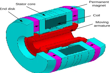
A comprehensive design optimisation for the leading design parameters of the moving-magnet linear motors have been described in [1] and [2]. However, the moving-magnet linear motors employ NdFeB permanent magnet which may also increase the material cost. The permanent magnets have to be circumferentially segmented in order to reduce the eddy current loss [3] where this process may increase manufacturing cost. Therefore, this research introduces an alternative design, moving-iron linear motor as shown in Fig. 1 for refrigerator compressor system. The motor is evolved from the original design of Evan [4] and employ relatively cheap permanent magnet material, viz., Strontium ferrite. The ring magnets mounted on the stator are easy to manufacture [4][5] and their resistivity is a few order of magnitude higher than that of NdFeB. Hence, eddy current loss in the magnets is negligible. Further, the moving-iron armature has a robust structure and may be optimised to have a lower mass which is conducive to improve dynamic capability of the compressor system [2].
The thrust force of linear motor can be enhanced by increasing the motor size, its magnetic loading and electrical loading. Due to the use of Strontium ferrite, which has a low remanence, the magnetic loading of the motor will be reduced. To achieve the same thrust force with satisfactory efficiency, the motor size i.e. the axial length and the outer radius have to be increased. Since the ring magnet are mounted on the stator, the required volume will be much greater than that of the moving-magnet designs. However, the
at the expense of reduction in motor efficiency when the available slot area is fixed.
Similar to the moving-magnet motor designs, the tubular stator core is made of soft magnetic composite (SMC) material, Somaloy 700, and carries a single coil. The use of an SMC material facilitates near net-shape, low cost manufacture, as well as good utilization of the available space to achieve a compact design. Also, the eddy current component of iron loss at the mains operating frequency of 50 Hz is negligible [7] due to very low conductivity.
End disk
Permanent magnet
Moving armature Coil Stator core
Fig. 1. T ubular moving-iron linear motor
Finite element technique is employed to optimise all leading design parameters of moving-iron linear motor. Although the technique is more time consuming compared to the analytical method, it is more accurate and can accommodate relatively complex geometries of the motor topology. The design optimisation is aimed to achieve maximum efficiency at the rated output power of 88.5 W subject to volumetric constraints.
II. OPEN-CIRCUIT FLUX DIST RIBUT ION AND BACK-EMF
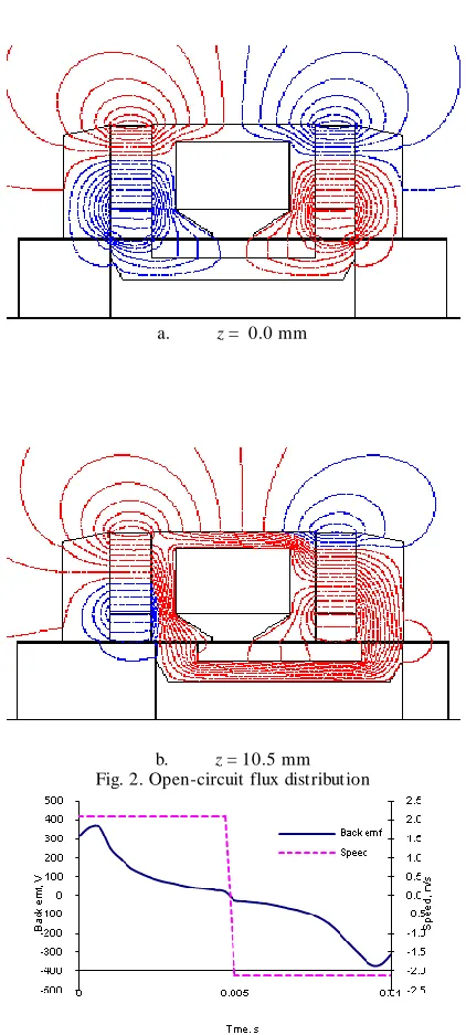
Figs. 2 (a) and (b) show the open-circuit flux distribution of an initial design at the initial position and maximum position respectively. At the initial position, the flux distribution is symmetrical with respect to the axial centre. Hence, the coil flux-linkage is zero. As the mover moves to the rig ht, the flux-linkage increases . However the rate of increase in the flux-linkage decreases as the mover displacement increases .
The mover moves from initial position at the constant speed and reaches the rate of stroke of 10.5 mm at t = 0.005 s. After this, the direction of movement is reversed, the mover return to the initial position at t = 0.01 s.
a. z = 0.0 mm
b. z = 10.5 mm Fig. 2. Open-circuit flux distribution
Fig. 3. Back-emf and constant speed of moving-iron linear motor
Fig. 3 shows the back-emf waveform for the moving-iron linear motor with a constant speed in both directions. The constant speed was chosen for illustration purpose. However, the sinusoidal speed will be used for the optimisation process in order to represent the actual operating condition. As will be seen from the back-emf waveform, the induced voltage decreases rapidly when the mover displacement is greater than 5.0 mm. This indicates that 10.5 mm stroke is not appropriate for this design, or in order to improve performance for the required stroke, the motor design needs to be optimised.
III. MET HODOLOGY
The optimisation is based on achieving maximum efficiency produced by the motor. By neglecting the eddy current and friction losses, the efficiency of the motor is calculated by the following equation:
% 100 cu fe out
out
P P P
P
(1)
where Pout, Pfeand Pcuare output power, iron loss and copper
loss, respectively.
The average output power, Pout,over an electrical period of
T, is determined by:
dt t i t E T
P s
T T
out () ()
1 0
(2)
where ET(t) and is(t) are the instantaneous of terminal voltage
and motor current, respectively, obtained from finite element analysis.
The basic equation to quantify the copper loss is determined by
R i Pcu rms
2
(3)
where irms and R are the rms current and resistance of the
winding respectively. The winding resistance, R, can be determined by
2
2 c
a f
N S P
r
R (4)
where , r, Nc,Pfand Sa are the resistivity of copper at a
given temperature, the average radius of the coil, the number of turns, the effective slot area and the packing factor, respectively. As will be seen from equation (4, the resistance, R, is a function of the effective slot area, Sa, and the number
of turns, Nc. They may vary with design parameters .
In the Flux-2D post processor, iron loss can be calculated based on Bertotti model using transient magnetic field solution over a specified electrical period. In order to quantify the iron loss, Pfe, hysteresis losses coefficient, kh, and excess
loss coefficient, ke, need to be identified. For the SMC
material, Somaloy 700, conductivity, , is set to zero and the coefficients of kh and ke are determined from the
IV.DESIGN OPT IMISAT ION
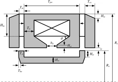
Fig. 4 shows the schematic and design parameters for the moving-iron linear motor. The relevant variables and symbol are defined as follows:
Symbol Description
Stator tooth tip under cut angle b0 Slot opening
G Air-gap
Hrt Thickness of armature tube
Htr Height of armature tooth
Hm Height of permanent magnet
Hst Height of stator tooth tip
Ra Outer radius of armature
Re Outer radius of stator
Trt Width of armature tooth
Tw Width of stator tooth
Tex Stator end disk
Tbe Width of armature tube cut
Hte Height of stator top edge cut
Tm Thickness of permanent magnet
Tpw Tooth pitch width
In the above 16 design parameters, Hst, Tbe, Hte and have
insignificant influence on the motor performance and therefore, their values are fixed to 1.0 mm, 2.0 mm, 2.0 mm and 30°, respectively. Although the force capability of the motor increases as the air-gap length decreases, its minimum value is limited by manufacture and assembles tolerances. In this design study, the air-gap length, G, is fixed to 0.8 mm.
In order to achieve satisfactory performance, the outer radius of the stator, Re, and the thickness of permanent
magnet, Tm are increased to 55.0 mm and 10.0 mm,
respectively. With the axial length of the stator core Tpw being
the same as the moving-magnet designs, the total axial length of the stator, including the two SMC disks at both ends, has been increased to a 90.0 mm. The resulting motor size represents the maximum available volume for a typical refrigerator compressor.
The thickness of armature tube, Hrt, the width of stator
tooth, Tw, and the thickness of the stator back-iron are
determined by the maximum permissible flux density in order to avoid high level of saturation in SMC material. The maximum permissible of flux density is set to 1.15 T which is close to the knee point of the Somaloy 700 B-H curve.
The thickness of stator end disk, Tex, also need to be
determined in order to provide sufficiently permeable path for the coil flux when the armature is at the maximum stroke as shown in
Fig. 2 (b). The thickness should be closed to the width of the armature tooth, Trt. This is to avoid the flux travels to a large
air-gap which may reduce the motor performance. In this design study, Tex is initially set to 11.5 mm.
Re z Htr Tpw Tw Tm Hm Ra Tbe Hte Hst Tex Trt Hrt G b0
Fig. 4. Schematic and design parameters of a tubular moving-iron motor
Thus, the leading design parameters which have significant influences on the motor are:
i. Width of armature tooth, Trt
ii. Height of armature tooth, Htr
iii. Ratio of Ra/Re
iv. Height of permanent magnet, Hm
The initial design dimensions and the specified operating conditions are illustrated in
TABLE I. The design optimisation of the linear motor is aimed to achieve the maximum efficiency at the rated output power, i.e., Pspec = 88.5 W under the volumetric constraint.
The optimisation is initially undertaken with a fixed peak value of motor current, I1, and assuming sinusoidal armature
velocity at 50 Hz and the rated stroke, and the resulting output power will vary as design parameters change. In order to obtain the same output power, Pspec, for a given set of
design parameters, and by assuming the output power is proportional to the motor current, the motor current, Inew
which yields Pspec, is adjusted using the following formula:
1 1
I P P
Inew spec (5)
With the new current, Inew, the motor performance is
calculated again. Fig. 5 shows the variation of initial and adjusted motor current with height of the armature tooth. The resulting output power are shown in
Fig. 6 as will be seen, with the fixed peak current of 0.5 A, the output power varies slightly with the design parameter and is below the rated value of 88.5 W. Thus the motor current has to be increased proportionally. With the adjusted current values, the efficiency of the motor is evaluated by finite element simulations, and results are shown in
T ABLE I
INIT IAL DIMENSION AND OPERAT IONAL CONDIT IONS
De scription of parame te r Value Units
Air-gap, G 0.8 mm
Height of armature tooth, Htr 5.0 mm Height of stator tooth tip, Hst 1.0 mm Outer radius of armature, Ra 20.0 mm Outer radius of stator, Re 55.0 mm
Stator tooth tip under cut angle, 30 ° T hickness of armature tube, Hrt 6.0 mm T hickness of permanent magnet,
Tm
10.0 mm
T ooth pitch width, Tpw 40.0 mm Width of armature tooth, Trt 10.0 mm
Width of stator tooth, Tw 6.0 mm Output power, Pout 88.5 W
Rated armature stroke, Xm 10.5 mm
Rms voltage supply, Vrms 230.0 V
Frequency, f 50.0 Hz
Stator core material Somaloy 700 - Remanence of St rontium ferrite,
Brem
0.396 T
A. Influence of width of armature tooth, Trt
The width of armature tooth, Trt provides the main path for
magnetic flux to flow from the stator to the armature. If the tooth is too narrow, the flux cannot path through easily to the armature, which reduces flux-linkage and motor efficiency. However, if the tooth is too wide, the saliency effect is reduced which affect the rate of change of flux, and results in a poor performance of the motor.
Fig. 5. Variation of motor current with height of armature tooth
Fig. 6. Variation of output power with height of armature tooth
Fig. 7. Variations of efficiency with height of armature tooth
With other leading parameters fixed to their initial values, the armature tooth width is varied from 9.0 mm to 11.0 mm and the resulting variation of motor efficiency is shown in
Fig. 8 as will be seen, at Trt = 10.0 mm, the motor produces
the maximum efficiency, 90.56 %. It should be noted that the optimal Trt coincides with the thickness of the permanent
magnet disk, Tm.
Fig. 8. Variation of efficiency with influence of width of armature tooth
Fig. 9 shows the variation of copper loss and iron loss with Trt. The iron loss includes the losses in the stator core, in the
two end disks, and in the moving armature. As can be seen, the iron loss increases slightly with Trt, while the copper loss
decreases with Trt. At Trt = 10.0 mm, the sum of the two loses
is at minimum.
Fig. 9. Variation of iron loss and copper loss with influence of width of
armature tooth
The armature tooth height has a significant impact on the performance of the motor. For example, if the armature tooth height is too small again the saliency effect is not significant which reduces the rate of change of flux and results in poor performance. If the armature tooth is too high, reluctance is increased which also leads to a low performance.
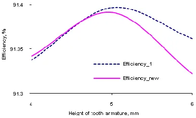
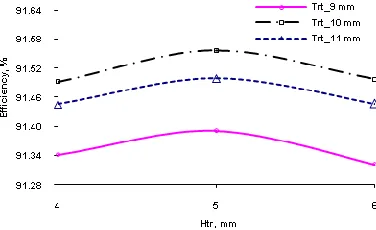
Fig. 10 shows the variation of motor efficiency with Htr,
when Trt is set to its optimal value of 10.0 mm, the other
parameters unchanged. The maximum motor efficiency, 91.56 %, occurs at Htr = 5.0 mm.
Fig. 10. Variation of efficiency with influence of the height of armature tooth
The iron loss decreases when the height of armature tooth increases as shown in
Fig. 11
,
this is due to the decrease in flux density in the stator and armature, as the reluctance increases. Meanwhile, the copper loss increases when the height of armature tooth is increased. This is because the motor current has to increase in order to provide the same output power.Fig. 11. Variation of iron loss and copper loss with influence of height of armature tooth
C. Influence of Ra/Re
The ratio of Ra/Re determines the balance between electrical
and magnetic loadings of the motor. This balance is important in order to achieve maximum performance. Increase in the outer radius of the armature, results in a great change of flux-linkage but reduces electrical loading since the slot area becomes less. In addition, the magnetic flux due to permanent magnets also reduces due to the reduction of the magnet volume.
Initially, the height of the magnet, Hm, varies with changes
of the inner radius of the coil as shown in Fig. 4 the Ra/Re
ratio is varied from 0.364 to 0.418 when Htr and Trt are set to
their optimal values. As will seen from Fig. 12, the maximu m efficiency,~ 91.60 % is obtained at Ra/Re= 0.4.
Fig. 12. Variation of efficiency with Ra/Re
The copper loss reduces slightly when the ratio of Ra/Re is
increased as shown in
Fig. 13 as Ra/Re increases although the slot area decreases
which tends to increase the motor resistance, th e coil flux-linkage and back-emf per turn increase. The motor current required to achieve the rated output power decreases. Thus, the combined effect results in very slight decrease in copper loss. The iron loss increases slightly when the ratio of Ra/Re is
increased. This is mainly due to the volume of the armature in which flux density varies rapidly as the armature moves is increased, resulting in a higher iron loss.
Fig. 13. Variation of iron loss and copper loss with Ra/Re
D. Influence of height of permanent magnet, Hm
Theoretically, increases the height of permanent magnet, Hm, will produce more output power and, hence better motor
efficiency. The disadvantage of this is that the cost of permanent magnet material will also increase. However Strontium ferrite is relatively cheap and the increase in magnet material cost is not significant.
Fig. 14 shows the variation of motor efficiency with the height of magnet, Hm, when Htr, Trt and Ra/Re are at their
optimal values. As will be seen, the motor efficiency continues to increase as Hm increase. However, the maximum
Hm value of 32.0 mm is limited by Ra/Re ratio, and the motor
Fig. 14. Variation of efficiency with height of permanent magnet
Fig. 15. Variation of iron loss and copper loss with height of permanen t magnet
Fig. 15 shows the variation of the copper loss and iron loss with the magnet height, Hm. The copper loss reduces when
the height of magnet increases. This is due to the reduction of motor current for the same output power. The iron loss increases slightly when the magnet height is increased due to increase in flux density in the stator and moving armature.
V. VALIDAT ION
The four leading design parameters are optimised individually using finite element analysis. However, one parameter may influence other parameters in term of optimal performance of the motor. In order to check if the above design process reaches an optimal design, two leading parameters varied simultaneously. As has previously stated, only three leading design parameters are considered for optimisation, i.e. width of armature tooth Trt, height of
armature tooth Hrt and the ratio of Ra/Re, and the height of
magnet, Hm varies with the inner radius of the coil.
Fig. 16 shows the variation of motor efficiency with Trtand
Hrt and other parameters being the same as stated in
TABLE I. As will be observed, the motor produces the maximum efficiency, 91.56 % at Trt = 10.0 mm and Hrt = 5.0
mm. This result Trt coincides with those obtained previously,
which implies the influence of one parameter on the optimal design on the other is insignificant.
Fig. 16. Influence of Trtand Htr on efficiency
Fig. 16 shows the variation of motor efficiency with Trtand
Ra/Re at the optimal value of Htr = 5.0 mm and other
parameters being the same as stated in
TABLE I. As will be seen, the optimal dimensions for Trt
and Ra/Re are 10.0 mm and 0.4, respectively, which yields
the maximu m motor efficiency of 91.6 %.
Based on the results shown in Figs. 16 and 17, the optimal dimensions of Trt, Htr, and Ra/Re are essentially the same as
those optimised individually.
Fig. 17. Influence of Trt and Ra/Re on efficiency
VI. CONCLUSIONS
Finite element technique has been used to optimise the design of the moving-iron linear motor. It has been shown that in order to achieve satisfactory efficiency, the volume of the motor has to be increased significantly. The efficiency of the moving-iron motor is satisfactory and still lower than the moving-magnet designs. However, its manufacturing cost is likely to be lower, since the permanent magnets have a simple shape, and will be easier for assembly.
REFERENCES
[1] T . Ibrahim, J. Wang, and D. Howe, "Analysis of a short -stroke, single-phase tubular permanent magnet actuator for reciprocating compressors," 6th International Sym posium on Linear Drives for Industrial Applications, LDIA2007, Lillie, France, September 2007. [2] T . Ibrahim, J. Wang, and D. Howe, "Analysis of a single-phase,
[3] J. Chai, J. Wang, and D. Howe, "Evaluation of eddy current loss in tubular permanent magnet motors by three-dimensional finite element analysis," Proceedings of XVII International Conference on Electrical Machines (ICEM2006), Paper ID: PSA1 -12, Chania, Greece, September 2006.
[4] S. A. Evans, I. R. Smith, and J. G. Kettleborough, "Permanent magnet linear actuator for static and reciprocating short stroke electromechanical systems," IEEE/ASME Transactions on Mechatronics, vol. 6 , no. 1, pp. 36-42, March 2001.
[5] Z. S. Al-Otaibi and A. G. Jack, "Utilising SMC in single-phase permanent magnet linear motors for compressor applications," 14th IET International Conference on Power Electronics, Machines and Drives, PEMD, York, UK, vol. 1, pp. 752-753, 2-4 April 2008.
[6] A. D. P. Juliani, D. P. Gonzaga, J. R. B. A. Monteiro, M. L. Aguiar, and A. A. Oliveira, "Magnetic field analysis of a brushless DC motor comparing ferrite and NdFeB magnets on rotor," Proceedings of IEEE Conference on Industrial Electronics and Applications ICIEA 2007, Harbin, China, pp. 260 - 264, May 2007.