e-ISSN: 2278-7461, p-ISSN: 2319-6491
Volume 6, Issue 12 [December. 2017] PP: 29-33
The research on optical method for determining amorphous
La
2O
3forbidden band width
Xiaojie Zhou
1 1School of Electronics and Information Engineering, Tianjin Polytechnic University, Tianjin 300387, China.
Abstract: The feature size of semiconductor devices is getting smaller, and the thickness of the traditional SiO2
layer is close to the limit of quantum tunneling under the progress of microelectronics technology. Therefore, the study of high performance of high-k materials is very important. The forbidden band width is an important parameter to study rare earth oxides as high-k gate dielectrics, and larger of forbidden band width, smaller of leakage current. In this paper, La2O3 is grown on Si(100) and quartz substrate on ultrahigh vacuum magnetron
sputtering equipment, and the forbidden band width of La2O3 is obtained through optical path proposed by Tauc
et al. The reliability of measuring La2O3 forbidden band width is verified by XPS. The experimental results show
that the forbidden band width of La2O3 measured by optical method is 5.15±0.2eV, and forbidden band width of
La2O3 measured by XPS is 5.10±0.15eV, the results of two ways are similar.
Keywords: Feature size, high-k gate dielectrics, XPS, forbidden band width.
---
---Date of Submission: 19-12-2017 ---Date of acceptance: 09-01-2018
---
---I.
Introduction
With the rapid development of the semiconductor industry, the feature size of the devices always follows Moore's law. That means the feature size of the devices is gradually decreasing, and the quality and function of IC(Integrated circuit) is improving greatly. At present, improving system performance of the integrated circuit mainly by reducing the size of devices, and it is related to the physical thickness of CMOS gate dielectrics. Once the thickness of the equivalent SiO2 gate dielectrics is less than 1nm, the edge value of
quantum tunnel breakdown will be achieved. Since the development of semiconductor industry, the thickness of SiO2 gate dielectrics has been reduced to the limit of electrons tunneling breakdown. If we reduce the thickness
of gate oxides later, it will lead to a sharp rise in leakage and power consumption, resulting in devices failure. Although 14Å or even smaller thickness of SiO2 insulation layer is available, the leakage current will
increase by 5 times for every 1Å of reduction of the SiO2 gate dielectrics, which make the use of SiO2 gate
dielectrics in the future difficultly. More importantly, many research groups have studied the ultimate thickness of SiO2, the physical thickness of the limit value is 7Å[1]. When the thickness of SiO2 less than 7Å, it will not be
able to guarantee original insulating properties, which means it will lose its status as a reliable gate dielectric materials[2-3]. In order to overcome the difficulty of gate dielectrics, we use high-k(the value of k is larger than the dielectric constant of SiO2) materials instead of SiO2
[4-6]
.
However, the size of k is not the only standard to examine the merits and demerits of high-k materials. Research shows the forbidden band width also plays a decisive role in two ways, one is the suppression of electron and hole tunneling probability, the other is providing a barrier height. Therefore, the measurement of forbidden band width becomes a necessary part of studying on the rare earth oxides as high-k gate dielectrics. Rare-earth metal oxides have many advantages such as high dielectric constant(~10-30) and wide forbidden band width(~5-7 eV) [7-9]. It has become an excellent materials for high-k gate dielectrics, especially La2O3 as the
most promising high-k gate dielectric materials in rare earth oxides.So the measurement of forbidden band width
is a necessary part of the study of rare earth oxides as high-k gate dielectric materials. The research on the forbidden band width of semiconductor materials is generally Tauc method, which is measured by ultraviolet visible spectrophotometer. The main process is to measure the transmission spectrum of the samples grown on the quartz substrate, and then use the Tauc formula to obtain the forbidden band width.
Several researches about determining forbidden band width of rare earth oxides have been reported[10-11]. S.A.Chambers et al. suggested that the band gap width of rare earth oxides can be determined by the difference of energy between the O 1s peak of X-ray Photoelectron Spectroscopy(XPS) and the starting positions of their energy loss peak[10]. Later, in another report, S. Miyazaki adopted XPS to measure the forbidden band width of some high-k gate dielectrics[11]. However, there is still a lack of verification to measure forbidden bandwidth of rare earth oxides.
www.ijeijournal.com Page | 30 La2O3 forbidden band width is obtained by the optical method proposed by Tauc et al, XPS is used to verify the
measurement of La2O3 forbidden band width reliability.
II.
Preparation technology and condition of La
2O
3thin films
2.1 Preparation technology
There are many ways to grow thin films, such as physical vapor deposition(PVD), chemical vapor deposition(CVD) and magnetron sputtering technology[12]. In all kinds of thin films deposition techniques, magnetron sputtering technology has been widely used because of low temperature and high speed[13].
Fig. 1 The principle of magnetron sputtering technology
The principle of magnetron sputtering technology is shown in Fig.1. We fill vacuum chamber with Ar, electrons collide with Ar in the process of accelerating toward the substrate under the action of the electric field, and then Ar ionizes to generate Ar+ and electrons. After that, electrons accelerates toward the substrate, Ar+ accelerates toward the cathode sputtering target and bombards the target surface with high energy to cause sputtering of the target materials, the neutral target atoms (or molecules) are deposited on the substrate to form films. In short, magnetic field changes the direction of electronic motion, binds and prolongs the motion path of electrons. As a result, it enhancing the ionization probability of electrons and effectively utilizing the energy of electrons.
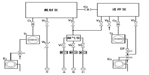
Fig. 2 Structure diagram of ultra-high vacuum magnetron sputtering instrument
the real-time measurement of the vacuum chamber and provides the necessary conditions for preparing the films. The minimum vacuum of the test is generally greater than 10-4Pa, and the pressure is generally required from 0.1Pa to 10Pa. The cooling water circulation system is mainly to prevent the mechanical pump and the high-speed operation of the molecular pump cause the overheating of the machine, but also to ensure that the thin films preparation process required room temperature conditions.
2.2 Preparation condition
La2O3 is grown on Si(100) by magnetron sputtering apparatus(JGP500D1) at room temperature, and we use P-Si
with 2-10Ω. In order to remove the effects of substrate and other sources of contamination, so as to make the thin films grow, we should clean the substrate thoroughly. The specific processing process is as follows:
1. Rinse deionized water
2. Ultrasonic 10 minutes for acetone 3. Rinse deionized water
4. Ultrasonic 10 minutes for deionized water 5. Ultrasound 5 minutes for alcohol
6. Rinse deionized water
7. Ultrasound 5 minutes for alcohol 8. Etching for 30 seconds of 10% HF 9. Nitrogen drying
Wash the substrate and seal it in place where the vacuum chamber is fixed. The vacuum of the thin films growth chamber reaches approximately 0.00027Pa and filled with Ar, control the pressure of sputtering about 1Pa. After the working pressure is stabilized, the sputtering target (La2O3 ceramic target with purity of
99.99%) is sputtered and the thin films is deposited on the substrate before the 10-15min is sputtered. In order to obtain a high quality thin films, annealing in O2 at 300°C for 30 min after deposition. At the same time, in order
to obtain accurate forbidden band width, La2O3 thin films on quartz substrate for optical test under the same
growth condition.
III.
Experiment and analysis
3.1 Optical method for measuring forbidden bandwidth of La2O3
The measurement of forbidden band width of La2O3 by optical method is based on the method which
put forward by Tauc et al[14], and it has been widely used. In the experiment, we test La2O3 on the quartz
substrate by UV-2550. We choose the UV-visible light source in the wavelength range of 150nm to 750nm, and collect the transmission and absorption spectra of the sample to analyze and calculate the specific forbidden band width[15-16]. It is reported that there is a connection between the absorption coefficient of UV-visible absorption spectrum and forbidden band width[17]
2
g
hv C hv E
(1) In the above formula, α is a absorption coefficient of ultraviolet spectrum, hv is a incident photon energy, C is a constant. In the meantime, we can measure the transmittance of the thin films that grow on the quartz substrate to obtain the specific absorption coefficients by combining the following equation[18]
ln T d
(2) where d is the thickness of the thin films and given by the test of ellipsometry. The corresponding absorption coefficient is calculated with equation(2) and then make a figure of (αhv)2 relative to hv. Combined with equation(1), it is found that when (αhv)2 is 0, Eg is equal to hv. Therefore, we make a linear extrapolation of the
changes of the obtained spectra to (αhv)2 to 0, and obtainEg of the materials.
www.ijeijournal.com Page | 32
Fig. 3 UV transmission spectra of La2O3/quartz substrate films
3.2 XPS for measuring forbidden bandwidth of La2O3
Next, we use XPS to calculate the forbidden band width of La2O3. The method of determining the
forbidden band width of high-k gate dielectrics by XPS spectroscopy has also been proved to be a successful and effective method. According to the principle of XPS mentioned above, we know that there are two types of energy loss during the escape process of X light, one is plasma excitation, the other is EV excited by electrons
and then EC. For these reasons,Egcan be obtained from the energy difference between the O 1s peak on the XPS
spectrum and the beginning of its energy loss peak.
In order to avoid the influence of the surface impurities on the test, we used the Ar+ etching method to make the sample surface of the mask to splash down about 2nm to collect the data. At the same time, in order to eliminate the interference of the substrate signal to the test result, a grazing incidence is used in the testing process, and the photoelectron take-off angle is 150°. Fig.4 shows the XPS spectra of the O 1s and O 1s energy loss peak of La2O3 thin films.
As shown in Fig.4, the process of determining the starting position of the O 1s energy loss using the linear extrapolation method. Combined with O 1s peak, it can calculate the difference between O 1s peak and the starting position of its energy loss peak, that means the forbidden band width value of La2O3 is 5.10±0.15eV,
and the relatively larger error is 0.15eV that is due to the wide and the weak energy loss peak strength of O 1s.
Fig. 4 XPS spectra of O 1s and O 1s energy loss of amorphous La2O3 films
In the end, table 1 shows the forbidden band width of La2O3 obtained by two methods, the result of XPS is
www.ijeijournal.com Page | 33
Table 1 The forbidden band width of La2O3 obtained by two methods
materials methods
optical(Eg) XPS (Eg)
La2O3 5.15±0.2 eV 5.10±0.15 eV
IV.
Conclusion
The La2O3thin filmsis grown on Si (100) by ultra high vacuum magnetron sputtering equipment, and the
filmsis tested after annealing. We also make a detailed description, its characterization technology is mainly XPS and UV-visible technology. Through analysis, we make a conclude.
The optical method is used to analyze the UV-visible light transmission spectrum of La2O3 films, and the
width of the forbidden band width of La2O3 is 5.15±0.2eV. The XPS method is used to analyze the O 1s and O
1s energy loss spectra of La2O3 films, and the forbidden band widthis 5.10±0.15eV. It can be proved that the
forbidden band width of La2O3 is accurate, and two methods to measure the forbidden band width of high-k gate
dielectrics are reliable.
References
[1] Muller D A, Sorsch T, Moccio S, Baumann F H, Evans-Lutterodt K, and Timp G. The electronic structure at the atomic scale of ultrathin gate oxides[J]. Nature,1999,399: 758.
[2] Tang S, Wallace R M, Seabaugh A, et al. Evaluating the minimum thickness of gate oxide on silicon using first-principles method[J]. Applied Surface Science, 1998, 135(1): 137-142.
[3] Muller D A, Sorsch T, Moccio S, et al. The electronic structure at the atomic scale of ultrathin gate oxides[J]. Nature, 1999, 399(6738): 758-761.
[4] Wang J J, Fang Z B, Ji T, et al. Band offsets of epitaxial Tm 2 O 3 high-k dielectrics films on Si substrates by X-ray photoelectron spectroscopy[J]. Applied Surface Science, 2012, 258(16): 6107-6110.
[5] Hibino T, Inoue T, Sano M. Electrochemical reduction of NO by alternating current electrolysis using yttria-stabilized zirconia as the solid electrolyte: Part II. Modification of Pd electrode by coating with Rh[J]. Solid State Ionics, 2000, 130(1): 31-39.
[6] Scarel G, Svane A, Fanciulli M. Scientific and technological issues related to rare earth oxides: An introduction[J]. Rare Earth oxide thin films, 2007: 1-14.
[7] Robertson J. Band offsets of wide-band-gap oxides and implications for future electronic devicess[J]. Journal of Vacuum Science & Technology B: Microelectronics and Nanometer Structures Processing, Measurement, and Phenomena, 2000, 18(3): 1785-1791. [8] Leskelä M, Ritala M. Rare-earth oxide thin films as gate oxides in MOSFET transistors[J]. Journal of Solid State Chemistry, 2003,
171(1): 170-174.
[9] Leskelä M, Ritala M. Rare-earth oxide thin films as gate oxides in MOSFET transistors[J]. Journal of Solid State Chemistry, 2003, 171(1): 170-174.
[10] Tauc J, Grigorovici R, Vancu A. Optical properties and electronic structure of amorphous germanium[J]. physica status solidi (b), 1966, 15(2): 627-637.
[11] Chambers S A, Liang Y, Yu Z, et al. Band offset and structure of SrTiO 3/Si (001) heterojunctions[J]. Journal of Vacuum Science & Technology A: Vacuum, Surfaces, and Films, 2001, 19(3): 934-939.
[12] Thornton J. Physical vapor deposition[J]. Noyes Data Corporation, Noyes Publications, Semiconductor materialss and Process Technology Handbook for Very Large Scale Integration(VLSI) and Ultra Large Scale Integration(ULSI),, 1988: 329-454.
[13] Nishikawa R, Satoyama S, Ito Y, et al. Magnetron sputtering apparatus: U.S. Patent 4,441,974[P]. 1984-4-10.
[14] Tauc J, Grigorovici R, Vancu A. Optical properties and electronic structure of amorphous germanium[J]. physica status solidi (b), 1966, 15(2): 627-637.
[15] Jianjun W, Ting J I, Yanyan Z H U, et al. Band gap and structure characterization of Tm2O3 films[J]. Journal of Rare Earths, 2012, 30(3): 233-235.
[16] Kraut E A, Grant R W, Waldrop J R, et al. Precise determination of the valence-band edge in X-ray photoemission spectra: Application to measurement of semiconductor interface potentials[J]. Physical Review Letters, 1980, 44(24): 1620.
[17] Hattori T, Yoshida T, Shiraishi T, et al. Composition, chemical structure, and electronic band structure of rare earth oxide/Si (100) interfacial transition layer[J]. Microelectronic Engineering, 2004, 72(1): 283-287.
[18] Tan T, Liu Z, Lu H, et al. Band structure and valence-band offset of HfO 2 thin film on Si substrate from photoemission spectroscopy[J]. Applied Physics A: materialss Science & Processing, 2009, 97(2): 475-479.