481
Abstract—This paper presents the application of DC-DC converter for supplying DC load from the standalone wind turbine. Output obtained from the induction generator is not constant due to variation in the wind speed. To maintain the constant voltage at the output step up converter and sliding mode based step down converter is used.
Index Terms—DC-DC converter , sliding mode control, wind turbine.
I. INTRODUCTION
In recent trend the utilization of renewable energy source for generation of electricity is increased due to pollution free operation. Wind is one of the important renewable source available in the earth. But the output obtained from the windmill is not constant due to variation in the wind speed. In this paper we take a standalone wind turbine to supply a DC load which operates in 400 V DC supply. To maintain the constant output at the load side sliding mode control (Step down) is used to switch the DC-DC converter. Here the output obtained from the generator is rectified using a diode bridge rectifier and the output of the rectifier is fed to the open loop step up converter. This converter operates with 50 per cent duty cycle (i.e. output is gets doubled). Output of the step up converter is fed to the DC-DC converter (step down) to maintain the constant output at the output. Step down converter used in this paper is a closed loop control and the firing pulse is generated using sliding mode control principle depending on the load voltage.
A. The proposed mode model:
The block diagram of proposed model is shown in fig 1.
Fig 1.Block diagram of proposed model.
B. Wind turbine and generator:
The MATLAB/SIMULINK model of wind turbine and generator is shown in the fig 3. Here the turbine block is
1 Institute of Road and Transport Technology, EEE Department, Erode, India (Email:[email protected]).
2 Institute of Road and Transport Technology, EEE Department, Erode, India(Email:[email protected]).
constructed using the look up table concept. The turbine characteristic also shown in fig 2. Synchronous generator is used as a exciter of induction generator. The advantage of using synchronous generator is whenever the wind speed is very low, power can be supplied from the synchronous generator which can be driven by the Diesel engine[1][2][3]. When wind speed is high synchronous generator can be used to excite the induction generator with zero power input.
Fig 2. Turbine characteristics
Fig.3 Simulink model of standalone wind turbine induction generator model
C. Rectifier and filter:
Here diode bridge converter is used to convert the ac to dc. The block diagram of diode bridge rectifier is shown in fig.4
Power Quality Analysis in Wind Power
Generation Using Sliding Mode Control
482
Fig 4.Simulink model of diode bridge rectifier
D. Step up Converter:
It is mainly used to step up the rectified output which help to maintain the constant output at the load side[2].
The output expression of step up converter is given by
δ
−
1
Vs (1)
Where
Vs - supply voltage
δ - Duty cycle
Duty cycle =
T
Ton
Fig 5. Simulink model of step up converter
Step up converter is operated with 50 per cent duty cycle. Now the output becomes doubled.
VO =2Vs (2)
E. Sliding mode control Based Step down Converter
The sliding mode control (SMC) has been proposed to improve the robustness and the dynamic response in DC-DC converter. The theory of SMC to DC-DC converter has been investigated in this paper. The SMC is a control approach, which complies with the nonlinear nature of DC-DC converter. This control technique offers several advantages compared to traditional control methods: Stability, even for large line and load variations, robustness, good dynamic response and simple implementation.
One of the most important features of the sliding mode regime in variable structure systems (VSS) is the ability to achieve responses that are independent of the system parameters, the only limit being the canonical form description of the system. From this point of view, the Buck DC/DC converter is suitable for the application of the SMC, since the Buck converter fulfils the statement: ‘‘the system is controllable if every state variable can be affected by an input signal’’. The output voltage and its derivative are both continuous and accessible for measurement. Before going
forward forapplying SMC to DC-DC converter, let us take a brief look on the theory of SMC.
II. SLIDING MODE CONTROL
Let us define the following control law:
(3)
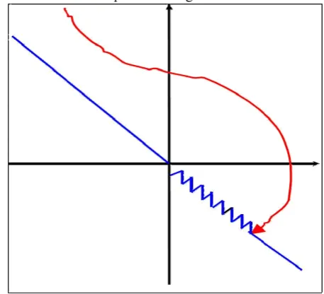
Where c is lower than q (system eigenvalues). The switching boundaries are then x2and the line x2+cx1. The system structure changes whenever the system representative point (P) enters a region defined by the switching boundaries[4]. The immediate consequence of this property is that, once (P) hits the switching line, the control law ensures that the (P) does not move away from the switching line x2+cx1=0, which is called the sliding line; the above discussion could be explained in Fig.6.
Fig.6 Sliding regime in VSS (switching line with hysteresis).
When sliding mode exists, the resultant system performance is completely different from that dictated by any of the substructures of the VSS. Performance can be, under particular conditions, made independent of the properties of the substructures employed and dependent only on the preset control law. (In this example the boundary x2+cx1=0). If the switching boundary is not ideal, i.e. the commutation frequency between the two substructures is finite, and then the overall system trajectory is as shown again in Fig. 1. If the width of the hysteresis around the switching line goes to zero, then the system behaviour returns to ideal. This phenomenon is called chattering. To have more detailed description of the properties of SMC, the reader should refer to [4].
III. SLIDING MODE CONTROL OF BUCK DC/DC CONVERTER
483 most DC/DC converters used in practice, the motion rate of the current is much faster than the motion rate of the output voltage. Using cascaded control structure with two control loops can solve the control problem: an inner current control loop and an outer voltage control loop. The voltage control is usually realized with standard linear control techniques, where as the current control is implemented using either PWM or hysteresis control. Here we use the sliding mode approach for the control of inductor current.
Fig.7.Cascaded control structure of DC/DC converter.
A. Simulation Model
Fig. 8. The simulation block diagram for the controller, controller includes the sliding mode current controller (inner loop in block) and the voltage
control loop
To construct the simulation model for the sliding mode controlled Buck converter, system model for the main power circuit has to be made. For the Buck converter, it is convenient to use a system description, which involves the output error and its derivative [4], i.e.
(4)
The system equations, in terms of state variables x1and x2,
and considering a continuous conduction mode (CCM) operation can be written as:
(5)
Where
v* : O/P voltage of the linear control.
u : Is a discontinuous input, which can assume the values 0 (switch off) or 1(switch on).
Direct implementation of the simulation model of the SMC-Buck converter can be derived from equations (4) & (5) and the control block diagram presented in Fig. 8.
IV. SIMULATION RESULTS AND DISCUSSION
A. .Turbine and Generator characteristics
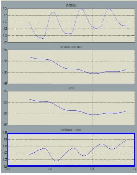
Fig.9 Turbine generator characteristics
In the fig.9 first characteristics shows stator flux of the induction generator. From the figure it is clear that the stator flux is constant by this type of excitation. Second one is mechanical torque input to the machine; third one is speed of the generator and forth one is electromagnetic torque developed by the machine. This simulation is done with the wind speed 12m/s.
B. Generator output
484
Fig 10 Generator output voltage
Induction generator output voltage is shown in fig.10. C. Rectifier output Voltage
Output of the induction generator is fed to the 3 phase diode bridge rectifier for rectification. The output voltage of the rectifier is shown in fig.11.
Fig. 11 output voltage of Diode Bridge Rectifier
D. Boost converter output
The output voltage of boost converter is shown in fig 12.from the figure it is clear that input voltage gets doubled which helps to provide the constant output voltage at the load side.
Fig 12.output voltage of boost converter
E. Load voltage
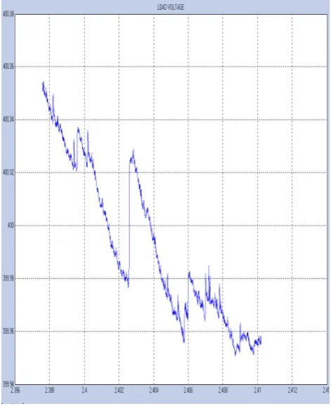
The dc output voltage of DC-DC converter (step down) is shown in fig.17. Here Dc reference voltage given to the converter is 400 V. From the fig.17 it is clear that output voltage is varied +.05V (or) -.05V from the reference value.
Fig. 13Load voltage
V. CONCLUSION
485 output of the induction generator. The SMC can be seen as an effective tool for controlling the DC-DC converter and the system behaves in a stable mode in steady state, also it can force the converter to stay in the stable mode due to large line and load variation. The SMC is an efficient and easy control algorithm that could be implemented in Matlab/Simulink and is gaining increasing importance as a control design tool in Matlab/Simulink for the robust control of linear and non-linear systems. Dc reference voltage given to the converter is 400 V. It is clear that output voltage is varied +0.05V (or) -0.05V from the reference value. Its strength results from the ease and flexibility of the methodology for its design and implementation. The control topology consists of a linear and non-linear part, and its left to the designer to tune the linear part depending on the application.
APPENDIX: Induction Machine Details:
OUTPUT : 275 KVA VOLTAGE : 480 V (L-L) FREQUENCY : 50Hz CONNECTION : Y
REFERENCES
[1] Dr.R.Anita “Modeling and simulation and analysis of DFIG for wind turbines” Journal of Electrical Engineering, Vol.60, No.2,2009 pp 79-85.
[2] M.M.Hussaini and Dr.R.Anita “ The Study of Dynamic Performance of Wind Farms with the Application of a STATCOM and its Effect” pp 158-160,IJJCE,Vol2 Nov.2009.
[3] R. Gagnon, B. Saulnier, G. Sybille, P. Giroux; "Modeling of a Generic High-Penetration No-Storage Wind-Diesel System Using Mat lab/Power System Block set" 2002 Global Wind power Conference, April 2002, Paris, France.
[4] B. Saulnier, A.O. Barry, B. Dube, R. Reid; "Design and Development of a Regulation and Control System for the High-Penetration No-Storage Wind/Diesel Scheme" European Community Wind Energy Conference 88, 6-10 june 1988, Herning, Denmark.
[5] L. Mott (NPS), B. Saulnier (IREQ) " Commercial Wind-Diesel Project, St. Paul Island, Alaska" 14th Prime Power Diesel Inter-Utility Conference, May 28-June 2, Winnipeg, Manitoba, Canada.
[6] Mohammad Ahmed “Sliding mode control for switched mode power Supplies” by. Lappeenranta University of Technology, Lappeenranta, Finland on the 14th of December 2004.
Mrs. M. Mohammadha Hussaini completed B.E in 1991 and M.E (Power Systems) in 1993 from Thiagarajar College of Engineering, Madurai with distinction. Published more than 7 papers in National Conference. Worked as Lecturer in Kalasalingam college of Engineering (1993-1995). Currently employed as Senior Lecturer in Electrical and Electronics Engineering Department in Institute of Road and Transport Technology, Erode since 1997.