Utilization of ZigBee Modules and MPLAB for RSSI Localization Applications
S.Dhanasekaran1, S.Reshma2, S.M.Sangeetha3 and R.Vishnu Prabha4
1Assistant Professor, Department of Electronics and Communication Engineering, Sri Eshwar College of Engineering, Coimbatore, Tamilnadu, India.
2,3,4UG Scholar, Department of Electronics and Communication Engineering, Sri Eshwar College of Engineering, Coimbatore, Tamilnadu, India.
Article Received: 27 January 2018 Article Accepted: 23 February 2018 Article Published: 10 April 2018
1. INTRODUCTION
Location estimation is one of the most common applications of wireless sensor networks (WSN). Data collected
within any WSN is often meaningless without information about the location in which it was collected. This
increases the need for node position information. Though nodes can have positions manually assigned to each
device, it would be more efficient if the nodes can determine their own locations. This is because a network usually
consists of hundreds of devices, and it would be a very tedious process to prepare each one with an individual
location. In order to determine the location, the nodes must possess some method to estimate the distance relative to
each other. There exists a variety of techniques to accomplish this, such as the inclusion of ultrasonic sensors and
laser scanners. To keep the nodes inexpensive, two methodologies are primarily used: time delay on arrival and
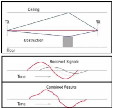
signal strength attenuation. There is one major factor that complicates distance estimation from wireless
transmissions - the multipath effect. The multipath effect is more prominent in indoor environments, however, it
exists in outdoor environment as well, but usually the signal scattering is more predictable. Time delay on arrival
techniques are less sensitive to this effect as they do not interpret distance from attenuation as signal strength based
techniques do. Fingerprinting techniques are used to determine location of a mobile node as it moves throughout an
area previously mapped with signal strength values. As the changes in signal strength are recorded as the node
moves throughout the map, probabilistic techniques are used to determine how the series of signal strength
observations correspond to locations within the map. This technique is incredibly sensitive to changes within the
environment, which requires tedious re-mapping if the radiation patterns changes. Therefore, it is more robust to
estimate distance from signal strength attenuation, however, multipath fading greatly affects these estimates and
some filtering or state estimation is usually required for indoor environment.
2. LOG-DISTANCE PATH LOSS MODEL
The signal strength attenuation is represented by received signal strength indicator (RSSI) in negative
decibel-milliwatts (-dBm). In free space, signal strength attenuates logarithmically with respect to the distance
A B S T R A C T
Localization is an important aspect for wireless sensor networks. Received signal strength indicator (RSSI) can be used to estimate distance between transceivers. Using these estimated distances, location of nodes within a network can be determined using various localization algorithms, such as trilateration. For implementation and testing of localization techniques, utilizing a sensor network development platform reduces time and difficulty during the process. Here we present a platform based on XBee ZigBee wireless modules, Arduino, and MATLAB for algorithm testing and debugging. For validation of this platform, a trilateration localization method is implemented.
between the transceivers. The most common models used to estimate the distance based on attenuation are the free
space propagation model and the log-distance path loss model.
Fig. 1. The effects of multipath on a receive signal
user finds need of watering the garden, a switch in the application will automate the process. This helps in complete
maintenance of the garden. In practical application, the latter is more reliable. This is because the former does not
account for any kind of offset from fading. The log-distance path loss model is especially useful for indoor
environment(though it can be used in outdoor as well) and is also a general propagation model. The model provides
a logarithmic attenuation model which has several parameters that can be tuned to make it fit within any
environment.
The RSSI (in dBm) for this model is expressed as:
RSSI = 10nlog10 (d) + A --- (1)
Where n is the path-loss exponent,
d is the transmission distance in meters,
A is the reference value,
A is taken as the RSSI at 1 meter away from the transmitter.
This equation can be rearranged to be expressed in as distance for a given RSSI value:
d = 10 RSSI−A 10n --- (2)
The path loss exponent(n) can be calculated for each environment by recording RSSI values at known distances and
reverse solving for n. The log-distance path loss model is the most versatile, as it can be configured for each
environment and also uses a reference value rather than requiring the transmission power and gain for each
transmitter and receiver. However, this model is still very susceptible to extreme multipath errors in highly
3. THE DEVELOPMENT PLATFORM
When testing RSSI localization algorithms, utilizing a development platform saves time in implementation and
debugging. However, existing WSN development platforms are expensive. Depending on the popularity of the
platform, the support may also be limited. To overcome these parameters, the development platform described here
has been designed with the overarching concept of selecting inexpensive components and software with a large
development community so that support would be readily available at all levels and modification of the existing
platform would be effortless.
A. Hardware Design
The radio module selected was the XBee series of wireless transceivers because it was inexpensive and versatile
enough to meet the desired specifications. The ZigBee series 2 modules were chosen for their low-cost and minimal
power requirements. They can also operate in the standard 2.4 GHz frequency range, which means that the
hardware could eventually build off of existing infrastructures as the XBee ZigBee uses the same protocol, IEEE
802.15.4, as many wireless routers. This particular module also uses directional antennas instead of
omnidirectional antennas. This is a very important feature as omnidirectional antennas are extremely expensive,
and chip antennas have poor propagation qualities. For the experiments covered in this work, XBee ZB radios were
used with Digi 2.4 GHz Omnidirectional Dipole antennas with a 2.1 dBi Gain. The XBee radios were configured as
routers with boost mode disabled and power level set to 2 (1 dBm Gain). One XBee was configured as the network
coordinator, and was connected to a PC for data collection. After selecting the radio module, the next step involved
finding the least expensive yet adaptable embedded programming board which could connect with the XBee. This
lead to the Arduino Nano along with its IO shield. Arduino Nanos are very cheap and its breakout board was
specifically designed for interfacing with XBees and similar wireless sensors. Overall, the hardware consists of the
following items for each node: Arduino Nano board, XBee ZB module, Arduino Nano IO shield. The case has openings for the battery cable from the battery to the Arduino board, an opening for the XBee’s antenna and one for
reaching the button of a battery should one exist. The case also has a lid which fits tightly to the base; this lid also
has a small window on it to see the LEDs on the Arduino board, which are programmed to flash indicating they are
properly transmitting or receiving data. The base is made to sit on a circular PVC pipe stand.
B. Node Firmware
The Arduino was selected not only for its low cost aspect, but also for the extensive XBee library available for it.
This library provides functions to interface the XBee through UART, packet creation, transmission, and reception.
By either pulling one of the GPIO pins high or low on the Arduino, the node’s functionality could be configured to
behave in two ways: mobile or anchor. Anchor nodes are used as the reference nodes with known locations. Mobile
nodes had unknown locations and would keep a list of all anchor nodes within range. Over a set period, mobile
nodes will query anchor nodes for the RSSI values. Anchor nodes would only respond to mobile node RSSI queries
with anchor node addresses and corresponding RSSI values back to the network coordinator, connected to a PC
running the MATLAB interface.
C. GUI Interface
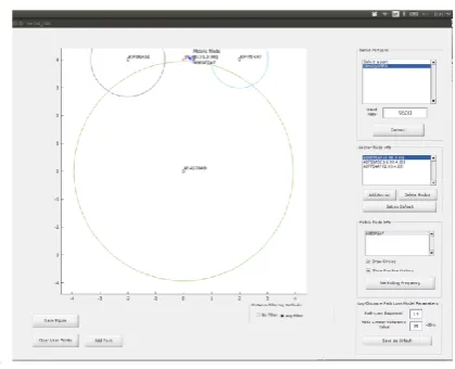
As humans are visual creatures, developing a visual reference utilizing MATLAB’s GUI editor was ideal for
indicating the estimated position of the mobile node graphically instead of simply with numbers as portrayed in
Figure 2.
.
Fig. 2. MATLAB GUI interface with WSN
This GUI served as a great debugging tool for actively visualizing where the mobile node was estimated to be. The
MATLAB GUI was designed to be scalable for any number of anchor and mobile nodes. Each anchor node would
require manual entry in the ”Anchor Node info” section of the GUI, by assigning the address an (x, y) coordinate.
Anchor nodes can also be modified by clicking on the saved address. Mobile nodes are automatically added to the ”Mobile Node info” list as new addresses are recognized. Mobile node addresses can be clicked to view
information such as which anchor nodes are within range and the RSSI values and estimated distance associated with each anchor. Figure 6 shows the mobile node’s list associated with Figure 5. The Log-Distance Path Loss Model Parameter” section allows the user to set the A and n parameters of the model from equation 2 for which the
distance is estimated. The GUI also allows the user to save the configurations for the anchor and path loss models as
default parameters for each time the application is loaded. Finally, the GUI provides the ability to average
localization results over time, show location history, draw circles around each anchor representing distance to the
currently selected mobile node, and plot and label points on the graph.
4. TRILATERATION IMPLEMENTATION
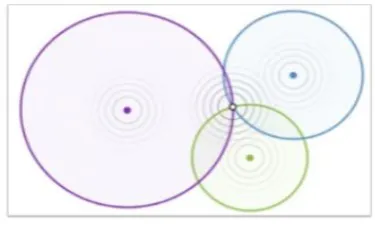
Trilateration is a method for estimating the location of an unknown point. It is calculated by the distance measured
to three or more known points. This technique is common in navigation for determining the position of a unknown
object. However, in order to account for uncertainty of the estimate, implementing trilateration using least squares
utilizing weighted nonlinear least squares (NLS) in the trilateration estimations, the weights of how each transceiver’s distance estimate contribute to the overall estimate of the unknown location.
Fig. 3. Depiction of trilateration method
In nonlinear least squares, the x,y location of the unknown point is set as function parameters for the euclidean
distance formula. Using the x,y positions of the known points and the measured distance to each of those points, the
nonlinear least squares algorithm finds the values of the x,y position of the unknown node which minimizes the
error between the calculated distance and the measured distance. The importance of each error is weighted by the
inverse of the measured distance squared, which is traditionally used in most radio-propagation based applications.
The nonlinear function model for NLS is given by the following
--- (3)
Where the βx and βy values are in the (x, y) position of the unknown point, xi and yi are the (x, y) position of the i th known point and ˆdi is the estimated distance to the i th known point.
---(4)
Where y is the measurement vector and di is the measured distance to the i th known point.
---(5)
Where W is the weights vector, and di is the measured distance to the i th known point
The Gauss-Newton method can be employed using the above equations and functions to iteratively solve for the unknown point’s position. Trilateration with NLS was the primary method for testing the developed tools. Outdoor
experiments using the free space RSSI-distance estimation model helped conclude that the tools worked within the
acceptable 1 meter variation range. Upon proof that the tools functioned, indoor experiments then helped conclude
which weighting method of the RSSI log-distance path loss model was best suited for the indoor environments
tested.
5. RESULTS AND DISCUSSION
The trilateration results demonstrate the unstable nature of distance estimation within a highly reflective indoor
environment. The outdoor trails gave an approximate resolution of 1 meter, which is the expected resolution when
using the log distance path loss model. The indoor trials had varying results due to the type of environment and
node positions within the environment. These trials also proved the usefulness of the development platform. Trials
were easier to conduct and debugging and identifying multipath interference was easier to observe with the
populated graph and circles representing estimated distance. It was also observed, that despite the XBee modules
utilizing carrier sense multiple access (CSMA) to avoid transmitting while the current channel is busy, the RSSI
value would experience interference if a delay was not enforced between anchor node readings. This was made
apparent during the outdoor trials where the 1 meter resolution was achieved with a delay, and the results were
highly erroneous without any delay or a very short delay between transmissions.
6. ACKNOWLEDGMENT
The authors would like to thank the volunteers who assisted with the experiment’s data collecting: Sam Knittel,
Colin Stewart, and Bryan Hollis. They also thank NC Space Grant for its financial support.
REFERENCES
[1] H. Balakrishnan, T. Supervisor, and A. C Smith, “The Cricket Indoor Location System, “Architecture, no.
2001, p. 199.
[2] P. Kułakowski, J. Vales-Alonso, E. Egea-Lopez, W. Ludwin, and J. Garc´ıa-Haro, “Angle-of-arrival localization based on antenna arrays for wireless sensor networks,” Computers and Electrical Engineering, vol. 36,
no. 6, pp. 1181–1186, 2010.
[3] A. Nasipuri and R. E. Najjar, “Experimental Evaluation of an Angle Based Indoor Localization System,” 4th
International Symposium on Modeling and Optimization in Mobile, Ad Hoc and Wireless Networks, 2006. [4] S. Lanzisera, D. T. Lin, and K. S. J. Pister, “RF Time of Flight Ranging for Wireless Sensor Network Localization,” 2006 International Workshop on Intelligent Solutions in Embedded Systems, pp. 1–12.
[6] “Multipath and Diversity.” [Online]. Available: http://www.cisco.com/c/en/us/support/docs/wireless-mobility/
wireless-lan-wlan/27147-multipath.html
[7] S. Shue and J. Conrad, “Development of a portable XBee C library and RSSI triangulation localization framework,” in 2014 11th Annual High Capacity Optical Networks and Emerging/Enabling Technologies
(Photonics for Energy), HONET-PfE 2014, 2014.
[8] A. Ahmad, S. Huang, J. J. Wang, and G. Dissanayake, “A new state vector for range-only SLAM,” Proceedings
of the 2011 Chinese Control and Decision Conference, CCDC 2011, pp. 3404–3409, 2011.
[9] B. Kim, W. Bong, and Y. C. Kim, “Indoor localization for Wi-Fi devices by cross-monitoring AP and weighted triangulation,” 2011 IEEE Consumer Communications and Networking Conference, CCNC’2011, pp. 933–936, 2011. [10] “Ultra Wide Band System - Trilateration - Control Systems Technology Group.” [Online]. Available: