VLC Based Indoor Blind Navigation System
A.Harini1, S.Deepika2, B.I.Blessy3 and Mr.M.Pravin4
1,2,3Student, Department of Electronics and Communication Engineering, Sri Ramakrishna Institute of Technology, Coimbatore, India.
4Assistant Professor (Sr. Gr.), Department of Electronics and Communication Engineering, Sri Ramakrishna Institute of Technology, Coimbatore, India.
Article Received: 01 March 2018 Article Accepted: 09 April 2018 Article Published: 28 April 2018
1. INTRODUCTION
Localization technique falls under three categories. They are 1) Global location system, 2) Wide-area location system and 3) Indoor location system. Indoor positioning is one of the exciting features of the wireless systems. Indoor location sensing uses a number of wireless technologies. This is because many real-time applications need the physical location of the object. Over years, lot of techniques has been used for sensing indoor locations and the problems have been addressed. Global Positioning system (GPS) is one of the famous indoor location sensing schemes. Since it is satellite dependent, it has a problem in locating the objects inside the building. The positioning accuracy is very low which could reach up to several meters. This is due to the incapability of the satellite microwave signals to pierce through the walls of the buildings. Later, the IEEE 802.11b wireless Ethernet standard is used widely for increasing applications in the indoor environment. This makes use of wireless communication. This technique is mainly used for robot localization. Sensors might be used for a team of robots or low-cost robot for localization. Measuring signal strength is the main operation of Ethernet localization. This would offer the main disadvantage of this process since it requires predicting.
LANDMARC is a location sensing prototype system to locate objects using Radio Frequency Identification (RFID) inside buildings. It has its own advantage of improving the total accuracy of locating objects by using the concept of reference tags. It is also feasible and cost-effective in sensing indoor locations. Automatic location sensing is a problem addressed in the emerging systems. To make RFID technology effective in indoor location sensing, three major features are added: triangulation, scene analysis and proximity. The well-known location-based system (GPS) is inefficient in determining the location of indoor objects as it is satellite dependent. The main intention is developing indoor location sensing system using easily accessible wireless devices so that existing infrastructures could be used. Infrared, 802.11, ultrasonic are some techniques that have their own advantages and disadvantages.
A B S T R A C T
The Visible Light Communication (VLC) has become promising for various wireless applications. VLC- assisted indoor positioning is aimed at providing guidance to the blind people due to its unique advantage of electromagnetic interference immunity and accuracy, instead of conventional wireless positioning system using radio frequency equipment. The blind people could use the system to locate the objects or places in an unknown indoor environment. A number of fixed transmitters and a moving receiver together contribute to the positioning process. The transmitter is fixed in the object or place which the blind people have to identify. A transmitter section consisting of a mode switch, microcontroller and Li-Fi transmitter, i.e., a number of photodiodes (PDs) that emits visible light continuously, send the pre-defined information of the object or place when the moving receiver section consisting of a Li-Fi reader, microcontroller, speaker comes in line of sight with the transmitter. The multiple PDs have no help from other fixed receiving nodes with known co-ordinates. The blind people carry the receiver. When the transmitter and the receiver syncs, the information fed in the Tx microcontroller is delivered to the reader which in turn stimulates the Rx microcontroller to trigger the proper voice output by switching on the voice recorded circuit, and send it through the speaker thereby helping the blind people to identify the object or place ahead of them.
The no contact and non-line-of-sight nature are the strengths of RFID along with remarkable speeds. It communicates between RFID tag and reader by means of storing and retrieving data through electromagnetic transmission to an RF compatible integrated circuit. RF tags are both active and passive but active tags have more range than passive tags.
Visible light has become promising for various wireless applications. In particular, visible-light communication (VLC) assisted indoor positioning enjoys its unique advantage of electromagnetic interference immunity and high accuracy. Instead of directly extending conventional wireless positioning using radiofrequency equipment, we consider the indoor positioning specified for a popular VLC scenario where the target device has multiple photodiodes (PDs) while having no help from other fixed receiving nodes with known coordinates. The system consists of two main parts: transmitter and receiver. White LED is used as the source of the transmitter. Pin diode is used as the receiver. Depending on the functionality of the above components and their performance, the wireless positioning systems can be made.
2. HARDWARE USED
2.1. PIC16F877A MICROCONTROLLER
The PIC16F877A belongs to a set of 8-bit microcontrollers of RISC architecture that belongs to family of Harvard architecture microcontrollers made by Microchip Technology. The integrated circuit (IC) containing both processor and peripheral devices (Timers, ADC, USART, EEPROM, I2C, SSP, PSP) that are built-in is called PIC microcontroller. Harvard architecture is a new concept than Von-Neumann architecture; it rose out of the necessity to speed up the work of a microcontroller. In Harvard architecture, both the data bus and address bus are separate. Microcontroller with Harvard architecture is called “RISC Microcontroller”.
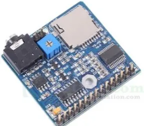
2.2. VOICE PLAYBACK MODULE
The voice playback chip is used to record the voice for some concern and play back the recorded voice for certain applications. The usual audio format is as usual so that it is very efficient. Wherever there is a use of pre-recorded voice is required, it plays a major role.
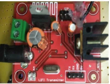
2.3. LI-FI
Figure 3. Li-Fi Receiver
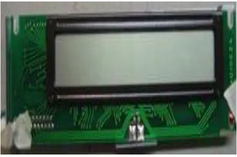
2.4. LCD DISPLAY UNIT
Liquid crystal displays (LCDs) have materials which combine the properties of both liquids and crystals. Rather than having a melting point, they have a temperature range within which the molecules are almost as mobile as they would be in a liquid, but are grouped in an ordered form together similar to a crystal. An LCD consists of two glass panels, with the liquid crystal material sand witched in between them. The inner surface of the glass plates are coated with transparent electrodes which define the character, symbols or patterns to be displayed polymeric layers are present in between the electrodes and the liquid crystal, which makes the liquid crystal molecules to maintain a defined orientation angle. One each polarisers are pasted outside the two glass panels. These polarisers would rotate the light rays passing through them to a definite angle, in a particular direction. When the LCD is in the off state, light rays are rotated by the two polarisers and the liquid crystal, such that the light rays come out of the LCD without any orientation, and hence the LCD appears transparent. When sufficient voltage is applied to the electrodes, the liquid crystal molecules would be aligned in a specific direction. The light rays passing through the LCD would be rotated by the polarisers, which would result in activating the desired characters.
The LCDs are lightweight with only a few millimeters of thickness. Since the LCD’s consume very less power,
they are compatible with low power electronic circuits, and can be powered for long durations. The LCD doesn’t generate light and so light is needed to read the display. By using backlighting, reading is possible in dark. The LCD’s have long life and wide operating temperature range. Changing the display size or the layout size is relatively simple which makes the LCD’s friendlier to the customers. The LCDs used solely in watches, calculators
Figure 4. LCD display
2.5. POWER SUPPLY UNIT
The operation of power supply circuits built using filters, rectifiers, and then voltage regulators is given here. Starting with an ac voltage, a steady dc voltage is obtained by rectifying the ac voltage, then filtering to a dc level, and finally, regulating to obtain a desired fixed dc voltage. The regulation is usually obtained from an IC voltage regulator unit, which takes a dc voltage and provides a somewhat lower dc voltage, which remains the same even if the input dc voltage varies, or the output load connected to the dc voltage changes. The ac voltage, typically 120 V rms, is connected to a transformer, which steps that ac voltage down to the level for the desired dc output. A diode rectifier then provides a full-wave rectified voltage that is initially filtered by a simple capacitor filter to produce a dc voltage.
This resulting dc voltage usually has some ripple or ac voltage variation. A regulator circuit can use this dc input to provide a dc voltage that not only has much less ripple voltage but also remains the same dc value even if the input dc voltage varies somewhat, or the load connected to the output dc voltage changes. This voltage regulation is usually obtained using one of a number of popular voltage regulator IC units.
2.6. MP LAB IDE
MPLAB IDE is a Windows Operating System (OS) software program that runs on a PC to develop applications for Microchip microcontrollers. It is called an Integrated Development Environment, or IDE, because it provides a single integrated "environment" to develop code for embedded microcontrollers. Experienced embedded systems designers may want to skip ahead to Components of MPLAB IDE. It is also recommended that MP LAB IDE On-line Help and MP LAB IDE Updates be reviewed.
3. PROPOSED WORK
The block diagram of the transmitter and receiver is as follows:
Transmitter:
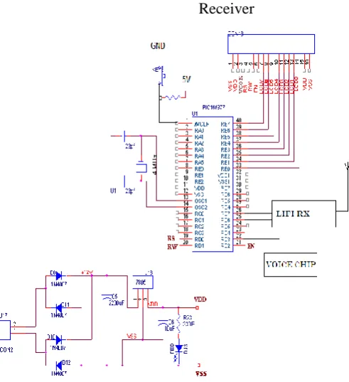
Receiver:
Figure 5. Block Diagram of Proposed system
The circuit diagram of the transmitter and receiver is as follows:
Transmitter
Mode
switch
PIC 16F877A
Microcontroller
Li-Fi
Transm
itter
PIC
16F87
7A
Power
supply
Li-Fi
Reade
r
Voice
alerts
Display
Receiver
Figure 6. Circuit Diagram of Proposed system
The system consists of the Li-Fi transmitter and receiver. The transmitter is fixed in the object or place which the blind people have to know about. A transmitter section consisting of a mode switch, microcontroller and Li-Fi transmitter, i.e., a number of photodiodes (PDs) that emits visible light continuously, send the pre-defined information of the object or place to the moving receiver section which consists of a Li-Fi reader, microcontroller, speaker comes in line of sight with the transmitter. The multiple photodiodes have no help from other fixed receiving nodes with known co-ordinates. The blind people carry the receiver. When the transmitter and the receiver syncs, the information fed in the Tx microcontroller is delivered to the reader which in turn stimulates the Rx microcontroller to trigger the proper voice output by switching on the voice recorded circuit, and send it through the speaker thereby helping the blind people to identify the object or place ahead of them.
4. APPLICATIONS
This navigation system is an application of Visible Light Communication. Some of the similar applications are 1. Hazardous places
2. Malls 3. Museums 4. Hospitals
5. Sending notes through VLC transmitter using available sources that could used by many receivers
5. ADVANTAGES
many receivers could receive the information at the same time from a single transmitter that shares information. This in turn reduces the cost and improves utility.
6. CONCLUSION
It is concluded that the system is used for helping the visually challenged people in any unknown indoor locations without the help of any other persons. This increases the self-confidence of the challenging people and paves a way for them to explore the world on their own. Moreover, it is helpful in behaving cost efficient and provides a good scope in further improvement so that it could be used by many people at same time. Hence the two systems: transmitter and receiver together is providing a beneficial result of meeting the objective.
REFERENCES
[1] Sherine Shawky, Mohamed A. El-Shimy, et al., “Improved VLC-Based Indoor Positioning System Using a Regression Approach with Conventional RSS Techniques,” IEEE Wireless Communications and Mobile
Computing Conference(IWCMC), 13th International, p. 904-909, 2017.
[2] Lionel. M. Ni, Yunhao Liu, Yiu Cho Lau and Abhishek P. Patil, “LANDMARC: Indoor Location Sensing Using Active RFID,” First IEEE International Conference on Pervasive Computing and Communication,
2003.
[3] Martin Vossiek, Leif Wiebking, Peter Gulden, Jan Wieghardt and Clemens Hoffmann, “Wireless Local Positioning – Concepts, Solutions, Applications,” IEEE Radio and Wireless Conference, RAWCON’03 Proceedings, 2003.
[4] Neal Patwari, Alfred O. Hero, Matt Perkins, Neiyer S. Correal, et. al., “Relative Location Estimation in Wireless Sensor Networks,” IEEE Trans. on Signal Processing, vol. 51, no. 8, p. 2137-2148, 2003. [5] T. Komine and M. Nakagawa, “Fundamental analysis for visible-light communication system using LED
lights,” IEEE Trans. Consum. Electron,vol. 50, no. 1, p. 100–107, 2004.
[6] Andrew M. Ladd, Kostas E. Bekris, Algis P. Rudys, Dan S. Wallach, et. al., “On the Feasibility of Using Wireless Ethernet for Indoor Localization,” IEEE Trans. on Robotics and Automation, vol. 20, no. 3, p.
555-559, 2004.
[7] Z. Xiang, S. Song, J. Chen, H. Wang, J. Huang and X. Gao, “A wireless LAN based indoor positioning technology,” IBM J. RES. & DEV. vol. 48, no. 5.6, p. 617-626, 2004.
[8] L. Hui, H. Darabi, P. Banerjee and L. Jing, “Survey of wireless indoor positioning techniques and systems,” IEEE Trans. Syst., Man, Cybern, vol.37, no.6, p. 1067–1080, 2007.
[9] T. Komine, J. H. Lee, S. Haruyama and M. Nakagawa, “Adaptive equalization system for visible light wireless communication utilizing multiple white LED lighting equipment,” IEEE Trans. Wirel.
Communication, vol. 8, no. 6, p. 2892–2900, 2009.
[11] Sridhar Rajagopal, Samsung Electronics, Richard D. Roberts, Intel Sang-Kyu Lim, ETRI, “IEEE 802.15.7 Visible Light Communication: Modulation Schemes and Dimming Support,” IEEE
Communications Magazine, vol. 31, no.1, p. 72-82, 2012.
[12] Hyun-Seung Kim, Deok-Rae Kim, Se-Hoon Yang, Yong-Hwan Son, and Sang-Kook Han, Member, IEEE, “An Indoor Visible Light Communication Positioning System Using a RF Carrier Allocation Technique,” Journal of Lightwave Technology, vol. 31, no. 1, p. 134-144, 2013.
[13] Jean Armstrong, Y. Ahmet Sekercioglu, and Adrian Neild, “Visible Light Positioning: A Roadmap for International Standardization,” IEEE Communications Magazine, vol. 51, no. 12, p. 68-73, 2013.
[14] Josline Priya Dsouza, Daya Naik, “Visible Light Communication using White LEDs for Indoor Wireless Data Transmission,” International Journal of Innovative Research in Electrical, Electronics,
Instrumentation and Control Engineering, vol. 3, Special Issue 1, p. 86-89, 2015.
[15] Wenjun Gu, Mohammadreza Aminikashani and Mohsen Kavehrad, “Indoor Visible Light Positioning System with Multipath Reflection Analysis,” IEEE International Conference on Consumer Electronics, p.