National Conference on Advances in Engineering and Applied Science (NCAEAS) 29th January 2018
Organized by : Anjuman College of Engineering and Technology (ACET) Nagpur, Maharashtra, India, In association with
International Journal of Scientific Research in Science and Technology
Improving Power Quality of Distribution Grid by Using Ultra
Capacitor
Zarmin Khwaja*, Farheen Zahra, Ibrahim Sheikh, Chandrashekhar Deshmukh, Sweta Sahare, Sumraan Sethiya, Diksha Pardi, Ruhi Sheikh
Department of Electrical Engineering, Anjuman College of Engineering and Technology, Nagpur, Maharashtra, India
ABSTRACT
Integration of Energy storage technologies into the power grid is slowly becoming a reality. So there is an increase in power quality problems on the grid. In order to improve the power quality of the distribution grid, an ultra-capacitor (UCAP) is proposed in this paper. UCAP have high power density and low energy density ideal characteristics for compensation of voltage sag and swell which are both high power and low energy event. The proposed paper integrates UCAP into dc-link of the power conditioner through a bidirectional dc– dc converter that helps in providing a stiff dc-link voltage. The simulation model of the overall system is developed and compared with the previous published work.
Keywords: Dynamic voltage restorer (DVR), Active power filter (APF), digital signal processor (DSP), ultra capacitors (UCAP), DC-DC Convertor.
I.
INTRODUCTION
POWER QUALITY is major cause of concern in the industry, and it is important to maintain good power quality on the grid. Therefore, there is renewed interest in power quality products like the dynamic voltage restorer (DVR) and active power filter (APF). DVR prevents sensitive loads from experiencing voltage sags/swells and APF prevents the grid from supplying no sinusoidal currents when the load is nonlinear. The concept of integrating the DVR and APF through a back–back inverter topology was first introduced in and the topology was named as unified power quality conditioner (UPQC). The design goal of the traditional UPQC was limited to improve the power
the distribution grid. Applications where energy storage integration will improve the functionality are being identified, and efforts are being made to make energy storage integration commercially viable on a large scale. Smoothing of DERs is one application where energy storage integration and optimal control play an important role.
Of all the rechargeable energy storage technologies superconducting magnet energy storage (SMES), flywheel energy storage system (FESS), battery energy storage system (BESS), and ultra-capacitors (UCAPs), UCAPs are ideal for providing active power support for events on the distribution grid which require active power support in the seconds to minutes time scale like voltage sags/swells, active/reactive power support, and renewable intermittency smoothing.
In this project, UCAP-based energy storage integration through a power conditioner into the distribution grid is proposed. The organization of this document is as follows. In Section 2 gives Methods and Material of proposed system. In Section 3 Result and Discussion in which result are discussed.
II.
METHODS AND MATERIAL
Figure 1. Block Diagram of Proposed System
The power stage consists of two back-to-back three-phase voltage source inverters connected through a dc-link capacitor. UCAP energy storage is connected to the dc-link capacitor through a bidirectional dc–dc converter. The series inverter is responsible for compensating the voltage sags and swells; and the shunt inverter is responsible for active/reactive power support and renewable intermittency smoothing.
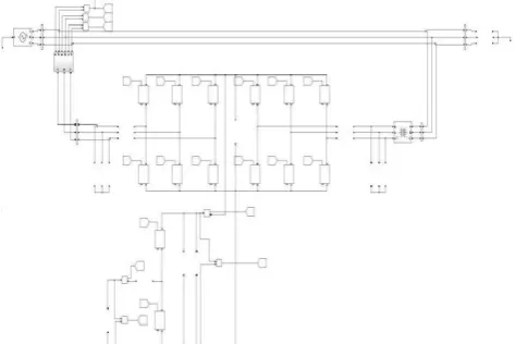
The one-line diagram of the system is shown in Fig. 1. The power stage consists of two back-to-back three-phase voltage source inverters connected through a dc-link capacitor. UCAP energy storage is connected to the dc-link capacitor through a bidirectional dc–dc converter. The series inverter is responsible for compensating the voltage sags and swells; and the shunt inverter is responsible for active/reactive power support and renewable intermittency smoothing. The complete circuit diagram of the series DVR, shunt APF, and the bidirectional DC– dc converter is shown in Fig. 2. Both the inverter systems consist of IGBT module, its gate-driver, LC filter, and an isolation transformer. The dc-link voltage Vdc is regulated at
260 V for optimum voltage and current compensation of the converter and the line–line voltage Vab is 208 V. The goal of this project is to
provide the integrated power conditioner and UCAP system with active power capability
1) To compensate temporary voltage sag (0.1–0.9 p.u.) and swell (1.1–1.2 p.u.), which last from 3 s to 1 min.
Figure 2. One-line diagram of power conditioner with UCAP energy storage
Figure 3. Model of power conditioner with UCAP energy storage
III.
RESULTS AND DISCUSSION
The simulation of the proposed UCAP-integrated IVDFC system is carried out in MATLAB for a 208 V, 60-Hz system where208 V is 1 p.u. The system response for a three-phase voltage sag, which lasts for 0.1 s and has a depth of 0.84 p.u., is shown. It can be observed from that during voltage sag, the source voltage Vs rms is reduced to 0.16 p.u. while the load voltage VL rms is maintained constant at around0.9 p.u. due to voltages injected in-phase by the series inverter. This can also be observed from the plots of the line–line source voltage, the line– line load voltages and the line–neutral injected voltages of the series inverter [Vinj2a, Vinj2b,
Vinj2c]. Finally, it can be observed from that Vinj2alags Vsab by 30◦, which indicates that it is in-phase with the line–neutral source voltage Vsa. In , plots of the bidirectional dc–dc converter are presented and it can be observed that the dc-link voltage Vfdc is regulated at 260 V, the average dc-link current Idclnkav and the average UCAP current I UCAP increase to provide the active power required by the load during the sag. Although the UCAP is discharging, the change in the UCAP voltage Ecap is not visible in this case due to the short duration of the simulation, which is due to limitations in MATLAB software. It can also be observed from the various active power plots shown where the power supplied to the load Pload remains constant even during the voltage sag when the grid power Pgrid is decreasing. The active power elicit of the grid is met by the inverter power Pinsssv, which is almost equal to the input power to the inverter Pdc_n available from the UCAP. Therefore, it can be concluded from the plots that the active power deficit between the grid and the load during the voltage sag event is being met by the integrated UCAP-DVR system through the bidirectional dc–dc converter and the inverter.
Figure 6. MATLAB Simulation of Proposed System
IV.
CONCLUSION
In this paper, the concept of integrating UCAP-based rechargeable energy storage to a power conditioner system to improve the power quality of the distribution grid is presented. With this integration, the DVR portion of the power conditioner will be able to independently compensate voltage sags and swells and the APF portion of the power conditioner will be able to provide active/reactive power support and renewable intermittency smoothing to the distribution grid. UCAP integration through a bidirectional dc–dc converter at the dc-link of the power conditioner is proposed. Designs of major components in the power stage of the bidirectional dc–dc converter are discussed. Average current mode control is used to regulate the output voltage of the dc–dc converter due to its inherently stable characteristic. A higher level integrated controller that takes decisions based on the system parameters provides inputs to the inverters and dc–dc converter controllers to carry out their control actions. The simulation of the UCAP-PC system is carried out using MATLAB. Hardware experimental setup of the integrated system is presented and the ability to provide temporary voltage sag compensation and active/reactive power
support and renewable intermittency smoothing to the distribution grid is tested Similar UCAP based energy storages can be deployed in the future in a micro grid or a low-voltage distribution grid to respond to dynamic changes in the voltage profiles and power profiles on the distribution grid.
V.
REFERENCES
[1]. S.A.Quresti and N.Aslam, "efficient power factor improvement technique and energy conservation of power system"int. conf. energy manage. Power del.., Vol.2, pp. 749- 752, NOV. 21-23, 1995.
[2]. J.J. Grainger and S.H.Lee, "optimum size and location of shunt capacitor for reduction of losses on distribution feeder", "IEEE trans power APP, sys.., vol. PAS100, no.3,pp.1105-1118, Mar.1981
[3]. R. Lasseter, "Microgrids", in Proc. of IEEE Power Engg. Soc. Winter meeting, New York, USA vol. 1, pp. 305-308, Jan. 2002.
[4]. J. G. Nielsen, M. Newman, H. Nielsen, and F. Blaabjerg, "Control and testing of a dynamic voltage restorer (DVR) at medium voltage level," IEEE Trans. Power Electron., vol. 19, no. 3, pp. 806–813, May 2004.
[5]. V. Soares, P. Verdelho, and G. D. Marques, "An instantaneous active and reactive current component method for active filters," IEEE Trans. Power Electron., vol. 15, no. 4, pp. 660–669, Jul. 2000.
[6]. K. Sahay and B. Dwivedi, "Supercapacitors energy storage system for power quality improvement: An overview," J. Energy Sources, vol. 10, no. 10, pp. 1–8, 2009.
[8]. W. Li, G. Joos, and J. Belanger, "Real-time simulation of a wind turbine generator coupled with a battery supercapacitor energy storage system," IEEE Trans. Ind. Electron., vol. 57, no. 4, pp. 1137–1145, Apr. 2010. [9]. H. Bevrani and T. Hiyama, "Frequency
regulation in isolated systems with dispersed power sources" , Chapter 12 in Intelligent automatic generation control, pp. 263‐277, CRC Press, NY, 2011.