© 2017 IJSRST | Volume 3 | Issue 6 | Print ISSN: 2395-6011 | Online ISSN: 2395-602X Themed Section: Science and Technology
Comparative study of a G+10 storied building using ETABS
and STAAD
Ram
anand Shukla
*1, Prithwish Saha
2*1Student, Civil Engineering Department, Heritage Institute of Technology, Kolkata, West Bengal, India 2Assistant Professor, Civil Engineering Department, Heritage Institute of Technology, Kolkata, West Bengal, India
ABSTRACT
Reinforced Concrete building structures are stretching their arms in the vertical direction with the growing demand of urban population. Plan dimensions have limited scope of expansion; hence it is obvious that the high-rise structures are getting popular among the designers round the word. This selection is also getting reinforced due to the invention of high strength materials, improved workmanship, excellent superior real-time model analysis data and several high efficient finite element analytical and design software packages, such as Staad Pro, ETABS, and SAP2000 etc. STAAD and ETABS both of the software are well equipped and very much capable of handling different shape of the structures, static and dynamic loadings and different material properties. In the present paper analysis of a G+10 storied building having a very simple plan dimension in both STAAD Pro and ETABS is carried out. The present study is mainly limited to the basic comparison between their analytical results under vertical loadings. The study then further extended and horizontal load is applied and the plan position of lift wall (shear wall) is optimized in terms of developed horizontal base shear at different support positions. Among different plan positions, it was found that the model with a centrally placed shear wall is most efficient in terms of handling the base shear.
Keywords: Staad Vs Etabs, Residential building in Etabs, Lateral Load, Shear/ Lift wall, Efficiency of Shear/Lift wall, Optimum position of Shear wall, Base shear, Centrally placed shear wall.
I.
INTRODUCTION
In modern world everything is perfectly engineered and developed to obtain its maximum utilization with minimum investment of 3M’s i.e. Mind, Money and Manpower. Every process whether it be manufacturing, processing, transporting or production is becoming more optimized and efficient with the help of new technologies. Construction and Engineering are among those sectors which are directly connected to the economy and safety of humans as a result of which their optimization in the amount of investment along with assured safety is becoming a necessity.
The available land area being limited, the investment for any construction project is increasing this gives rise to the wide spread construction of multi-storied High-Rise Superstructures both for residential and commercial use. Reinforced cement concrete structures have become widely accepted and implemented because of its various
advantages over other materials like Steel, Wood etc. Properly designed and engineered RCC structures can provide sufficient ductility to structures along with strength and they are easier to cast at greater altitudes than steel structures. These superstructures require large investments and thus to minimize the amount of capital along with conforming to the required minimum safety standards, various software like STAAD Pro and ETABS are developed.
results. Almost negligible manual calculations were required as both the software have all latest Indian and other codes incorporated in them which results in optimization in terms of material requirement maintaining the required standards of safety.
In this Paper a typical G+10 residential building was analyzed using both STAAD and ETABS. The objective of the analysis was to model a structure and apply vertical and horizontal loadings as per Indian Codes (IS-456, Is-875 {part 1, 2, 3}) to obtain the reactions and forces obtained from both the software and comparison of the results. The paper was also extended to the study of the reaction and base shear generated at the base of Shear wall due to horizontal loading and the most efficient position of the shear wall in the plan of the building was identified.
II.
PROBLEM DETAILS
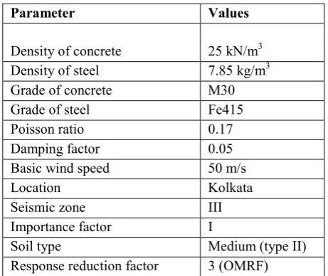
In the present study a RCC framed structure having an elevation of 34.5 m. Plan dimensions of the building is 25m × 25m. The location of the building is selected at Kolkata, India. Basic design parameters for the building are given below in a tabular form.
Table I. Basic data for analysis.
Parameter Values
Density of concrete 25 kN/m3
Density of steel 7.85 kg/m3
Grade of concrete M30 Grade of steel Fe415 Poisson ratio 0.17 Damping factor 0.05 Basic wind speed 50 m/s Location Kolkata Seismic zone III Importance factor I
Soil type Medium (type II) Response reduction factor 3 (OMRF)
Dimensional details and different source of masses are also tabulated below.
TABLE III. Dimensional details
Parameter Values
Plan dimension 25m × 25m Elevation from depth of fixity 34.5 m Floor/floor height 3m Total number of story G+10
Size of columns
0.85m × 0.85m (upto 5th floor)
0.65m × 0.65m (rest of the floors) Size of beams 0.4m × 0.4m Depth of slab 120 mm Thickness of shear wall 250mm
Following loads are considered on the structures.
Table III. Load details.
Parameter Values
Dead load
(Self-weight of slab, beam and column is taken care of by the software itself as they are modelled within the structure.)
12kN/m, 6kN/m (as wall load)
1.5 kN/m2 (Floor finish
including plaster)
Live load As per IS 875-Part 2-1987 for residential buildings
Wind load As per IS 875-Part 3-1987 for location Kolkata. Only static analysis is carried out. Seismic load Static as well as dynamic
analysis (response spectrum) is carried out following guidelines from IS 1893-2002.
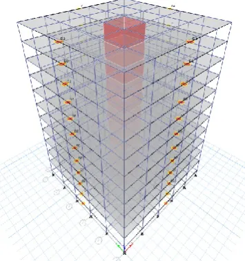
Figure 1: Rendered image from STAAD
Figure 2: Rendered image from ETABS
All the supports to the columns are made fixed at the base and those under the shear wall are pinned. The reason behind pinned support is to reduce the effect of developed moment at the base, which unnecessarily increases the thickness of the shear wall.
III. RESULTS
The structures are analyzed in both the softwares and the results are presented below. For all the graphs shown below, along X axis is node numbers and along Y axis is the support reactions in kN.
Figure 3: Comparison of reaction under dead load between STAAD and ETABS (without shear wall).
Figure 4: Comparison of reaction under live load between STAAD and ETABS (without shear wall).
Figure 5: Comparison of reactions under wind load along X direction between STAAD and ETABS
Figure 6: Comparison of reactions under dead load between STAAD and ETABS (with shear wall).
Figure 7: Comparison of reactions under live load between STAAD and ETABS (with shear wall).
Figure 8: Comparison of reactions under wind load along X direction between STAAD and ETABS (with
shear wall).
In the following figures, the deflected pattern of the two models under same horizontal wind load is presented.
Figure 9: Deflection pattern of the two models (left one is for Staad and right one is for ETABS) under wind
load.
Figure 10: Developed stresses at the 7th floor level in
slabs obtained from STAAD (left) and ETABS (right).
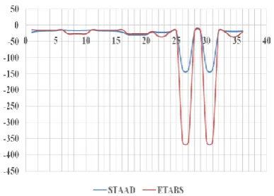
Figure 11: Variation of developed horizontal support reactions under wind load for different positions of the
lift wall (shear wall).
IV. INTERPRETATION OF RESULTS
The results obtained are presented in a graphical form for better comparison between the software. Following are the observations
different nodes. Results from both the software are in close liaison. It also signifies that the model is geometrically fit for analysis.
2) Figure 5 represents the developed horizontal reaction forces under wind load. Here it is found that the support reactions are greatly varied. Now, is case of ETABS, it is showing higher values. The reason behind this typical outcome is due to the presence of diaphragm in ETABS model. Wind load is applied directly on the model in case of STAAD, but in case of ETABS, it is applied using a diaphragm. Hence the load is managed in a better way.
3) The same variations are studied for models with lift well or shear wall. Figure 6 and 7 shows the variation of dead load and live load at nodes with the centrally placed shear wall. Both the results show that except the nodal positions near to the shear wall, all the other values are similar. Only the shear wall is redistributing the horizontal load.
4) Figure 9 shows the deflected shape of the building under wind load, which shows same pattern for both the cases.
5) Figure 10 represents the stress diagram of slabs at 7th
story level under dead load. These floor slabs were not meshed during modeling. From the fig it can clearly visible that ETABS has meshed the plate automatically and found out the stresses more accurately. But STAAD only calculated the stress at the given plate dimension, without meshing the plates. So when it comes to analysis of plates, ETABS is to some extent superior, compared to STAAD.
6) Finally figure 11 shows the variation of developed base shear due to wind load for different positions of lift well. Five numbers of variations are considered. They are without core (shear wall), centrally placed core, two cores along the application of horizontal load (2 cores X), two cores across the direction of application of wind load (2 cores Z) and finally two cores placed diagonally opposite positions (2 cores dig). From the graph, it is clear that all the positions of shear wall are carrying the horizontal load in nearly similar fashion. Only in case of centrally placed core, there are four points with much higher values and the rest of the values are quite less compared to other positions. The significance of this result is that those four points are the support points under the shear wall, which is actually absorbing the
maximum amount of horizontal load and transmitting it to the ground. This factor results in lesser amount of developed base shear in other column supports. This is highly beneficial in terms of design criteria, because lesser amount of horizontal reaction will lead to lesser amount of developed bending moment in columns. Lesser moment will finally lead to lesser amount of consumption of reinforcement, which ultimately will make the whole structure economical. So it can be concluded that when a lift is required to be placed in a building, a try should always be made to place it as much centrally as possible for a better design of the whole structure.
V.
REFERENCES
Authors of this paper have studied some of the literatures ([1]-[4]) available over the internet to have some idea about the types of comparison that can be made for analysis. These literatures were found helpful to the present authors.
[1]. Sabeer M and Peera D G., "Comparison design result of RCC building using STAAD and ETABS
software", International Journal of Innovative
Research in Advanced Engineering (IJIRAE), 2, 8, August 2015, pp. 92-97.
[2]. Adhikari S K and Rajasekhar K., "Comparative static and Dynamic study on seismic analysis of uniform and non uniform column sections in a
building.", International Journal of Innovative
research in Science, Engineering and Technology,
4,8, August 2015, pp. 6830-3837.
[3]. Guleria A., International Journal of Engineering
Research & Technology (IJERT, )3, 5, May 2014,
pp. 1481-1485.
[4]. Mahesh S and Rao B P., IOSR Journal of
Mechanical and Civil Engineering (IOSR-JMCE),