141
Experimental Analysis Of CFST Sections With
Tie And Self Curing Agent
Ramesh R, Balamurali K, Muthukeerthana S
Abstract— Present paper focuses on the construction and testing of concrete filled steel tubular section. Concrete in filled Steel tubular section has gained the advantage of composite member. Generally, composite members are constructed using two or more different materials to obtain different engineering properties. Use of steel as an external mould neglects the use of shuttering panels, increases the mechanical properties of the section and neglects the water bath of the section which is often done in curing period. Water bath in one of the important method of curing for vertical structural elements. To reduce such instant, this study investigates the role of PEG400 as a self-curing agent, the percentage of PEG400 by weight of cement is 2% as the dosage of internal curing. The test results were studied for three mixes that is for M20, M25 and M30 mixes. Concrete mixes prepared using internal curing compound PEG400 with specified target strength values calculated during design mix for M20, M25, and M30 grade of concretes. Index Terms— CFST Column, PEG400, Compressive Strength, Stiffeners, Reinforced concrete, Buckling, Workability.
————————————————————
1
I
NTRODUCTION Concrete and steel are the most common construction materials used from 1800’s to present. Both the steel and concrete are said to be heterogeneous material, manufacturing of steel and concrete utilizes different mineral ores [1]-[3]. Combination of steel and concrete are said to be composite sections, which increases the load carrying capacity and other mechanical properties of the sections. Steel concrete composite sections has the advantage of using both steel and concrete, steel has high yielding capacity and concrete has tough strain capacity, using the combination of both materials increases the advantage of improving the material property [5]-[9]. Currently, composite structural elements mainly used in high rise buildings, long span bridges and other types of special structures, use of composite steel concrete sections neglects the use of steel reinforcement thereby reducing the construction cost [10]. Generally, steel concrete composite sections are classified into two group first - concrete in filled steel encased section, second – concrete encased steel infill sections. Both the type of section have unique engineering properties [12]-[14]. In concrete in filled steel encased section, the steel tube act as an external mold in which concrete are poured inside the steel tube [16]-[17]. This system improves the efficiency and workability of the construction activities. Second, in concrete encased steel infill sections hollow steel pipes are placed at the concrete core, normally this type of sections are often used in industrial buildings, the central core of the steel pipe is used to carry the cable and other wiring units. CFST sections are made in different shapes as per the end user requirement, normally CFST sections are in the form of tubular shape and also it can be made in the form of square, rectangle, etc., [18] Use of CFST sections willincreases the deflection property of the section, highly deflecting material can be adopted in earthquake prone areas to prevent loss of life [20].
2
MATERIALS AND PROPERTIES
2.1 Cement
Cement is manufactured in a controlled environment, in which all the raw ingredients are burned to a temperature of
1200 – 1500oc and then dried at room temperature to form
clinkers and these clinkers are grounded with gypsum to enhance the setting time of the cement.
Table: 1 shows the properties of cement.
Particulars Permissible values Test values
Fineness modulus ≤10% 4.375%
Specific gravity 3.0-3.15 3.15 g/cc
Initial setting time 30min 32min
Final setting time 600min 580min
Specific gravity 3.0-3.15 3.15 g/cc
2.2 AGGREGATE 2.2.1FINEAGGREGATE
The M- sand having fineness modules of 3.18.The specific gravity of fine aggregate is 2.37. It is found that sand with the fineness modulus below 2.5 gives the concrete a sticky consistency. Making it is difficult to compact. Sand with a fineness of about 3.0 gives the best workability and compressive strength.
Fineness modulus = 3.17
2.2.2
COARSEAGGREGATEThe crushed stone materials which are retained on 4.75mm sieve are called coarse aggregate. Locally available coarse aggregate having the maximum size of 20mm sieve is used in the present work. According to IS 383:1970, maximum 20mm coarse aggregate is suitable for concrete work. Specific gravity
————————————————
Ramesh R is currently working as an Assistant Professor in Sri Krishna College of Technology, India, E-mail: [email protected]
Balamurali K is currently pursuing master’s degree program in Sri Krishna College of Technology, India, E-mail: [email protected]
of coarse aggregate G= 2.63
2.3POLY ETHYLENE GLYCOL
Polyethylene glycol, abbreviation (PEG400) is termed in combination with a numeric suffix which indicates the average molecular weights. One common feature of PEG400 appears to be the water-soluble nature. Polyethylene glycol is non-toxic, odourless, neutral, lubricating, non-volatile and non-irritating and is used in a variety of pharmaceuticals.
2.4 Steel Tube
Concrete filled steel tube column have many excellent structural properties, such as high compressive strength, large ductility. The thickness of steel tube is 2mm.Then, composite tubular column have been gradually used widely in the world. Fe 240 mild steel is used as per IS 2062.
3 T
IE BARSGenerally tie bars are called as stirrups in axially loaded structural elements, these are used to hold the main rod and distribution rods in position and transfers the shear stress which acts on the surface of the element. At present tie bars are provided in the form of horizontal bracings to distribute the load from the steel section to the concrete core. The HYSD bars are used and provided in the middle of the column with the thickness of 8mm.
4 M
IXD
ESIGNThe mix design of M20, M25 and M30 grade concrete given below is based on the guidelines given in Indian Standard IS 10262 : 2009.
Table: 2 shows the Mix Proportions of Different grades.
Mix Proportion Cement Fine aggregate
Coarse
aggregate Water
Trial – 1 M-20
grade 369 646 1108.14 203
Mix ratio 1 1 1.7 3 0.5
Trial – 2 M-25 grade 406 635.55 3 0.5
Mix ratio 2 1 1.5 2.68 0.5
Trial - 3 M-30 grade 451 621.3 1066.41 203
Mix ratio 3 1 1.37 2.36 0.5
5 EXPERIMENTAL INVESTIGATION
5.1CFSTSPECIMENS
The concrete filled steel tube consists of 114mm dia (ODI) and inner dia of 110 mm and 300mm height and a thickness of 2mm. Concrete was then filled in mould in three layers, while filling the mould concrete was compacted using tamping rod
of 600mm length having diameter of 110mmthen the mould is
kept on the plane surface in the laboratory for 24 hours and then kept for curing. For thus study 18 specimens were casted and tested to be carried out for 28 days.
5.1
CURING
OF
SPECIMENS
BY
PEG
Poly ethylene glycol (by adding 1% &1.5% of PEG-400 by weight of cement) which helps in self-curing with better hydration which reduces shrinkage cracks and hence increases the strength and is compared with that of conventional cured Concrete of the various grade. The casting of specimens are kept for curing in atmosphere.
6 RESULT
AND
DISCUSSION
6.1
LOAD
CALCULATION
FOR
NORMAL
CFST
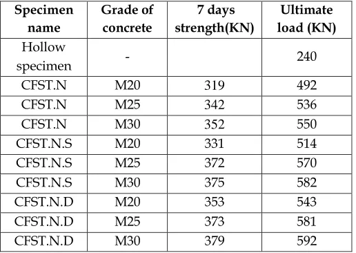
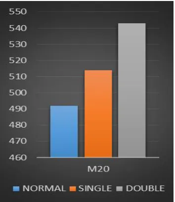
When compared with normal CFST of M20 grade, the CFST value of single and double tie bar are increased up to 4.47% and 10.3% respectively. When compared with normal CFST of M25 grade, the CFST value of single and double tie bar are increased up to 6.3% and 8.4% respectively. When compared with normal CFST of M30 grade, the CFST value of single and double tie bar are increased up to 5.8% and 7.6% respectively.
Table 3: Load calculation for normal CFST
Specimen name
Grade of concrete
7 days strength(KN)
Ultimate load (KN) Hollow
specimen - 240
CFST.N M20 319 492
CFST.N M25 342 536
CFST.N M30 352 550
CFST.N.S M20 331 514
CFST.N.S M25 372 570
CFST.N.S M30 375 582
CFST.N.D M20 353 543
CFST.N.D M25 373 581
CFST.N.D M30 379 592
6.2LOADCALCULATIONFORPEGCFSTCOLUMN
143
Table 4: Load calculation for PEG CFST
Specimen name
Grade of concrete
7 days strength(KN)
Ultimate load (KN)
CFST.P M20 254 403
CFST.P M25 283 450
CFST.P M30 315 490
CFST.P.S M20 269 426
CFST.P.S M25 308 486
CFST.P.S M30 341 530
CFST.P.D M20 288 449
CFST.P.D M25 337 511
CFST.P.D M30 355 542
6.3COMPARISONOFTESTRESULTS
Table 5: Comparison of test results
Specimen Ultimate load ( KN)
With curing Without curing
With curing
Without curing
CFST.N M2O CFT.P M20 492 403
CFST.N M25 CFT.P M25 536 450
CFST.N M30 CFT.P M30 550 490
CFST.N.S M20
CFT.P.S
M20 514 426
CFST.N.S M25
CFT.P.S
M25 570 486
CFST.N.S M30
CFT.P.S
M30 582 530
CFST.N.D M20
CFT.P.D
M20 543 449
CFST.N.D M25
CFT.P.D
M25 581 511
CFST.N.D M30
CFT.P.D
M30 592 542
The following graphs shows variation of strength for different grades of concrete cured at normal Temperature:
Fig 1: Comparison of normal curing column with load
380 390 400 410 420 430 440 450 460
M20
C
o
m
p
re
ssi
st
re
n
gth
in
M
p
a
NORMAL SINGLE TIE BAR DOUBLE TIE BAR
Fig 2: Comparison of PEG column with load
492
403 514
426 543
449
0 100 200 300 400 500 600
M20 M20
co
m
p
re
ssi
ve
st
re
n
gth
in
M
p
a
NORMAL SINGLE TIE BAR
DOUBLE TIE BAR
426
486 530
0 100 200 300 400 500 600
Com
p
ressi
ve
str
en
gth
in
M
p
a
single tie bar M20 single tie bar M25
single tie bar M30
Fig 4: Comparison of single tie bar curing column
449
511 542
0 100 200 300 400 500 600
M25
Co
m
p
re
ssi
ve
st
re
n
gth
in
M
p
a
double tie bar M20 double tie bar M25
double tie bar M30
Fig 5: Comparison of double tie bar curing column
0
319
492
0
331
514
0
353
543 y = 271.5x - 244.33
R² = 0.9708
0 200 400 600
0 DAYS 7 DAYS 28 DAYS
Co
m
p
re
ssi
ve
st
re
n
gth
in
Mpa
Curing period
NORMAL SINGLE TIE BAR
DOUBLE TIE BAR
Fig 6: PEG used M20 grade 7 days and 28 days strength comparison
0
254
403
0
269
426
0
288
449 y = 213x - 194.33
R² = 0.9775
0 200 400 600
0 DAYS 7 DAYS 28 DAYS
Co
m
p
re
ssi
ve
st
re
n
gth
in
Mpa
curing period
NORMAL SINGLE TIE BAR
DOUBLE TIE BAR
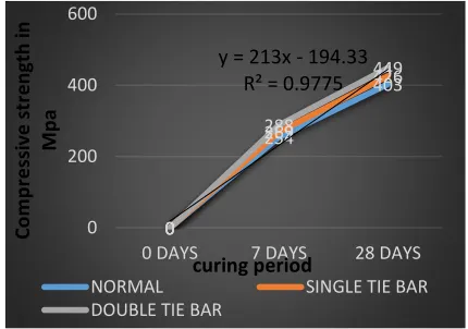
Fig 7: M20 grade 7 days and 28 days strength comparison
Fig 8: CFST SINGLE TIE COLUMN TOTAL DEFORMATION
Fig 9: CFST DOUBLE TIE COLUMN TOTAL DEFORMATION
7 CONCLUSION
145
member has increased up to 100 N/mm2, after 28 days of test.
Comparing the results of fig 6 and 7, usage of PEG 400 for M20 grade concrete in double tie bar specimen has gained the
strength of 543 N/mm2, whereas double tie bar specimen
without PEG 400 has decreased the strength up to 100
N/mm2. It is clearly shown that PEG400 can be adopted for
self-curing agent in concrete filled steel tubular sections and concrete encased steel tubular sections. The buckling behavior of CFST sections are studied in Ansys software and it is shown in fig 8 and 9.
A
CKNOWLEDGMENTThe authors wish to thank Sri Krishna College of Technology for providing materials for the project.
R
EFERENCES[1] S. Jegadesh and S. Jayalekshmi. “Load-bearing capacity of
axially loaded circular concrete-filled steel tubular columns,” Proceedings of the Institution of Civil Engineers: Structures and Buildings, vol. 169, no. 7, pp. 508–523, 2016.
[2] N.E. Shanmugam, and B. Lakshmi. “State of the art report
on steel–concrete composite columns,” Journal of Constructional Research, vol. 57, no. 10, pp. 1041–1080, 2001.
[3] S. De Nardin. “Theoretical-experimental study high
strength concrete-filled steel tubes,” M.S. thesis,
EESC-USP, Sao Carlos-SP, in Portuguese, 1999.
[4] K. Cederwall, K. Engstrom and M. Grauers.
“High-strength concrete used in composite columns,”
in Proceedings of High-Strength Concrete–2nd
International Symposium, pp. 195–214, Detroit, MI, USA, 1990.
[5] L. Han, W. Li and R. Bjorhovde. “Developments and
advanced applications of concrete-filled steel tubular (CFST) structures: members,” Journal of Constructional Steel Research, vol. 100, pp. 211–228, 2014.
[6] L. Han, H. Shan-Hu and F. Liao. “Performance and
calculations of concrete filled steel tubes (CFST) under axial tension,” Journal of Constructional Steel Research, vol. 67, no. 11, pp. 1699–1709, 2011.
[7] M. A. Bradford. “Design strength of slender concrete filled
rectangular steel tubes,” ACI Structural Journal, vol. 93, no. 2, pp. 229–235, 1996.
[8] M. D. O'Shea and R. Q. Bridge. “Design of thin-walled
concrete filled steel tubes,” Journal of Structural Engineering, vol. 126, no. 11, pp. 1295–1303, 2000.
[9] B. Uy. “Local and postlocal buckling of fabricated steel
and composite cross sections,” Journal of Structural Engineering, vol. 127, no. 6, pp. 666–677, 2001.
[10]K. K. Choi and Y. Xiao. “Analytical studies of
concrete-filled circular steel tubes under axial
compression,” Journal of Structural Engineering, vol. 136, no. 5, pp. 565–573, 2010.
[11]Z. Z. Ou, B. Chen, K. H. Hsieh, M.W. Halling and P.J.
Barr. “Experimental and analytical investigation of concrete filled steel tubular columns,” Journal of Structural Engineering, vol. 137, no. 6, pp. 635–645, 2011.
[12] T. Perea, R. T. Leon, J. F. Hajjar, and M. D. Denavit.
“Full-scale tests of slender concrete-filled tubes: axial
behavior,” Journal of Structural Engineering, vol. 139, no. 7, pp. 1249–1262, 2013.
[13]L. H. Han. “Flexural behavior of concrete-filled steel
tubes,” Journal of Constructional Steel Research, vol. 60, no. 2, pp. 313–337, 2004.
[14]L. H. Han. “Further study on the flexural behavior of
concrete-filled steel tubes,” Journal of Constructional Steel Research, vol. 62, no. 6, pp. 554–565, 2006.
[15]H. Lu, L. H. Han and X. L. Zhao. “Analytical behavior of
circular concrete-filled thin-walled steel tubes subjected to bending,” Thin-Walled Structures, vol. 47, no. 3, pp. 346– 358, 2009.
[16] C. W. Roeder, D. E. Lehman and E. Bishop. “Strength and
stiffness of circular concrete-filled tubes,” Journal of Structural Engineering, vol. 136, no. 12, pp. 1545–1553, 2010.
[17] J. Moon, C. W. Roeder, D. E. Lehman and H. Lee.
“Analytical modeling of bending of circular concrete-filled steel tubes,” Engineering Structures, vol. 42, pp. 349– 361, 2012.
[18] L. H. Han, G. H. Yao and Z. Tao. “Performance of
concrete-filled thin-walled steel tubes under pure torsion,” Thin-Walled Structures, vol. 45, no. 1, pp. 24–36, 2007.
[19] J. Nie, Y. Wang and J. Fan. “Experimental study on
seismic behavior of concrete filled steel tube columns under pure torsion and compression–torsion cyclic load,” Journal of Constructional Steel Research, vol. 79, no. 12, pp. 115–126, 2013.
[20]Y. Wang, J. Nie and J. Fan. “Theoretical model and
investigation of concrete filled steel tube columns under
axial force–torsion combined action,” Thin-Walled