ISSN (e): 2250-3021, ISSN (p): 2278-8719
Vol. 08, Issue 5 (May. 2018), ||VII|| PP 01-07
International organization of Scientific Research
1 | P a g e
Application of Hyper-Fuzzy Logic Type -2 in Field Oriented
Control of Induction Motor with Broken Bars
Belhamdi Saad
1*, Chekroun Salim
1, Djalal Eddine Khodja
11 Electrical Engineering Laboratory, University of Mohamed Boudiaf- M'sila, Algeria
Corresponding author:Belhamdi Saad
Abstract
:
The aim for this paper is a proportional and integral (PI) controller and fuzzy logic type-2 (FLCT2) controller devoted to improve the performance of Indirect field orient control (IFOC) strategy of induction motor with broken bars. In addition, the paper describes a model of induction motor in d-q reference frame theory and its computer simulation in MATLAB/SIMULINK®, fed by Pulse Width Modulation (PWM) inverter to be studied. The performance of the Indirect Field orientated control with a PI and FLCT2 is tested under different speed command and load disturbances. And also show a better robustness beside the parametric variations of the motor. Type 2 fuzzy logic systems have recently been utilized in many control processes due to their ability to model uncertainty, so we are concerned with the use of a new fuzzy logic type-2 controller to improve the performance of conventional PI controller.Key words: induction motor, fuzzy logic type-2, Indirect field orient control, Robustness, Rotor fault.
--- --- Date of Submission: 25-04-2018 Date of acceptance: 14-05-2018 --- ---
I.
INTRODUCTION
The induction motor (IM) has great variety of applications in industrial process when is used as fans or pumps, heating and air conditioning. Its design simplicity, reliability, absence of collector is the main reasons for its success. But its mathematical model is complex, multi-variable or linear, with a strong coupling between the variables, input, and output and internal, which has long delayed the onset of effective; appropriate controls this type of engine [1]. Although the induction motor is well constructed and robust, the possibility of faults is inherent due to stresses involved in the conversion of electrical to mechanical energy and vice verse. For productivity and safety reason, there has been an increasing demand for automated preventive maintenance and fault diagnostic system.
In the recent years, the reliability of the electric machine drives, particularly in some critical applications has become a very interesting research topic. In the literature, many researches have been presented on the fault-tolerant control strategies of electric machine drives [12-13]. In [12-14], some methods to control a 3-phase IM under speed-sensor fault, in [10-14], different methods to control a 3-phase motor under open-circuit fault and in [10-13], some techniques to control an IM under inverter faults have been proposed.
In this manner, over the past 30 years, several artificial intelligence techniques have been developed and applied in the monitoring processes of faults, among them, the Artificial Neural Networks (ANNs), Fuzzy Logic (FL) [2-3]. The most commonly used controller for the speed control of Induction motor is Proportional plus Integral (PI) controller However, the PI controller has some demerits such as: the high starting overshoot, sensitivity to controller gains and sluggish response due to sudden disturbance. To overcome these problems, replacement of PI controller by an intelligent controller based on Fuzzy set theory is proposed in this work.
II.
FIELD ORIENTED CONTROL
The field oriented control introduced for the first time at the hands of Blashka in 1971 as an alternative to bring the induction motor instead of the DC motor in industrial applications that required high dynamic performance [5]. In FOC, the space phasor of the stator current is decoupled into two components torque current component and flux current component. To implement that, the position and magnitude of the rotor flux are required and this can be done directly by using sensor to measure the rotor flux or indirectly by estimating the rotor flux. In this paper the rotor flux is estimated by indirect method [6-8]. This means that, the d-axis rotor flux is equal to the rotor flux and the q-axis rotor flux becomes zero so the rotor flux can be calculated as[7-15].
r ds r r qs r r M Φ I 1 T M ω I T Φ s
The electromagnetic torque is found as:
e ds qs qs ds
3
C p. Φ .I Φ .I 2
The equations tension of the machine is written to the system related to the rotating field configuration as follows: dr Φ r ω dt qr dΦ qr .I r R 0 qr Φ r ω dt dr dΦ dr .I r R 0 ds Φ s ω dt qs dΦ qs .I s R qs V qs Φ s ω dt ds dΦ ds .I s R ds V
The main objective of the vector control of induction motors is, as in DC machines, to independently control the torque and the flux; this is done by using a d-q rotating reference frame synchronously with the rotor flux space vector . In ideally field-oriented control, the rotor flux linkage axis is forced to align with the d-axes, and it follows that [6].
0 qr Φ constant r Φ dr Φ
Applying the result of (4) and (5), namely field-oriented control, the torque equation becomes analogous to the DC machine and can be described as follows:
e r qs
rc
3
M
C
p.
Φ I
2
L
Consequently, the dynamic equations (3) yield:
ds s sc ds s sc qs
qs s sc qs s r s sc ds
rc
V R .σ L I ω .σ L .I M
V R .σ L I ω Φ ω σ.L .I L s s
III.
MODELING AND DESIGN OF FLCT2 SYSTEM
The structure of a type-2 FLS is shown in figure 1. It is similar to its type-1 counterpart, the major difference being that at least one of the fuzzy sets in the rule base is type-2. Hence, the output of the inference engine is type- 2 sets and a type-reducer is needed to convert them into type-1 sets before defuzzification can be carried out.
A. Inference
An interval type-2 FLS is employed [10-11]. “Interval” means that the input/output domains are characterized by interval type-2 sets [3-8].
International organization of Scientific Research
3 | P a g e
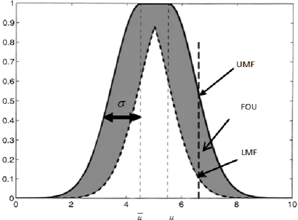
Figure 1. Structure of a type-2 FLS.Of all elements in the FOU (secondary membership grades) area nifty. The inference engine then matches the fuzzy rules in the rule base. To compute unions and intersections of type-2 sets, compositions of type-2 relations are needed. Just as the sup-star composition is the backbone computation for a type-1 FLC, the extended sup-star composition is the backbone for a type-2 FLC [4-9].
Figure 2. Membership Function Interval Type-2 Fuzzy Logic Set.
B. Type-Reduction and Defuzzification
C. Rules
linguistic variable exists. This output variable is the α (α
[-10; 10]). Each linguistic variable possesses seven linguistic values: NB, NM,NS, ZE, PS, PM,PB [7].The proposed controller uses following linguistic labels NB (negative big), NM (negative medium), NS (negative small), ZE (zero), PS (positive small), PM (positive medium), PB (positive big). Each of the inputs and output contain membership function with all these seven linguistics.
Table 1 shows one of possible control rules based on seven membership functions [15]. Table 1 : The fuzzy control rule bases
e
∆e NB NM NS ZE PS PM PB
NB NB NB NB NB NM NS ZE
NM NB NB NB NM NS ZE PS
NS NB NB NM NS ZE PS PM
ZE NB NM NS ZE PS PM PB
PS NM NS ZE PS PM PB PB
PM NS ZE PS PM PB PB PB
PB ZE PS PM PB PB PB PB
For indirect field orientation (Fig.3), the control variables are Ids* and Iqs* which represent respectively the desired rotor flux component and torque Component. These components can be generated from a flux control loop (for Iqs*), and from a speed control loop (for Ids*).
Figure.3: Indirect Vector Controlled induction motor block diagram with the Fuzzy Logic Controller type-2 [6]
IV.
RESULT AND DISCUSSION
The simulation results for FOC and FLT2 are discussed here, the case of study is for induction motor which has the data in Appendix. In order to analyze the drive system performance for speed and torque responses, with Healthy case, the above-presented system has been simulated using MATLAB/SIMULINK software. A squirrel cage induction motor with a rated power of 1.1 kW has been used. In this section, simulation results are presented to show the performance of the proposed Fuzzy Controller, meanwhile, the proposed control method has been compared with the PI control method.
The reference speed is 120 rad/sec. it is observed that motor pick up the reference speed at t = 0.4 sec figure.4 shows the performance characteristic of motor. This is due to the facts that the fuzzy control is a
International organization of Scientific Research
5 | P a g e
nonlinear control and the IM motor mathematical model is also non-linear and complex. The FLCT2 controller performed better performance with respect to rise time and steady state error, we perform a simulation of a first broken rotor bar at t = 2s increasing resistance 11fois the resistance of the bar, the second adjacent broken rotor bar at t = 3 s. In bars break during we note that the speed remains constant insensitive broken the bars, demonstrating the robustness of the order by fuzzy logic type-2. There is a small fracture strain of the bar. In fact, it is on (Figure 4b) which cancels the loads instructions FLCT2 effects perturbations applied at time t = 0.8s, so also we see in this figure that the electromagnetic torque following these instructions without causing overflows considered moments and with less vibration. We also note the increase in the amplitude modulation of the stator current during the second broken rotor bar. The control input (u) has chattering in IFOC, but is free of chattering in FLCT-2. The field orientation is obvious, as the d-axis stator current and rotor flux remain constant. The speed response is shown in Figure.5.a. It can be seen clearly that the FLCT-2 provides a minimum response time and robust speed response compared to the traditional PI controller.Figure.4:Simulated results of the comparison between the PI and FLCT-2 of Induction Motor
V.
COMPARISON BETWEEN IFOC AND FLCT-2
For a comparative analysis of IFOC and FLCT-2, the performance of both methods in transients and steady-state operation must be studied; there are usually performance criteria such as: Square Error (ISE), the Integrated Absolute Error (IAE) and integral time-weighted absolute error (ITAE). That can be evaluated logically in frequency domain. These performance criteria are including the overshoot, rise time, settling time and steady-state error. In addition, it has been indicated the robust of the drive system.
In this study are utilized to judge the performance of the controllers. ISE, IAE and ITAE criterion is widely adopted to evaluate the dynamic performance of the control system.
The index ISE, IAE and ITAE is articulated as follows [18]:
tdt e ISET
0 2
(7)
dt t e IAE
T
0
)
dt t e t ITAE
T
0
)
( (9) ISE: integral squared error, IAE: integral absolute error,
ITAE: integral time-weighted absolute error.
For quantitative comparison between two methods, ISE, IAE and ITAE are used as the criterion. Table.2 shows the ISE, IAE and ITAE values of the simulation results of Indirect Field oriented control and Indirect Field oriented control using the FLCT-2 controller (FLCT-2, IFOC). Actually these performances index are obtained at the end of the simulation time (t=4 sec) with a sampling period h=1*e-5.
Table 2.Quantitative comparison between the FLCT-2 and IFOC Controllers
Index
IFOC
FLCT-2 IFOC PI
ISE Speed 3.009 10.01
Flux rotor 1.464 2.563
IAE Speed 2.668 3.948
Flux rotor 2.419 3.2
ITAE Speed 4.444 6.59
Flux rotor 4.485 6.401
VI.
CONCLUSION
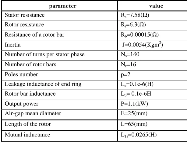
In this paper, we proposed a hybrid control of an induction motor with broken bars. This command combines the advantages of two techniques considered robust and which are the control by PI and the fuzzy control type-2. This structure aims to exploit the robustness and the speed of the fuzzy logic type-2 during the transient regime and the flexibility of the fuzzy controller during the steady state. The simulation results show that the hybrid control by PI and fuzzy logic gives better results compared to the other commands studied previously. The criterions for a fair comparison between FLCT-2 and IFOC have been established and the results of simulation tests have been presented to show the performance of both methods in various conditions and new comparison between the two methods (FLCT-2) and (IFOC) under the influence of new factors (ISE, IAE, ITAE) that have not been used before judging one of these two methods in terms Performance and control. Appendix
The parameters of the machine used for simulation are listed below [7]:
parameter value
Stator resistance Rs=7.58(Ω) Rotor resistance Rr=6.3(Ω) Resistance of a rotor bar Rb=0.00015(Ω)
Inertia J=0.0054(Kgm2)
Number of turns per stator phase Ns=160 Number of rotor bars Nr=16 Poles number p=2 Leakage inductance of end ring Le=0.1e-6(H)
Rotor bar inductance Lb= 0.1e-6H
Output power P=1.1(kW)
Air-gap mean diameter E=25(mm)
Length of the rotor L=65(mm)
Mutual inductance L1s=0.0265(H)
REFERENCES
[1]. Q. Liang and J. M. Mendel, "Interval type-2 fuzzy logic systems: Theory and design", IEEE Trans. Fuzzy Syst; 2000, 8(5), 535–550.
International organization of Scientific Research
7 | P a g e
[3]. J. M. Mendel and R. I. B. John. "Type-2 fuzzy sets made simple", IEEE Transactions on Fuzz Systems,2002; 10(2), 117–127.
[4]. I. Takahashi and T. Noguchi," A New Quick Response and High-Efficiency Control Strategy of an Induction Motor", IEEE Trans. On IA, 1986; 22(5), 820-827.
[5]. H. Hagras. Type-2 FLCs, "A new generation of fuzzy controllers", IEEE Computational Intelligence Magazine, 2007; 2, 30-43.
[6]. Vinod Kumar, R. R. Joshi," Hybrid Controller based Intelligent Speed Control of Induction Motor", Journal of Theoretical and Applied Information Technology, 2006; 3 (1), 71- 75.
[7]. Belhamdi, S, Goléa, A" Direct Torque Control for Induction Motor with broken bars Using Fuzzy Logic Type-2" Association for the advancement of modeling & Simulation techniques in Enterprises , advancement of modeling C ,2015;70(2),15-28.
[8]. Belhamdi, S, Goléa, A," Fuzzy logic Control of Asynchronous Machine Presenting Defective Rotor Bars", Association for the advancement of modeling & Simulation techniques in Enterprises, advancement of modelling C, 2013;68(2), 54-63.
[9]. Castillo, O, P. Melin," A review on the design and optimization of interval type-2 fuzzy controllers" Applied Soft Computing, 2012; 12, 1267–1278.
[10]. J.M.Mendel,R.I.John,andF.Liu, "Interval type-2fuzzy logic systems made simple" ,IEEE Transactions on Fuzzy Systems,2006; 14(6), 808–821.
[11]. Ashok Kusagur, F.Kodad, BV, Sankar Ram," Al based design of a fuzzy logic scheme for speed control of induction motors using SVPWM technique",Proc, Int .Jr .Comp. Sci & Network Security, 2009;9(1), 74-80.
[12]. S. Fan and J. Zou, "Sensor Fault detection and fault tolerant control of induction motor drivers for electric vehicles," in 7th International Power Electronics and Motion Control Conference (IPEMC),2013; 1306–1309.
[13]. G. Grandi, et al., "Fault-tolerant control strategies for quad inverter induction motor drives with one failed inverter," in 2012 XXth International Conference on Electrical Machines (ICEM), 2012; 959–966. [14]. X. Zhang, et al., "Sensor fault detection, isolation and system reconfiguration based on extended Kalman
filter for induction motor drives," IET, Electric Power Applications,2013;7(7), 607–617.
[15]. M. Jannati, et al., "Speed Sensorless Vector Control of Unbalanced Three-Phase Induction Motor with Adaptive Sliding Mode Control," IJPEDS, 2014; 4(3), 406–418.
[16]. A. S. Ahmed, et al., "Fault-tolerant technique for Δ-connected AC-motor drives," IEEE Transactions on Energy Conversion, 2011;26(2), 646–653.
[17]. F. Meinguet, et al., "A method for fault detection and isolation based on the processing of multiple diagnostic indices: application to inverter faults in AC drives," IEEE Transactions on Vehicular Technology, 2013; 62(3), 995–1009.
[18]. A. Aissaoui, M. Abid, H. Abid, A. Tahour, A. Zeblah,"A Fuzzy Logic Controller for Synchronous Machine", Journal of Electrical Engineering, 2007, Vol. 58, No. 5, pp.285-290.
![Figure.3: Indirect Vector Controlled induction motor block diagram with the Fuzzy Logic Controller type-2 [6]](https://thumb-us.123doks.com/thumbv2/123dok_us/7813025.1663281/4.595.82.522.408.633/figure-indirect-vector-controlled-induction-diagram-fuzzy-controller.webp)