Page 422 www.ijiras.com | Email: [email protected]
Analysis And Design Of Multistoried RCC Building (G+2)
Compared With STAAD Pro
S. Gayathri
G. Raghu
V. Rajeswari
UG Student, DMSSVH College, Machilipatnam, Andhra Pradesh, India
K. Nehemiya
Assistant Professor in Civil Engineering Department, DMSSVH College, Machilipatnam,
Andhra Pradesh, India
I. INTRODUCTION
Structural design is an art of designing, with economy and elegance, a safe serviceable and durable structure. Slabs are the main structural components, which directly exposed to the live loads in a structure, whether it is multi storied structure or a load bearing structure. In case of multistoried structure the loads from the slabs is transferred to the beams and in turn to the columns, which are resisting on a footing. The footing transfers the load to the soil there by the load is safely transferred to the earth. Where as in case of load bearing structures the loads from the slabs is directly transferred to the load bearing walls, which in turn transferred to the earth through isolated footings. This present project is the design of such multistoried structure which is practically viable
Here in this paper, work based on software named “STAAD. Pro” has been used. Few standard problems also have been solved to show how “STAAD. Pro” can be used in different cases. These typical problems have been solved using basic concept of loading, analysis, condition as per IS code.
These basic techniques may be found useful for further analysis of problems.
A. ADVANTAGES OF STAAD PRO
Extremely Flexible Modeling Environment.
Broad Spectra of Design Codes.
International Best Seller.
Interoperability and Open Architecture.
Covering All Aspects of Structural Engineering.
Quality Assurance.
Easy Reports and Documentation.
B. SOIL INVESTIGATION
Soil investigation are done to know the safe bearing capacity of soil. Direct shear test is used to know the SBC soil
Abstract: As per present scenario utilization of a piece land is the major task in front of a civil engineer in rapid developing towns. As the cost of land is high, it is essential to construct multi-storey building. Structural design is an art of designing, with economy and elegance, a safe serviceable and durable structure. The process of designing commences with the planning of the structure, primary to meet the functional requirements of the user. The functional requirements and economy of the structure for its intended use over the life span of the structure are intended to by the structural design. The main aim of this paper is analysis and design of a Multi storied RCC building (G+2) manually and the calculated values are verified with the help of STAAD pro.
Page 423 www.ijiras.com | Email: [email protected]
Figure 1: Collection and Testing of Soil Sample
CALCULATION OF SAFE BEARING CAPACITY OF SOIL
qu = CNc + qNq + 0.5BγNγ
after testing in direct shear apparatus and From graph, C = 3kN/m2, γ = 15.58 kN/m3 S.B.C = 120.7 kN/m2 = 12 t/m2
C. REVISION OF IS CODES
Dead Load can be calculated by IS875 part-1 Live Load can be calculated by IS875 part-2 Wind Load can be calculated by IS875 part-3 Earthquake Load can be calculated by IS1893-2002
Analysis and design can be calculated by using IS456-2000, SP16
D. PLAN
The selected dimensions of the building are shown below according to indian Vaastu
Figure 2: Plan of a building
E. OBJECTIVES
Test for safe bearing capacity of soil.
Analysis and design of the structure by using IS codes Analysis and design of structure by using STAAD Pro
and Comparison of results
II. LITERATURE REVIEW
V.Varalakshmi: The design and analysis of multistoried G+5 building at Kukatpally, Hyderabad, India. The Study includes design and analysis of columns, beams, footings and slabs by using well known civil engineering software named as STAAD.PRO. Test on safe bearing capacity of soil was obtained.
P.Jayachandran: The design and analysis of multistoried G+4 building at Salem, tamilnadu, India. The study includes design and analysis of footings, columns, beams and slabs by using two software‟s named as STAAD. PRO and RCC Design Suit.
III. COLLECTION OF PRELIMINARY DATA FOR A SELECTED SITE
Type of structure = multistory RC building
Zone = III(IS875 part-II)
Importance of building = residential building
Number of stories = three (G+2)
Floor-to-floor height = 3.5m
Size of exterior column = 300×300mm
Size of interior column = 250×250mm
Size of beams in longitudinal and transverse direction =300×450mm
Depth of slab = 120mm
Thickness of external = 250mm
Thickness of internal walls =150mm
Live load = 3.5kN/m2
Materials = M 20and Fe 415
Design procedure = limit state method according to IS456:2000
IV. LOADS A. DEAD LOAD
AT ROOF LEVEL
Weight of slab = 3 KN/m2
Weight of terrace + Floor Finish = 1.5 + 0.5 = 2 KN/m2 Total weight = 5 KN/m2
AT FLOOR LEVEL
Dead load on floor = 3 KN/m2 Floor Finish = 0.5 KN/m2 Total weight = 3.5 KN/m2
Page 424 www.ijiras.com | Email: [email protected]
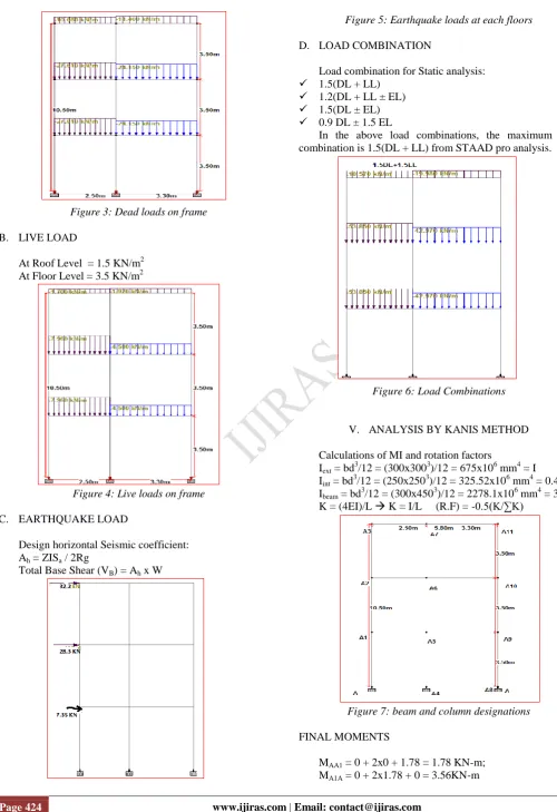
Figure 3: Dead loads on frame
B. LIVE LOAD
At Roof Level = 1.5 KN/m2 At Floor Level = 3.5 KN/m2
Figure 4: Live loads on frame
C. EARTHQUAKE LOAD
Design horizontal Seismic coefficient: Ah = ZISa / 2Rg
Total Base Shear (VB) = Ah x W
Figure 5: Earthquake loads at each floors
D. LOAD COMBINATION
Load combination for Static analysis: 1.5(DL + LL)
1.2(DL + LL ± EL) 1.5(DL ± EL) 0.9 DL ± 1.5 EL
In the above load combinations, the maximum load combination is 1.5(DL + LL) from STAAD pro analysis.
Figure 6: Load Combinations
V. ANALYSIS BY KANIS METHOD
Calculations of MI and rotation factors
Iext = bd3/12 = (300x3003)/12 = 675x106 mm4 = I
Iint = bd3/12 = (250x2503)/12 = 325.52x106 mm4 = 0.482I Ibeam = bd
3
/12 = (300x4503)/12 = 2278.1x106 mm4 = 3.37I K = (4EI)/L K = I/L (R.F) = -0.5(K/∑K)
Figure 7: beam and column designations
FINAL MOMENTS
Page 425 www.ijiras.com | Email: [email protected] MA1A2 = 0 + 2x1.78 + 1.78 = 5.34KN-m;
MA2A1 = 0 + 2x1.78 + 1.78 = 5.34KN-m MA2A3 = 0 + 2x1.78 + 0.371 = 3.931KN-m MA3A2 = 0 + 2x0.371 + 1.78 = 2.522KN-m MA4A5 = 0 + 2x0 + 0.441 = 0.441 KN-m MA5A4 = 0 + 2x0.441 + 0 = 0.882 KN-m MA5A6 = 0 + 2x0.441 + 0.4 = 1.282 KN-m MA6A5 = 0 + 2x0.4 + 0.441 = 1.241 KN-m MA6A7 = 0 + 2x0.4 + 0.51 = 1.31 KN-m MA7A6 = 0 + 2x0.51 + 0.4 = 1.42 KN-m MA8A9 = 0 + 2x0 + (-3.82) = -3.82 KN-m MA9A8 = 0 + 2x(-3.82) + 0 = -7.641 KN-m MA9A10 = 0 + 2x(-3.82) + (-3.58) = -11.22 KN-m MA10A9 = 0 + 2x(-3.58) + (-3.82) = -10.98 KN-m MA10A11 = 0 + 2x(-3.58) + (-1.874) = -9.031 KN-m MA11A10 = 0 + 2x(-1.874) + (-3.58) = -7.66 KN-m MA1A5 = -27.78 + 2x7.58 + 3.675 = -8.945 KN-m MA5A1 = 27.78 + 2x(3.675) + 7.58 = 42.71 KN-m MA2A6 = -27.78 + 2x7.57 + 3.37 = -9.27 KN-m MA6A2 = 27.78 + 2x3.37 + 7.57 = 42.09 KN-m MA3A7 = -9.67 + 2x(1.95) + 3.38 = -2.47 KN-m MA7A3 = 9.67 + 2x(3.38) + 1.95 = 18.22 KN-m MA5A9 = -39 + 2x(2.79) + (-11.46) = -47.88 KN-m MA9A5 = 39 + 2x(-11.46) + 2.79 = 18.87 KN-m MA6A10 = -39 + 2x2.56 + (-10.76) = -44.64 KN-m MA10A6 = 39 + 2x(-10.76) + 2.56 = 20.04 KN-m MA7A11 = -18.13 + 2x2.5 + (-6.64) = -19.77 KN-m MA11A7 = 18.13 + 2x(-6.64) + 2.5 = 7.35 KN-m
VI. DESIGN OF RCC ELEMENTS
The RCC elements are slab, beam, column, footing and stair case etc…
A. DESIGN OF SLAB
Slabs are most widely used structural elements forming floor and roof of building. Slab support mainly transverse load and transfer them to supports by bending actions more or one directions. On the basis of spanning direction: It is two type one way slabs and two way slab.
ONE WAY SLAB: When the slab is supported on two
opposite side parallel edges, it spans only in the directions perpendicular to the supporting edges. It bends in one directions and main steel is provided in the directions of the span. Such a slab is known as one- way slab.
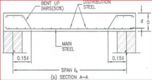
Figure 8: Reinforcement detailing in one-way sab
TWO WAY SLAB: When the is supported on four edges
and the load distribution is also on four edges of the panel. The reinforcement is provided on both the sides. Such slab is known as two way slab.
Figure 9: Reinforcement detailing in two-way sab
B. INTENSITY OF LOADS ON SLABS
AT ROOF LEVEL
D.L = 5 KN/m2 L.L = 1.5 KN/m2
T.L = 1.5 x (D.L+L.L) = 1.5 x (5+1.5) = 9.75 KN/m2
AT FLOOR LEVEL
D.L = 3.5 KN/m2 L.L = 3.5 KN/m2
W = 1.5 x (D.L+L.L) = 1.5 x (3.5+3.5) = 10.5 KN/m2
Formula for calculation of loads and moments Wx = W x lx, Wy = W x ly
Mx = αxWxlx2 My = αyWylx2 Area of steel:
Mu= 0.87fyAstd(1- (Astfy/bdfck))
VII. DESIGN OF BEAM
There are two types of reinforced concrete beams Single reinforced beams
Double reinforced beams
SINGLE REINFORCED BEAMS
In singly reinforced simply supported beams steel bars are placed near the bottom of the beam where they are effective in resisting in the tensile bending stress
DOUBLE REINFORCED BEAMS
It is reinforced under compression tension regions. The necessities of steel of compression region arise due to two reasons. When depth of beam is restricted. The strength availability singly reinforced beam is in adequate.
Page 426 www.ijiras.com | Email: [email protected] Area of steel:
Mu= 0.87fyAstd(1- (Astfy/bdfck))
CHECK FOR SHEAR
τv = Vu/bd τv < τc (O.K)
Figure 10: Reinforcement detailing at cross sectionsAA1
VIII. COLUMN
A column may be defined as an element used primary to support axial compressive loads and with a height of a least three times its lateral dimension. The strength of column depends upon the strength of materials, shape and size of cross section, length and degree of proportional and dedicational restrains at its ends.
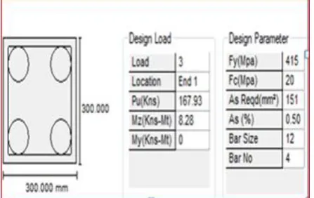
COLUMN PA8A9
Pu = 150 KN, Mu = 17.5 KN-m
b = 300 mm; D = 300 mm; fck = 20 MPa; d′ = 30 mm d′/D = 30/300 = 0.1
Mu/fckbd2 = (17.5x10⁶)/(20x300x3002) = 0.035 Pu/fckbd = (150x10
3
)/(20x300x300) = 0.08 From chart 32 of sp-16 ;
P/fck = 0.03 P = 0.03 x 20 = 0.6
Asc1 = PbD/100 = (0.6 x 300 x 300)/100 = 540 mm2 But Ascmin = 720 mm
2
provide ϕ = 16mm; Aϕ = π/4 x 162 = 201 mm2 n = 720/201 = 3.58 = 4
LATERAL TIES
Dia. not less than (i) ¼ x 16 = 4 mm (ii) 6mm Provide 6mm dia.
PITCH
Not more than (i) B = 300mm (ii) 16 x dia. = 256 mm (iii) 300 mm
Provide 260mm spacing
provide 4 no. of 16mmϕ bars longitudinal and 6mm lateral ties @ 260mm c/c
Figure 11: Reinforcement detailing at cross sectionsA8A9
IX. FOOTING
Foundations are structural elements that transfer loads from the building or individual column to the earth .If these loads are to be properly transmitted, foundations must be designed to prevent excessive settlement or rotation, to minimize differential settlement and to provide adequate safety against sliding and overturning.
CHECK FOR ONE WAY SHEAR (BEAM SHEAR)
The critical section for one way shear is at a distance„d‟ from the face of the column
CHECK FOR TWO WAY SHEAR (PUNCHING SHEAR)
The critical section for two way shear is at a distance „d/2‟ from the face of the column
X. DESIGN OF STAIR CASE
The purpose of a stair case to provide access to pedestrian in a building. The geometrical forms of staircase may be quite different depending on the individual circumstances involved.
Assume straight stair, supported on wall at one side and by stringer beam on the other side.
Horizontal span = 1.2m Rise = 150mm
Thread = 300mm M20, Fe415
Live load = 3 KN/m2 (residential building)
XI. ANALYSIS AND DESIGN OF A BUILDING USING STAAD PRO
PROCEDURE
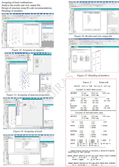
Draw plan and elevation based on dimensions of the site. Assigning of material properties and the elements. Assigning of supports.
Page 427 www.ijiras.com | Email: [email protected] Assigning of load combinations.
Analyze the results and view output file.
Design of structure using IS code recommendations. Detailing of members.
Figure 12: Assigning of supports
Figure 13: Assigning of material properties
Figure 14: Assigning of loads
Figure 15: Assigning of load combinations
Figure 16: Results and view output file
Page 428 www.ijiras.com | Email: [email protected]
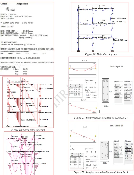
Figure 18: Shear force diagram
Figure 19: Bending moment diagram
Figure 20: Defection diagram
Figure 21: Reinforcement detailing at Beam No 14
Page 429 www.ijiras.com | Email: [email protected] XII. CONCLUSIONS
Short term deflection of all horizontal members is within 20mm.
The structural components of the building are safe in shear and flexure.
Amount of steel provided for the structure is economic. There is no such large difference in analysis results of
STAAD Pro and Kani‟s method.
Designing using Software‟s like STAAD Pro reduces lot of time in design work.
Details of each and every member can be obtained using STAAD Pro.
All the List of failed beams can be obtained and also Better Section is given by the software.
Accuracy is Improved by using software
REFERENCES
[1] V.Varalakshmi, G. Shiva Kumar and R. Sunil Sarma, Analysis and Design of G+5 residential building, mini project report, Marri Laxman Reddy Institute of
Technology and Management, Dundigal, Hyderabad, India-2014.
[2] P. Jayachandran and S. Rajasekaran, Structural Design of Multi-story Residential Building for in Salem, India, mini project report, PSG College of Technology, Coimbatore, Tamil Nadu, India-2006.
[3] Mahesh Suresh Kumawat and L.G. Kalurkar, Analysis and Design of multistory building using composite structure-2014.
[4] Divya kmath, K.Vandana Reddy, Analysis and Design of reinforced concrete structures-A G+5 building model, mini project report, Gokaraju Rangaraju Institute of Engineering and Technology, Hyderabad, India- 2012. [5] Murty C.V.R. and Jain. S. K "A Review of IS-1893- 1984
Provisions on seismic Design of Buildings". The Indian concrete journal, Nov.1994.
[6] Sarkar P. Agrawal, R and Menon, D."Design of beam, columns joints under Seismic loadings" A review, Journal of structural engineering SERC, Vol.33. No.6. Feb.2007. [7] BIS-1893, Criteria for Earthquake resistant design of