Page 15 www.ijiras.com | Email: [email protected]
Experimental Study On Replacement Of Fine Aggregate By Waste Glass
With Adding Of UV Absorbing Tio2 In Mortar
T. Arunvaratharaj
Assistant Professor, Department of Civil Engineering, Roever Engineering College, Perambalur
R. Kamalahasan
C. Rambabu
D. Ramesh
R. Renganathan
Student, Department of Civil Engineering, Roever Engineering College, Perambalur
I. INTRODUCTION
In this project is deals about manufactured by cement mortar 1:3 grade and replacing fine aggregate by waste glass. The cube size is 70.6 x 70.6 x 70.6 (mm).The waste glass sieve size is 2.36mm.Large quantities of waste glass, especially in the form of empty bottles are thrown away as garbage and the quantity of such glass waste is likely to be on the increase as more & more food stuffs and drinks are sold in glass bottles and containers. The waste glasses are giving less sound from the surrounding area. Also the specific gravity of the waste glass is more when compared to the normal sand. So it is used in the bricks, concrete, etc., Using waste glass in the concrete construction sector is advantageous, as the production cost of concrete will go down. The amount of waste glass is gradually increased over the years due to an ever-growing use of glass products. Most of the waste glasses have been dumped into landfill sites. The land filling of waste
glasses is undesirable because they are not biodegradable, which makes them environmentally less friendly.
There is huge potential for using waste glass in the concrete construction sector. When waste glasses are reused in making concrete products, the production cost of concrete will go down (Topcu and Canbuz, 2004). Crushed glass or cullet, if properly sized and processed, can exhibit characteristics similar to that of gravel or sand.
Titanium dioxide (TiO2) is the best known phototcatalyst
and has been employed in almost studies. Immobilization of TiO2 has been introduced to replace the existing suspension
system. This is due to the main drawback from the suspension system that is formation of sludge which requires further purification steps thus resulting in difficulties to recycle the photocatalyst. Since past decades, researchers have taken variousapproaches to modify the TiO2 for a better
Page 16 www.ijiras.com | Email: [email protected] methods that have been developed to prepare the immobilized
TiO2.
Adding polymer as matrices has been widely used by researchers in immobilized TiO2 preparation to produce
photocatalyst with better strength, adsorption capability and surface morphology. Some examples of the widely used polymers are polyvinyl chloride (PVC) [1], polyethylene glycol (PEG) [2] and polyvinyl alcohol (PVA) [3].
Under certain state, polymers with carboxyl or hydroxyl groups particularly, will bond chemically with the hydroxyl groups on the surface of TiO2.
A. OBJECTIVES OF THE PROJECT STUDY
To study the compressive strength of cement mortar using crushed waste glass as partial and fully replacement for fine aggregate.
To study the compressive strength of cement mortar using waste glass powder as partial and fully replacement for fine aggregate and partial admixing of titanium di oxide in the cement mortar.
To Understanding, what is ultra violet light.
To testing the abilities of materials to absorb the ultra violet rays.
To Testing the properties of uv rays absorbing materials.
Determined the UV rays absorbing range of concrete coating material.
To produce the mortar as eco-friendly and recycled mortar one.
To motivate the usage of uv absorbing materials in all the places.
B. METHODOLOGY
GENERAL
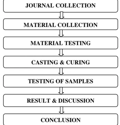
The various steps are involved in this project. So, the step by step procedure is given by the following flow chart.
Figure 1: Flow chart of methodology
II. MATERIALS A. CEMENT
Here the Ordinary Portland Cement (OPC) is used. The grade of the cement is 43.
B. SAND
The sand used was clean, sharp river sand that was free from clay, loam, dirt and organic or chemical matter of any description and was sand passing through 2.36mm zone of British standard test sieves. The sand had a specific gravity of 2.27 and its density is 3.72g/cc.
C. WASTE GLASS
The waste glass passing 2.36mm sieve and it is retained 450 microns sieve. The specific gravity of the waste glass is 3.03 and the density of the waste glass is 3.78 g/cc. Also the waste glass had the good sound resistance.
D. WATER
The water used was potable water, which was fresh, colorless, odorless and tasteless water that was free from organic matter of any type. The water is used for the construction work it’s also preparing a brick, curing, concrete, cleaning material, etc., the pH value is 6-7 only used.
E. TITANIUM DI OXIDE
Titanium Dioxide, when dried, contains not less than 99.0% of titanium dioxide (TiO2).
III. PREPARING MORTAR CUBES
Initially to prepare the mould in standard size 70.6x70.6x70.6mm. The mould is consists of the square shape in steel structure. After to prepare the mortar mix proportion.
The water content of the cement mortar mixing is 60% of cement weight. The mortar manufacturing is divided into three categories. They are without glass mixing, 50% of glass mixing and adding 5%, 10% and 15% of titanium di oxide, 100% of glass mixing and adding 5%, 10% and 15% of titanium di oxide mixing. The first category is without glass mixing. The cement weight is 0.135Kg. Then the sand weight is 0.410Kg.The mortar cube are manufactured as sixty three cubes. The second category is 50% of glass mixing. The cement weight is 0.135Kg. The titanium di oxide mixing with 5%, 10% and 15% to cement. That means the waste glass weight is 0.205Kg. The sand weight is 0.205Kg.
The third category is 100% of glass mixing. The cement weight is 0.135Kg. The waste glass weight is 100% of sand weight. That means the waste glass weight is 0.410Kg. The titanium di oxide mixing with 5%, 10% and 15% to cement. Finally the mortar are placed the mortar mould. The mould is coated by 220 hydraulic grade oil. Because it is used to easily remove from the mould.
JOURNAL COLLECTION
MATERIAL COLLECTION
MATERIAL TESTING
CASTING & CURING
TESTING OF SAMPLES
RESULT & DISCUSSION
Page 17 www.ijiras.com | Email: [email protected] A. CURING
After casting of cement mortar cube were stored in moulds for 24hours in moist condition at room temperature and then the moulds were carefully removed. The curing of the cast cubes of the two batches of mortar was carried out in the following sequence.
The manufacturing mortar are divided 3 days category. They are 7 days cubes, 14 days cubes, 28 days cubes. Curing process can be divided into three distinct stages. During stage one, the chemical reaction between the Portland cement and the water begins; however, the development of measurable compressive strength gain is minimal.
Depending on the particular mix design characteristics, this stage usually lasts for 3-4 hours. Stage two, beginning at the onset of initial set, is characterized by a rapid rate of hydration, resulting in exothermic heat development as well as rapid compressive strength gain.
Finally, after a majority of the cementations’ materials have reacted with water, stage three begins. During this time, less heat is generated by the hydration process, and a slower rate of strength development occurs, typically between 50 to 100 psi per hour. The application of elevated curing temperature has little effect on the rate of strength gain at this point.
Two basic approaches can be taken to affect the hydration process in order to achieve high early compressive strength in concrete. First, the environmental curing conditions can be altered in order to accelerate the process. The primary factor affecting the rate of hydration is the concrete curing temperature. Second, the cement composition can be specified in order to maximize the initial rate of compressive strength gain.
This can be adjusted through the type of cement used, as well as through the use of both mineral and chemical admixtures. A combination of these various methods is usually employed in order to create the most economical accelerated curing process possible.
IV. TESTING ON MORTAR CUBE
GENERAL
In, generally the testing carried out in the cubes are many. In this study concern, consider the following
A. COMPRESSIVE STRENGTH TEST
In the study of strength of materials, the compressive strength is the capacity of a material or structure to withstand loads tending to reduce size. It can be measured by plotting applied force against deformation in a testing machine. Some materials fracture at their compressive strength limit; others deform irreversibly, so a given amount of deformation may be considered as the limit for compressive load. Compressive strength is a key value for design of structures. Compressive strength is often measured on a universal testing machine
B. UV ABSORBING TEST
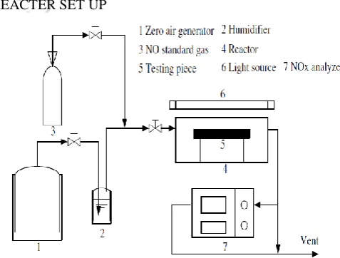
The reactor was made according to the specifications of JIS R1701-1 with slight modifications. The dimension of the reactor was700 mm in length, 400 mm in width and130 mm in height. Three 8W UV-A fluorescent lamps (TL 8W/08 BLB, Philips, Holland) were used to provide UV radiation. The wavelength of the lamps ranged from 300 to 400 nm with a maximum intensity at 365 nm. The UV lamps were positioned outside the reactor and the distance between the lamps and the reactor could be adjusted to achieve a required intensity.
The UV intensity was measured by a digital radiometer equipped with a DIX-365A UV-A sensor (Spectroline DRC-100X, spectronics corporation, USA). A zero air generator (Thermo Environmental Inc. Model 111) was used to supply the calibration gas. The testing gas was a mixture of zero air and standard NO (Arkonic Gases, Hong Kong). The humidity in the reactor was controlled by passing the zero air stream through a humidification chamber. The NO concentration was continuously measured using a Chemiluminescence NO analyzer (Thermo Environmental Instruments Inc. Model 42c, USA). A thermometer, a humidity sensor and an adjustable rack supporting specimens were placed inside the reactor. The reactor was completely sealed with no detectable leakage. Fig.3.5.2.1 shows a schematic diagramof the experimental set-up for this study.
REACTER SET UP
Figure 2: Schematic diagram of the experimental set-up
V. RESULT & DISCUSSION
Page 18 www.ijiras.com | Email: [email protected] The compressive strengths of waste glass cement mortar
combinations samples at 50% and 100% of levels of replacement of crushed waste glass and admixture of Tio2 with 5%, 10% and 15% were approximately 9.4%, 7.3% and 1.8% compressive strength of control sample, respectively.
The normal cement mortar load capacity is 214.9KN.The waste glass cement mortar load capacity is 198.3KN of 50% waste glass and Tio2 mixing. The UV absorbtion range is 320 – 365 nm of 5% of Tio2 mixing. The normal cement mortar absorbtion range is lower than the Tio2 mixing cement mortar.
Mixing of 50% fine aggregate and 50% crushed glass
S.NO % of Tio2 Mix Size (mm) Area of Specimen
A (mm2)
Max. Compressive Load W(KN) C.S= W/A N/mm2
1 5 70.6 x 70.6 4984.36 135.2 27.12 2 10 70.6 x 70.6 4984.36 124.8 25.03 3 15 70.6 x 70.6 4984.36 93.6 18.77
Table 1: Compressive Test (7 Days)
S.NO % of Tio2 Mix Size (mm) Area of Specimen
A (mm2)
Max. Compressive Load W(KN) C.S= W/A N/mm2
1 5 70.6 x 70.6 4984.36 157.6 32.68 2 10 70.6 x 70.6 4984.36 148.8 29.85 3 15 70.6 x 70.6 4984.36 97.6 19.58
Table 2: Compressive Test (14 Days)
S.NO % of Tio2 Mix Size (mm) Area of Specimen
A (mm2)
Max. Compressive Load W(KN) C.S= W/A N/mm2
1 5 70.6x70.6 4984.36 198.3 39.78 2 10 70.6 x 70.6 4984.36 167.4 33.58 3 15 70.6 x 70.6 4984.36 112.6 22.59
Table 3: Compressive Test (28 Days) Conventional cement sand mortar cube
S.NO Days Size
(mm)
Area of Specimen A
(mm2)
Max. Compressive Load W(KN) C.S= W/A N/mm2
1 7 70.6 x 70.6 4984.36 130.8 26.21 2 14 70.6 x 70.6 4984.36 165.2 33.06 3 28 70.6 x 70.6 4984.36 214.9 43.12
Table 4: Compressive Test
Figure 3 Mixing of 100% crushed waste glass
S.NO % of Tio2 Mix Size (mm) Area of Specimen
A (mm2)
Max. Compressive Load W(KN) C.S= W/A N/mm2
1 5 70.6x70.6 4984.36 54.4 10.92 2 10 70.6x70.6 4984.36 73.6 14.77 3 15 70.6x70.6 4984.36 79.2 15.89
Table 5: Compressive Test (7 Days)
S.NO % of Tio2 Mix Size (mm) Area of Specimen
A (mm2)
Max. Compressi ve Load W(KN) C.S= W/A N/mm2
1 5 70.6 x70.6 4984.36 60.8 12.20 2 10 70.6 x70.6 4984.36 119.2 23.92 3 15 70.6 x70.6 4984.36 83.2 16.70
Table 6: Compressive Test (14 Days)
S.NO % of Tio2 Mix Size (mm) Area of Specimen
A (mm2)
Max. Compressi ve Load W(KN) C.S= W/A N/mm2
1 5 70.6 x70.6 4984.36 76.8 15.40 2 10 70.6 x70.6 4984.36 156.8 31.45 3 15 70.6 x70.6 4984.36 95.3 19.11
Table 7: Compressive Test (28 Days)
Figure 4
UV ABSORBING TEST
Figure 5
VI. CONCLUSION
This study showed that waste glass was not only able to be utilized in glass products but also benefits production by reducing firing temperatures. There was no major difference between window glass and waste glass being utilized in cement mortar products. In this project will be appear on economically and available materials are used only. It’s always eco friendly. Also it has strength and durability when compared to the normal cement mortar. It’s reducing noise pollution. The waste glass and Tio2 are more absorbing the
UV from the admosphere. So it is used high rise building and high UV and IR regions.
The compressive strengths of waste glass cement mortar combinations samples at 50% and 100% of levels of replacement of crushed waste glass and admixture of Tio2
Page 19 www.ijiras.com | Email: [email protected] and 1.8% compressive strength of control sample,
respectively.
The normal cement mortar load capacity is 214.9KN.The waste glass cement mortar load capacity is 198.3KN of 50% waste glass and Tio2 mixing.
The UV absorbtion range is 320 – 365 nm of 5% of Tio2 mixing. The normal cement mortar absorbtion range is lower than the Tio2 mixing cement mortar.
REFERENCES
[1] S. B. Park, B. C Lee and J. H. Kim, “Studies on mechanical properties of concrete containing waste glass aggregate,” Cement and Concrete Research, vol. 34, pp. 2181–2189, Dec. 2004.
[2] Recovered container glass, Specification for quality and guidance for good practice in collection. BSI Standard PAS 101, 2005.
[3] Specification for processed glass for selected secondard end markets. BSI Standard PAS 102, 2005.
[4] [Online]Available:http://www.wrap.org.uk/publications/R ecycledGlass MarketSt udyStandards2003.pdf
[5] I. B. Topcu and M. Canbaz, “Properties of concrete containing waste glass,” Cement and Concrete Research, vol. 34, pp. 267–274, Feb. 2004.
[6] N. G. Egosi, “Mixed broken glass processing solutions,” in Proc. Utilization of Waste Materials in Civil Engineering Construction Conf. USA, 1992.
[7] C. D. Johnson, “Waste glass as coarse aggregate for concrete,” Journal of Testing and Evaluation, vol. 2, pp. 344–350, Sept. 1998.
[8] O. Masaki, “Study on the hydration hardening character of glass powder and basic physical properties of waste glass as construction material,” Asahi Ceramic Foundation Annual Tech. Rep., 1995.
[9] S. B. Park, “Development of recycling and treatment technologies for construction wastes,” Ministry of Construction and Transportation, Seoul, Tech. Rep., 2000. [10] R. N. Swamy, “The alkali-silica reaction in concrete”, 2nd
ed. USA: Taylor & Francis, 2003, pp. 335.
[11] V. Corinaldesi, G. Gnappi, G. Moriconi, and A. Montenero, “Reuse of ground waste glass as aggregate for mortars,” Waste Management, vol.
[12] Agrios, A. G., Pichat, P., 2005. State of the art and perspectives on materials and applications of photocatalysis over TiO2. Journal of Applied Electrochemistry 35,655–663.
[13] Beeldens, A., 2007. Air purification by road materials: results of the test project in
[14] Antwerp. In: Baglioni, P., Cassar, L. (Eds.), RILEM Int. Symp. on Photocatalysis, Environment and Construction Materials-TDP 2007, Florence, Italy, pp. 187–194. [15] Bazant, Z.P., Zi, G., Meyer, C., 2000. Fracture mechanics
of ASR in concretes with waste glass particles of different sizes. Journal of Engineering Mechanics 126,226–232. [16] Chen, D., Li, F., Ray, A.K., 2001. External and internal
mass transfer effect on photocatalytic degradation. Catalysis Today 66, 475–485.