23
ARP PROTOCOL SEQUENCE ANALYSIS FOR INTRUSION
DETECTION SYSTEM
D.PARAMESWARI, DR. R.M. SURESH
Research Scholar,Mother Teresa Women’s University,Kodaikanal-624 101. Professor & Head, Computer Science & Engineering
RMD ENgineering College, Chennai, Tamil Nadu - 601206
Email : [email protected]
ABSTRACT
Information and communication technology facilitated the communication system in a sophisticated manner at the same time it challenges are increased from the illegal users. The communication process, user’s connectivity, violations of policy on access of information are handles through intrusion .Intrusion prevention is the process of performing intrusion detection and attempting to stop detected possible incidents. It focused on identifying possible incidents, logging information about them, attempting to stop them, and reporting them to security administrators. However, organizations use Intrusion detection and prevention system (IDPS) for other purposes, such as identifying problems with security policies, documenting existing threats, and deterring individuals from violating security policies. Now a days IDPSs have become a necessary addition to the security infrastructure of nearly every organization. In this paper describes about protocol sequences which is used to detect the intrusion on hybrid network and its attributes and recommend the standardized ARP protocol for the intrusion detection process.
Key word:Network Intrusion Detection system, Protocol analysis, ARP sequence, ARP-NIDS
1.0 INTRODUCTION
The modern information and communication Technology (ICT) system developed and facilitated many communication enhancement options for the up gradation of our living standards. The computer network is played vital role as a backbone of ICT. Many challenges are managed in this system. In the communication process, user’s connectivity, violations of policy on access of information are handles through intrusion. According to Peter, Intrusion detection is the process of monitoring the events occurring in a computer system or network and analyzing them for signs of possible incidents, which are violations or imminent threats of violation of computer security policies, acceptable use policies, or standard security practices.
2.0 INTRUSION DETECTION SYSTEM (IDS)
In recent years, dramatically increase the amount of data (text; images; audio; etc.) that available electronically on the Internet. Therefore, the hackers and intruder had made many successful attempts to bring down high-profile company networks and web services. Many methods have
been developed to secure the data over the network and over the Internet.Computer networks are usually protected by anti-virus software, firewall, and encryption, secure network protocols, password protection etc. Since it has been proven that a potential attacker can always find a way to attack a network. These systems are known as Intrusion Detection System (IDS) and are placed inside the protected network, looking for potential threats in network traffic and or audit data recorded by host.
3.0 REVIEW OF LITERATURE
Initially intruder attempts to break into an information system or performs an action not legally allowed, we refer to this activity as an
24 unsecured traffic, or exploiting the design flaw of specific protocols (Graham, 2002). An Intrusion Detection System is a system for detecting intrusions and reporting them accurately to the proper authority. Intrusion Detection Systems are usually specific to the operating system that they operate in and are an important tool in the overall implementation an organization’s information security policy (Jones and Sielken, 2000), which reflects an organization's statement by defining the rules and practices to provide security, handle intrusions, and recover from damage caused by security breaches.
There are two generally accepted categories of intrusion detection techniques: misuse detection and
anomaly detection. Misuse detection refers to techniques that characterize known methods to penetrate a system. These penetrations are characterized as a ‘pattern’ or a ‘signature’ that the IDS looks for. The pattern/signature might be a static string or a set sequence of actions. System responses are based on identified penetrations.
Anomaly detection refers to techniques that define and characterize normal or acceptable behaviors of the system (e.g., CPU usage, job execution time, system calls). Behaviors that deviate from the expected normal behavior are considered intrusions (Bezroukov, 2002; see also McHugh, 2001).
IDSs can also be divided into two groups depending on where they look for intrusive behavior: Network-based IDS (NIDS) and Host-based IDS. The former refers to systems that identify intrusions by monitoring traffic through network devices (e.g. Network Interface Card, NIC). A host-based IDS monitors file and process activities related to a software environment associated with a specific host. Some host-based IDSs also listen to network traffic to identify attacks against a host (Bezroukov, 2002; see also McHugh, 2001). There are other emerging techniques. One example is known as a blocking IDS, which combines a host-based IDS with the ability to modify firewall rules (Miller and Shaw, 1996). Another is called a Honeypot, which appears to be a ‘target’ to an intruder, but is specifically designed to trap an intruder in order to trace down the intruder’s location and respond to attack (Bezroukov, 2002).This approached is planned with network based sensors. So the intrusion can be detected based on the observation of protocol and its sequence analysis. Therefore we are going to discuss about various protocol definitions which is used and observed in this research.
4.0 PROTOCOLS
Protocols are set of rules that governing how data is transferred, compressed and presented over networks.There are many protocols, each one governing the way a certain technology works. A
network protocol defines rules and conventions
for communication between network devices. Protocols for computer networking all generally use packet switching techniques to send and receive messages in the form of packets. Network protocols include mechanisms for devices to identify and make connections with each other, as well as formatting rules that specify how data is packaged into messages sent and received. Some protocols also support message acknowledgement and data compression designed for reliable and/or high-performance network communication. Hundreds of different computer network protocols have been developed each designed for specific purposes and environments.
In general , The Internet Protocol family contains a set of related (and among the most widely used network protocols. Besides Internet Protocol (IP) itself, higher-level protocols like TCP, UDP, HTTP, and FTP all integrate with IP to provide additional capabilities. Similarly, lower-level Internet Protocols like ARP and ICMP also co-exist with IP. These higher level protocols interact more closely with applications like Web browsers while lower-level protocols interact with network adapters and other computer hardware. Here we are going to discuss few protocols which is observed over the network . The following part of the paper provides more details on various protocols and its functional services .
NetBIOS Session Service over TCP/IP (NBSS): NetBIOS Session Services are part of the NetBIOS over TCP/IP (NetBT) family of protocols and is used for server message block (SMB). This is both the port that NULL Sessions are established over and the port that file and printer sharing takes place on.
25
Simple Network Management Protocol (SNMP):
is the standard protocol developed to manage nodes (servers, workstations, routers, switches and hubs, etc) on an IP network. SNMP enables network administrators to manage network performance, find, solve network problems and plan for network growth. Network management systems learn of problems by receiving traps or change notices from network devices implementing SNMP.
Hypertext Transfer Protocol (HTTP) : The Hypertext Transfer Protocol (HTTP) is an application level protocol with the lightness and speed necessary for distributed, collaborative, hypermedia information systems. HTTP has been in use by the World-Wide Web global information initiative since 1990.HTTP is a request-response standard typical of client-server computing. In HTTP, web browsers or spiders typically act as clients, while an application running on the computer hosting the web site acts as a server. The client, which submits HTTP requests, is also referred to as the user agent. The responding server, which stores or creates resources such as HTML files and images, may be called the origin server. In between the user agent and origin server may be several intermediaries, such as proxies, gateways, and tunnels. HTTP is not constrained in principle to using TCP/IP, although this is its most popular implementation platform. Indeed HTTP can be "implemented on top of any other protocol on the Internet, or on other networks." HTTP only presumes a reliable transport; any protocol that provides such guarantees can be used.
Hypertext Transfer Protocol Secure (HTTPS):HTTP can run on top of TLS or SSL for secured transactions, which is called HTTPS. HTTPS is not to be confused with S-HTTP, a security-enhanced version of HTTP developed and proposed as a standard by IETF. HTTP interaction over an encrypted Secure Sockets Layer (SSL) or Transport Layer Security (TLS) connection. This ensures reasonable protection from eavesdroppers and man-in-the-middle attacks, provided that adequate cipher suites are used and that the server certificate is verified and trusted.
Internet Control Message Protocol (ICMP) is an integrated part of the IP suite. ICMP messages, delivered in IP packets, are used for out-of-band messages related to network operation or mis-operation. ICMP packet delivery is unreliable, so hosts can't count on receiving ICMP packets for any network problems.
CMP[1] relies on IP to perform its tasks, and it is an integral part of IP. It differs in purpose from transport protocols such as TCP and UDP in that it is typically not used to send and receive data between end systems. It is usually not used directly by user network applications, with some notable exceptions being the ping tool and traceroute.
TELNET is a TCP-based, application-layer, Internet Standard protocol for remote login from one host to another.TELNET is a client-server protocol, based on TCP, and clients generally connect to port 23 on the host providing the service (though like many protocols in use on the Internet, which port to use is fairly easy to change). Partly because of the design of the protocol and partly because of the flexibility typically provided by TELNET client programs, it is also possible to use a TELNET program to establish an interactive TCP connection to some other service on an Internet host. A classic use of this is telnetting to port 25 (where typically an SMTP server is to be found) to debug a mail server.
Spanning-Tree Protocol (STP), as defined in IEEE 802.1D, is a link management protocol that provides path redundancy while preventing undesirable loops in the network. For an Ethernet network to function properly, only one active path can exist between two stations. Loops occur in networks for a variety of reasons. The most common reason for loops in networks is a deliberate attempt to provide redundancy—in case one link or switch fails, another link or switch can take over.
VOIP Protocols : Voice over IP (VOIP) uses the Internet Protocol (IP) to transmit voice as packets over an IP network. Using VOIP protocols, voice communications can be achieved on any IP network regardless of whether it is Internet, Intranet or Local Area Network (LAN). In a VOIP enabled network, the voice signal is digitized, compressed and converted to IP packets and then transmitted over the IP network. VOIP signaling protocols are used to set up and tear down calls, carry information required to locate users and negotiate capabilities. The key benefits of Internet telephony are the very low cost; the integration of data, voice and video on one network; the new services created on the converged network; and simplified management of end user and terminals.
26 or simulation data, over multicast or unicast network services. Applications typically run RTP on top of UDP to make use of its multiplexing and checksum services; both protocols contribute parts of the transport protocol functionality. However, RTP may be used with other suitable underlying network or transport protocols. RTP supports data transfer to multiple destinations using multicast distribution if provided by the underlying network.
Address Resolution Protocol (ARP) is a protocol for mapping an Internet Protocol address (IP address) to a physical machine address that is recognized in the local network. In an Ethernet local area network, however, addresses for attached devices are 48 bits long. A table, usually called the ARP cache, is used to maintain a correlation between each MAC address and its corresponding IP address. ARP provides the protocol rules for making this correlation and providing address conversion in both directions. This is used to identify and monitor the packet communication across the network. This part of the work try to optimize and construct the ARP sequence to detect the Intrusion.
5.0 EXPERIMENTAL SPECIFICATION
The network consists of wired and wireless with internet, intranet, and extranet using LAN and WAN architectures to provide the services for the students, staff. This network used for file transfer(FTP), Remote access(TELNET), Active Directory Services(DNS), NETBIOS, Print server, IP telephony (Internal),Wireless Fidelity, Bluetooth, VPN , Email(IMAP), SMTP, E-Learning(Web server-HTTP) , PING-ICMP, etc services. While providing the above specified services the network response and its Quality of Services varies due to the protocols which is used for the specific service. To reach the maximum service utilization, existing services are observed based on its protocol in and between the networks. The architecture diagram in the appendix 1.
There are many protocols running over the network to facilitate various requests and services. In this study we considered few services and its related protocol for the observation and analysis to construct the packet sequence to detect the intrusion.
The following diagram show the Network architecture of hybrid academic networkwhich connect three academic department and four non academic departments. This network provides Teaching- learning and educational management
service over 3000 students and the faculties in the campus. This consist of LAN and the following technological configurations
This academic network is framed as three clusters to provide the educational services. For the effective administration and maintenance of this network services, the classification and cluster made in the department level. In this study, the academic network structure and its laboratories’ setup data communication and transformation architecture is adopted.
The network architecture constructed with modern technological equipments such as cisco switches(Core Switch)- 4503E, SAN-SWITCH-IBM-2005-16B, cisco-routers-1700,2800 series; Firewall-CISCO-ASA-5510, cisco IP phones encompass of CISCO-MCS-7800-KQGCY35-Pentium-D- 2.80GHz call manager. This also integrated with High end servers’ such as HP Proliant-DL380 -GB8639NHPS-Xeon 3.4Ghz; IBM-3850-99B5265-Xeon-3.5GHz ; DVR- Proline- DVR-UK; SAN SWITCH- A device that routes data between servers and disk arrays in a storage area network . Its’ 800 nodes are typically Conduit with UTP CAT-5, CAT-5E,CAT-6 and Fiber Channel switch made up of fiber multimode channels.
The established infrastructure integrated with wireless fidelity of various manufacturers. The network is enhanced with Video conferencing supported for inter and intra conferencing facility. There are many protocols are observed for the intrusion detection process to frame the sequence formation. But in this paper we are going to discuss the common sequence formation of the ARP protocol.
6.0 OBSERVATION AND FINDINGS ON FUNCTIONAL PROCESS OF ARP
27 address as its own returns a reply so indicating. ARP updates the ARP cache for future reference and then sends the packet to the MAC address that replied.Since protocol details differ for each type of local area network, there are separate ARP Requests for Comments (RFC) for Ethernet, ATM, Fiber Distributed-Data Interface, HIPPI, and other protocols.
There is a Reverse ARP (RARP) for host machines that don't know their IP address. RARP enables them to request their IP address from the gateway's ARP cache.
ARP packet structure
The Address Resolution Protocol uses a simple message format that contains one address resolution request or response. The size of the ARP message depends on the upper layer and lower layer address sizes, which are given by the type of networking protocol in use and the type of hardware or virtual link layer that the upper layer protocol is running on. The message header specifies these types, as well as the size of addresses of each. The message header is completed with the operation code for request (1) and reply (2). The payload of the packet
consists of four addresses, the hardware and protocol address of the sender and receiver hosts.
The principal packet structure of ARP packets is shown in the above table which illustrates the case of IPv4 networks running on Ethernet. In this scenario, the packet has 48-bit fields for the sender hardware address (SHA) and target hardware address (THA), and 32-bit fields for the corresponding sender and target protocol addresses (SPA and TPA). Thus, the ARP packet size in this case is 28 bytes.
Hardware type (HTYPE) : This field specifies the Link Layer protocol type. Example: Ethernet is 1. Protocol type (PTYPE) :This field specifies the upper layer protocol for which the ARP request is intended. For IPv4, this has the value 0x0800. The permitted PTYPE values share a numbering space with those for Ethertype.
Hardware length (HLEN) :Length (in octets) of a hardware address. Ethernet addresses size is 6. Protocol length (PLEN) :Length (in octets) of addresses used in the upper layer protocol. (The upper layer protocol specified in PTYPE.) IPv4 address size is 4.
Operation :Specifies the operation that the sender is performing: 1 for request, 2 for reply.
Sender hardware address (SHA) :Hardware (MAC) address of the sender.
Sender protocol address (SPA) :Upper layer protocol address of the sender.
Target hardware address (THA) :Hardware address of the intended receiver. This field is ignored in requests.
Target protocol address (TPA) :Upper layer protocol address of the intended receiver.
In the structure ARP header constructed in the following standards
Fig : ARP packet structure
Internet Protocol (IPv4) over Ethernet ARP packet
bit offset 0 – 7 8 – 15
0 Hardware type (HTYPE)
16 Protocol type (PTYPE)
32 Hardware address length (HLEN)
Protocol address length (PLEN)
48 Operation (OPER)
64 Sender hardware address (SHA) (first 16 bits)
80 (next 16 bits)
96 (last 16 bits)
112 Sender protocol address (SPA) (first 16 bits)
128 (last 16 bits)
144 Target hardware address (THA) (first 16 bits)
160 (next 16 bits)
176 (last 16 bits)
192 Target protocol address (TPA) (first 16 bits)
28
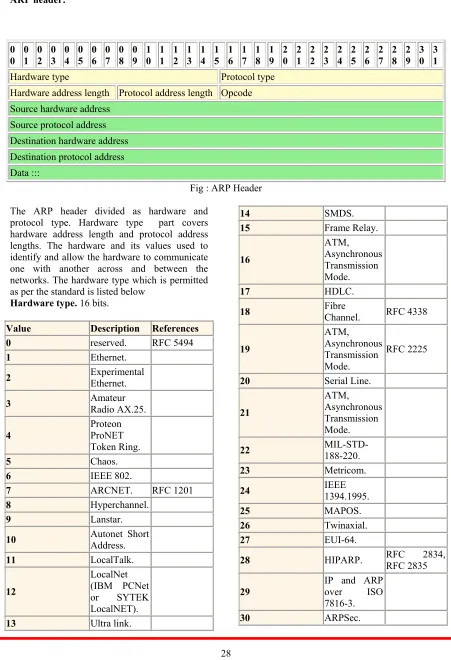
ARP header:
0
0 01 02 03 04 05 06 07 08 09 10 11 12 13 14 15 16 17 18 19 20 21 22 23 24 25 26 27 28 29 30 31
Hardware type Protocol type
Hardware address length Protocol address length Opcode Source hardware address
Source protocol address Destination hardware address Destination protocol address Data :::
Fig : ARP Header
The ARP header divided as hardware and protocol type. Hardware type part covers hardware address length and protocol address lengths. The hardware and its values used to identify and allow the hardware to communicate one with another across and between the networks. The hardware type which is permitted as per the standard is listed below
Hardware type. 16 bits.
Value Description References
0 reserved. RFC 5494
1 Ethernet.
2 Experimental Ethernet.
3 Amateur Radio AX.25.
4
Proteon ProNET Token Ring.
5 Chaos.
6 IEEE 802.
7 ARCNET. RFC 1201
8 Hyperchannel.
9 Lanstar.
10 Autonet Short Address.
11 LocalTalk.
12
LocalNet (IBM PCNet or SYTEK LocalNET).
13 Ultra link.
14 SMDS.
15 Frame Relay.
16
ATM, Asynchronous Transmission Mode.
17 HDLC.
18 Fibre Channel. RFC 4338
19
ATM, Asynchronous Transmission Mode.
RFC 2225
20 Serial Line.
21
ATM, Asynchronous Transmission Mode.
22 MIL-STD-188-220.
23 Metricom.
24 IEEE 1394.1995.
25 MAPOS.
26 Twinaxial.
27 EUI-64.
28 HIPARP. RFC 2834, RFC 2835
29 IP and ARP over ISO
7816-3.
29
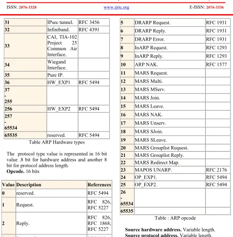
31 IPsec tunnel. RFC 3456
32 Infiniband. RFC 4391
33
CAI, TIA-102 Project 25 Common Air Interface.
34 Wiegand Interface.
35 Pure IP.
36 HW_EXP1 RFC 5494
37 -
255
256 HW_EXP2 RFC 5494
257 -
65534
65535 reserved. RFC 5494 Table ARP Hardware types
The protocol type value is represented in 16 bit value .8 bit for hardware address and another 8 bit for protocol address length.
Opcode. 16 bits
Value Description References
0 reserved. RFC 5494
1 Request. RFC 826, RFC 5227
2 Reply. RFC 826, RFC 1868,
RFC 5227
3 Request Reverse. RFC 903
4 Reply Reverse. RFC 903
5 DRARP Request. RFC 1931
6 DRARP Reply. RFC 1931
7 DRARP Error. RFC 1931
8 InARP Request. RFC 1293
9 InARP Reply. RFC 1293
10 ARP NAK. RFC 1577
11 MARS Request.
12 MARS Multi.
13 MARS MServ.
14 MARS Join.
15 MARS Leave.
16 MARS NAK.
17 MARS Unserv.
18 MARS SJoin.
19 MARS SLeave.
20 MARS Grouplist Request.
21 MARS Grouplist Reply.
22 MARS Redirect Map.
23 MAPOS UNARP. RFC 2176
24 OP_EXP1. RFC 5494
25 OP_EXP2. RFC 5494
26 -
65534
65535
Table : ARP opcode
Source hardware address. Variable length.
Source protocol address. Variable length.
Destination hardware address. Variable length.
Destination ARP probe
This exisitng ARP structure is not fixed for all the packets . The packet size varies from 42, 60,64,94,197 etc. To standardize the same the following ARP issues are addresses bellow
ARP probe :An ARP probe is an ARP request constructed with an all-zero sender IP address. The term is used in the IPv4 Address Conflict Detection specification (RFC 5227). Before beginning to use an IPv4 address (whether received from manual configuration, DHCP, or some other means), a host implementing this specification must test to see if
the address is already in use, by broadcasting ARP probe packets.
30 (THA) set to zero. An alternative is to broadcast an ARP reply with the sender's hardware and protocol addresses (SHA and SPA) duplicated in the target fields (TPA=SPA, THA=SHA).An ARP announcement is not intended to solicit a reply; instead it updates any cached entries in the ARP tables of other hosts that receive the packet. The operation code may indicate a request or a reply because the ARP standard specifies that the opcode is only processed after the ARP table has been updated from the address fields.Many operating systems perform gratuitous ARP during startup. That helps to resolve problems which would otherwise occur if, a network card was changed (changing the IP-address-to-MAC-address mapping) and other hosts still have the old mapping in their ARP caches. ARP announcements can be used to defend link-local IP addresses in the Zeroconf protocol (RFC 3927), and for IP address takeover within high-availability clusters
Gratuitous ARP is also used by some interface drivers to effect load balancing for incoming traffic. In a team of network cards, it is used to announce a different MAC address within the team that should receive incoming packets.
ARP mediation
ARP mediation refers to the process of resolving Layer 2 addresses when different resolution protocols are used on multiple connected circuits,.ATM on one end and Ethernet on the others.
Inverse ARP and Reverse ARP
The Inverse Address Resolution Protocol (Inverse ARP or InARP), is a protocol used for obtaining Network Layer addresses of other nodes from Data Link Layer (Layer 2) addresses. It is primarily used in Frame Relay (DLCI) and ATM networks, in which Layer 2 addresses of virtual circuits are sometimes obtained from Layer 2 signaling, and the corresponding Layer 3 addresses must be available before these virtual circuits can be used.
As ARP translates Layer 3 addresses to Layer 2 addresses, InARP may be described as its inverse. In addition, InARP is actually implemented as a protocol extension to ARP. It uses the same packet format from ARP; but has different operation codes.
Reverse Address Resolution Protocol (Reverse ARP or RARP) InARP, also translates Layer 2 addresses to Layer 3 addresses. However, while in
InARP the requesting station is querying the Layer 3 address of another node, RARP is used to obtain the Layer 3 address of the requesting station itself for address configuration purposes. RARP is now obsolete. It was replaced by BOOTP, which was later superseded by the Dynamic Host Configuration Protocol (DHCP).
As per the observation of around 800 system across the network and the detection more then ten lakhs of packets, the following are observed
ARP packets structure is not same The size of the SRP is differ
The packets are used to identify the device as well delivery the packets using its MAC and IP address The intrusion process , ARP played the vital role to access the device
7.0 STANDARDIZED 64 BYTE ARP PROTOCOL STRCUTURE
The above addressed issues are used one way to another to facilitate the communication process effectively . The communication facilitation allows the intrusion attacker to the network . To Monitor and detect the same users , the following sequence are proposed .
From 1-4 bytes (32 bit) Frame Information 1 2 3 4 Frame Info (0-31)
Time Number Length Capture Length
Link Data Data Data
The first byte represented about the frame information . This provides information about when the packets is travelled at that system or device,as well as number , length and capture of the packet .
5 6 7 8 9 10
Destination Address ( 32 - 79 ) Broad Cast
Group Address
Multi Cast Local Address
The next 48 bit ( 6 byte ) provides the information about the destination. If any of the destination is not listed with the specified network then that device will be blocked from the attached using GA algorithms.
11 12 13 14 15 16 Source ( 80 - 127 )
31 The next 48 bit ( 6 byte ) provides the information about the source. If any of the socuece not listed with the specified network then that device will be blocked from the attached using GA algorithms.
17 18 19 20 21 22 23 24 25 26 Type ARP
( 128 -
143) ARP ( 144 - 367 )
Hardw are
Type Protocol Type
Hard ware Size
Proto col Size
Op Cod e
This ten byte information provides more details about the ARP type , hardware and relateed information’s .The following sequence will provide data about the MAC address of the sender as well as target device .
27-30 31-36 37-40 41-46
ARP ( 144 - 367 ) Mac
Address Sender IP Target MAC Target IP
47-64
Trailer ( 368 - 511 )
8.0 FUTURE WORK DIRECTION
Using the proposed 64 byte ARP protocol architecture observe the packets to captured from the network . This packets are expected observe the protocol values as per the above specification and try to identify the intrusion .
9.0 Conclusion
This proposed standardized ARP 64 byte structure is easy to capture the ARP from the network. All the required information from the source and the sender as well as sender and target device are captured in this structure. This is not affected the data transformation process but this can be integrated to the monitor the nerwork. This paper is part the intrusion detection work using genetic algorithm .
REFERENCES:
[1]. Arizona.
http://www.acsac.org/1999/papers/fri-b-1030-sinclair.pdf (30 Oct. 2003).
[2]. Bezroukov, Nikolai. 19 July 2003. “Intrusion Detection (general issues).”
[3]. Bridges, Susan, and Rayford B. Vaughn. 2000. “Intrusion Detection Via Fuzzy Data Mining.” In Proceedings of 12th Annual Canadian Information Technology Security Symposium, pp. 109-122. Ottawa, Canada.
[4]. Crosbie, Mark, and Gene Spafford. 1995. “Applying Genetic Programming to Intrusion Detection.” In Proceedings of 1995 AAAI Fall Symposium on Genetic
Programming, pp. 1-8. Cambridge,
Massachusetts. URL: http://citeseer.nj.nec.com/crosbie95applyin
g.html (30 Oct. 2003).
[5]. David C. Plummer (1982-11). "RFC 826, An Ethernet Address Resolution Protocol -- or ---- Converting Network Protocol Addresses to 48.bit Ethernet Address for Transmission on Ethernet Hardware". Internet Engineering Task Force, Network
Working Group. http://tools.ietf.org/html/rfc826 .
[6]. http://csrc.ncsl.nist.gov/publications/nistpu
bs/800-94/SP800-94.pdf Guide to
Intrusion Detection and Prevention Systems (IDPS), NIST CSRC special publication SP 800-94, released 02/2007
[7]. http://www.geatbx.com/docu/algindex.htm l.
[8]. IANA - Ethertype values
[9]. IANA ARP - "Protocol Type"
[10]. Jones, Anita. K. and Robert. S. Sielken. 2000. “Computer System Intrusion Detection: A Survey.” Technical Report.Department of Computer Science, University of Virginia, Charlottesville, Virginia.
[11]. Li, Wei. 2002. “The integration of security sensors into the Intelligent Intrusion Detection System (IIDS) in a cluster environment.” Master’s Project Report. Department of Computer Science, Mississippi State University.
32 Engineering Institute, Carnegie Mellon University.
[13]. Miller, Brad. L. and Michael J. Shaw. 1996. “Genetic Algorithms with Dynamic Niche Sharing for Multimodal Function Optimization.” In Proceedings of IEEE International Conf. on Evolutionary
Computation, pp. 786-791. Nagoya
University, Japan.
[14]. Paxson, Vern. 1998. “Bro: A System for Detecting Network Intruders in Real-time.” In Proceedings of 7th USENIX Security Symposium, pp. 31-51. San Antonio, Texas.
[15]. Pohlheim, Hartmut. 30 Oct. 2003. “Genetic and Evolutionary Algorithms: Principles, Methods and Algorithms.”Genetic and Evolutionary Algorithm Toolbox. Hartmut Pohlheim.
URL:
[16]. RFC 1122, Requirements for Internet Hosts -- Communication Layers, R. Braden (Ed.), Internet Engineering Task Force (October 1989)
[17]. RFC 5342
[18]. Robert Graham. URL:
http://www.robertgraham.com/pubs/netwo rk-intrusion-detection.html (30 Oct. 2003).
[19]. Roesch, Martin. Nov. 7-12, 1999. “Snort - Lightweight Intrusion Detection for Networks.” In Proceedings of 13th Systems
Administration Conf. (LISA ’99), pp. 229-238.Seattle, Washington.
[20]. Sinclair, Chris, Lyn Pierce, and Sara Matzner. 1999. “An Application of Machine Learning to Network Intrusion Detection.” In Proceedings of 1999 Annual Computer Security Applications Conf. (ACSAC), pp. 371-377. Phoenix,
[21]. Sinclair,chris,Lynpierce and Sara Matznel,1999.”An application of Machine learning to network intrusion detection”, In proceedings of 1999 Annual Computer Society Applications Conference.pp-371-377.
[22]. Softpanorama: Open Source Software Educational Society. Nikolai Bezroukov. URL:http://www.softpanorama.org/Securit
y/intrusion_detection.shtml (30 Oct.
2003).