ISSN (e): 2250-3021, ISSN (p): 2278-8719
Vol. 09, Issue 12, December 2019, ||Series -II || PP 47-55
Seismic Responses of Panelled Beams with Different
Configurations Cover Large Circular Area
Hamady Hessian Ahmed*, Ahmed Abdel Raheem Farghaly**and Ahmed
Mohammed Talaat***
* ASS.PROF.DR. Faculty of Engineering. Civil Engineering Dept Assiut University, Assiut,Egypt ** ASS.PROF.DR. Civil and architecture structures, sohag University, Sohag, Egypt)
***M.Sc, Civil Engineering .Civil Engineering Dept Assiut University, Assiut,Egypt Received 20 December 2019; Accepted 03 January 2020
Abstract:
The big project requires special structures dive important of this project. The special architectural requirements for these projects need special structural design, for high performance in both dynamic and static cases. Panelled beams with circular edge beam has special behavior under seismic loads, with different panelled beams configurations with circular edge beam will be studied to make the most suitable panelled beams arrangement with acceptable performance under seismic loads. Six 3D panelled beams with circular edge beam with 6 stores with different panelled beams arrangements (skew panelled beams or perpendicular panelled beams configurations) studied to show the ideal performance of the structures subjected to earthquakes. Skewpanelled beams supported on circular beams for angles 30o, 45o and 60o are not suitable for those structures
subjected to earthquakes with comparison with perpendicular panelled beams supported on circular beam which performed well under seismic loads, and the panelled beams supported on circular beam resist tensional forces results from earthquakes.
Keywords:
gird system; panelled beams; circular beams; seismic performance; perpendicular panelled beams.
I.
INTRODUCTION
Grid floor system is a conventional method of construction in which beams will be spaced at regular intervals in perpendicular directions and monolithic with slab. They are generally employed for architectural reasons for large spaces such as auditoriums, theatre halls, where column and free space is often the main requirement.
El-Shaer, 2014 studied laterally loaded static and dynamic performance and comparison between three types of slabs systems (flat slab, ribbed slab, and panelled beam slab) used in high rise buildings and concluded that ribbed slab performed well under later static and dynamic load, but in flat slab cases suffer from punching shear, and panelled beams system is with moderate response.
Tzevelekas and Kontoni, 2016, studied building with flat slab system with different configurations subjected to earthquake and concluded that the shear wall combined with this system may give stiff system that reduce the straining actions with the low or moderate building with flat slab covering system.
Mishra, et al., 2015, studied HRB with different shear wall configurations subjected to earthquake and
concluded that the interior position of shear is more effective in resistance earthquake effects.
Hossain and Famiyesin, 2001, developed an equations constitute the primary database of an intelligent computer-aided-design system for accurate on arbitrary slabs which is capable of generating a secondary database through systems of interpolation and can be used for design assistance purposes. Johnson D., 1995, developed the analysis of torsion ally isotopically and showed that method effective for the analysis of three slabs of varying complexity.
Zeng et al. 2015 investigated vibration of train slab Track Bridge under vibration of the moving train
building with the high ductility requirements but the moment resisting frame with high ductility was not adequate for the medium-rise building and the sufficient amount of shear-walls to the system proved to be efficient way of providing the target performance of structure.
Guenaneche et al. (2019) evaluated plated RC beam and concluded that the interfacial stresses play a significant role in understanding this premature debonding failure of such repaired structures.
Ibraheem et al, (2014), analyzed L-shaped spandrel beams under eccentric concentrated load at mid-span to obtain a combined loading case: torsion, bending, and shear and concluded that the developed model can accurately predicted the loads and deflections for various types of reinforcements in spandrel beams, and captured the critical crack regions of these beams.
Rahmanian et al. (2014) summarized literatures on the optimization of reinforced concrete beams and suggested that nonlinear deterministic approaches can be efficiently employed to provide optimal design of RC beams.
Parrotta et al. (2014) studied the seismic behaviour of reinforced concrete beams experimentally and theoretically and concluded that the rheological effects can be important and must be accounted to understand the experimental results and the method of EC-2 tends to underestimate the tension-stiffening effects, leading to inaccuracies in the estimations of deflection and the results are agreement with the experimental results, showing the feasibility of the proposed modification.
Xiao et al. (2017) studied dynamic behaviours RC beams in the laboratory and discover that the effects of loading rates on the failure model and load-displacement curve of RC beams and on the cracking, ultimate, yield and failure strengths and displacements, ductility and dissipated energy capability of RC beams these results compared with 3D FEM of RC beams, which showed a great match.
Sucharda and Konecny, (2018), carried non-linear analysis of reinforced-concrete beams involving the tensile strength of concrete, fracture energy and the modulus of elasticity to compare old and new specifications based on the series of experiments which involve a large number of reinforcement, cross-section and span variants, which subsequently enabled a wider verification and discussion of the usability of the non-linear analysis and constitutive concrete model selected.
Models of multi-storey circular structures with different diameters without columns in the middle that variable were taken, including the dimensions of the dimensions of the beams and the distances between the beams were changed (2 m - 3 m - 4 m). In order to get architectural designs in unique architectural designs such as (meeting rooms, theaters, wedding halls, hotels with spaces and large spaces without columns in the middle the effect of earthquakes on the circular structures in various forms was examined to find the exact behavior under seismic loads. The effect of earthquakes on the structures was taken by changing the angles of the beams from 30 degrees to 45 degrees and 60 degrees. On the substitutions, the two directions were changed in the direction X, Y, where 2 x 4 m was used in the vertical direction (90° angle) and 3 x 4 m was used in the perpendicular direction (90° angle). Four types of known earthquakes (El-Centro, Chi Chi, Hollister, and Loma Prieta earthquakes) were used.
II.
MODEL DESCRIPTION
To find the effect of the earthquake on the response of grid beams with circular edge beam different cases of grid beams were studied with different configurations. To improve the effect of the earthquakes on the grid beams different configurations of panelled beams with circular edge beam studied but the internal divided
like the different angles between x and y directions grid beams three different angles used 30o, 45o and 60o (Fig.
a, b and c), and perpendicular grid beams with different portions distances 2x4m, 3x4m and 4x4m (Fig. 1-d, 1-e and 1-f). The columns also represented as frame elements with constant square cross sections 700x700m (to ignore the unsymmetrical effect) distributed on the perimeter of the circular edge beams of the models at
30° R15.00
45° R15.00
60° R15.00
R15.00
2.00 4.00
a) Skew 30o b) Skew 45o c) Skew 60o d) Perpendicular 2x4m
4.00 3.00 R15.00
Circular edge beam
R15.00
4.00 4.00
e) Perpendicular 3x4m f) Perpendicular 4x4m
Fig. 1: planes of the tested models.
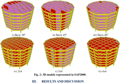
Figure 2 represented the 3D models of the tested models used in SAP2000. In SAP2000 grid beams represented by from elements (these elements response to moments in y directions, normal force, shear force and torsion force), and so the circular edge beams which the grid beams supported on them, the shell elements used to represent the slabs, the height of each floor 3m for all 7 floors model.
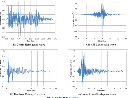
waves. The responses of the five models were measured for torsion, normal force, bending moment and lateral displacements.
-0.40 -0.30 -0.20 -0.10 0.00 0.10 0.20 0.30 0.40
0.00 5.00 10.00 15.00 20.00 25.00 30.00 35.00 40.00
Acc
el
er
ation
(m/Sec
.
2)
Time (Sec.)
-0.4 -0.3 -0.2 -0.1 0 0.1 0.2
0 10 20 30 40 50 60
Accele
rat
ion
(m/sec
2)
Time (Sec.)
i) El-Centro Earthquake wave ii) Chi Chi Earthquake wave
-0.15 -0.1 -0.05 0 0.05 0.1 0.15 0.2
0 5 10 15 20 25 30 35 40
Accele
rat
ion
(m/Sec.
2)
Times (Sec.)
-0.3 -0.2 -0.1 0 0.1 0.2 0.3 0.4
0 5 10 15 20 25 30 35 40
Accele
rat
ion
(m/Sec.
2)
Time (Sec.)
iii) Hollister Earthquake wave iv) Loma Prieta Earthquake wave
Fig. 3: Earthquakes waves.
0 3 6 9 12 15 18 21
-200 -150 -100 -50 0 50 100
Height
(m
)
Displacement (mm)
4x4 Skew 30 Skew 60 Skew 45 4x2 4x3
0 3 6 9 12 15 18 21
-400 -300 -200 -100 0 100 200 300 400
Height
(m
)
Displacement (mm)
4x4 Skew 30 Skew 60 Skew 60 Skew 45 4x2 4x3
i) ChiChi ii) Loma Prieta
0 3 6 9 12 15 18 21
-60 -40 -20 0 20 40 60 80 100
Hieght
(m
)
Displacement (mm)
4x4 skew 30 skew 60 skew 45 4x2 4x3
0 3 6 9 12 15 18 21
-300 -200 -100 0 100 200 300 400
Height
(m
)
Displacement (mm)
4x4 skew 30 skew 60 skew 45 4x2 4x3
iii) Hollister iv) El-Centro
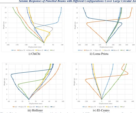
Fig. 4: Displacements due to different kinds of earthquakes and different panelled beam configurations.
Table 1 represents and defines the symbols used in the next part.
Table 1: Definitions of symbols used in the next curves.
Symbol Definition Symbol Definition
chi chi4
control case subjected to Chi Chi
earthquake chi chi S45
Skew 45 case subjected to Chi Chi earthquake
Loma Prieta4
control case subjected to Loma Prieta earthquake
Loma PrietaS45
Skew 45 case subjected to Loma Prieta earthquake
hollister4
control case subjected to Hollister earthquake
Hollister S45
Skew 45 case subjected to Hollister earthquake
El-centro4
control case subjected to El-Centro earthquake
El-centro S45
Skew 45 case subjected to El-Centro earthquake
chi chi S30
Skew 30 case subjected to Chi Chi
earthquake chi CHI 2
4x2 case subjected to Chi Chi
earthquake Loma
Prieta S30
Skew30 case subjected to Loma Prietaearthquake
Loma rieta2
4x2 case subjected to Loma Prieta earthquake
Hollister S30
Skew 30 case subjected to Hollister
earthquake Hollister 2
4x2 case subjected to Hollister
Figure 5 shows the base shear of the models subjected to different earthquakes and with different grid beams configurations, the response of the models show the values of each model to carry base shear under different earthquake kinds for skew30 and 4x3 cases look to carry more than the rest cases the control case and the rest cases carry small values of base shear with respect to skew30 and 4x3 cases.
0 5000 10000 15000 20000 25000 30000 chi chi4 loma prit a4 holl ister4 elce ntro4
chi chi S30
loma prit a S30 holl ister S30 elce ntro S30
chi chi S60
loma prit a S60 holl ister S60 elce ntro S60
chi chi S45
loma prit a S45 holl ister S45 elce ntro S45
chi CHI 2
loma prit a 2 hollis te r 2 elce ntro 2
chi chi 3
loma prit a 3 hollis te r 3 elce ntro 3 Base S hea r (K N)
Earthquake & Case
Fig. 5: Base shear under earthquakes loads with different panelled beam configurations.
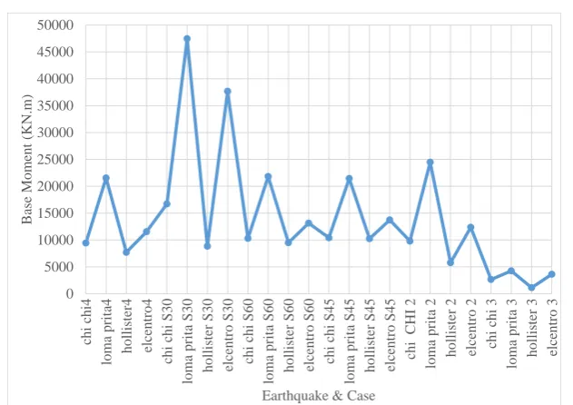
Figure 6 represents the base moments of the panelled beams with different configurations supported on circular edge beam subjected to different of earthquakes, all models carry nearly the same values of base moments except the skew 30 case with 2 times bigger than all cases.
0 20000 40000 60000 80000 100000 120000 140000 160000 chi chi4 loma prit a4 hollis te r4 elce ntro4
chi chi S30
loma prit a S30 hollis te r S30 elce ntro S30
chi chi S60
lom a prita S60 holl ister S60 elce ntro S 60
chi chi S45
loma prit a S45 hollis te r S45 elce ntro S45
chi CHI 2
loma prit a 2 hollis te r 2 elce ntro 2
chi chi 3
loma prit a 3 hollis te r 3 elce ntro 3 Base Norm al Force (KN )
Earthquake & Case
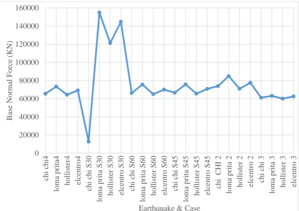
Fig. 6: Base Normal under earthquake loads and different panelled beam configurations.
0 5000 10000 15000 20000 25000 30000 35000 40000 45000 50000 chi chi4 loma prit a4 holl ister4 elce ntro4
chi chi S30
loma prit a S30 holl ister S30 elce ntro S30
chi chi S60
loma prit a S60 holl ister S60 elce ntro S60
chi chi S45
loma prit a S45 holl ister S45 elce ntro S45
chi CHI 2
loma prit a 2 hollis te r 2 elce ntro 2
chi chi 3
loma prit a 3 hollis te r 3 elce ntro 3 Base Mom ent (KN .m )
Earthquake & Case
Fig. 7: Base moment under earthquake loads and different panelled beams configurations.
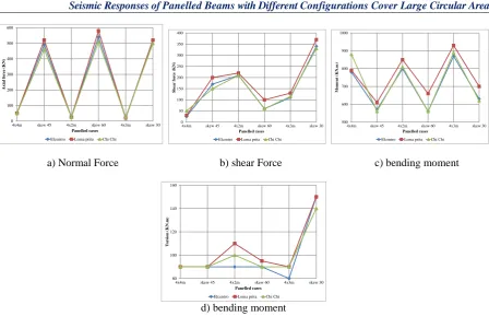
Figure 8 shows maximum forces in panelled beams with different configurations under seismic load, Fig. 8-a shows the maximum normal forces in the panelled beams it is clear that the perpendicular panelled beams supported on circular beam the normal forces nearly equals to zero but for skew panelled beams supported on circular beams the axial forces nearly equals to a specific value for the three different used earthquakes. Fig. 8-b represents the maximum shear force in panelled beams, the perpendicular panelled beams supported on circular beam recorded the minimum shear force compared with the corresponding cases of the skew panelled beams, all earthquakes used are show the same behavior, the maximum shear force are recoded in skew 30 panelled beams and the following case is skew 45 panelled beams. Fig. 8-c shows the maximum bending moment in different panelled beams configurations and different earthquakes, the maximum bending moments recorded in a perpendicular 4x4 then 4x3m and 4x2m panelled beams.
0 50 100 150 200 250
4x4m skew 45 4x2m skew 60 4x3m skew 30
Normal
for
ce
s
(KN)
Panelled beams cases
Elcentro Loma prita Chi Chi 20 40 60 80 100 120 140
4x4m skew 45 4x2m skew 60 4x3m skew 30
Sh
ear
for
ce
(KN)
Panelled beames cases
Elcentro Loma prita Chi Chi 1200 1250 1300 1350 1400 1450 1500 1550
4x4m skew 45 4x2m skew 60 4x3m skew 30
Mom
ent (KN.m)
Panelled beams cases
Elcentro Loma prita Chi Chi
a) Normal Force b) shear Force c) bending moment
Fig. 8: Maximum forces in panelled beams
0 100 200 300 400 500 600
4x4m skew 45 4x2m skew 60 4x3m skew 30
Axial for
ce
(KN)
Panelled cases
Elcentro Loma prita Chi Chi 0 50 100 150 200 250 300 350 400
4x4m skew 45 4x2m skew 60 4x3m skew 30
Sh
ear
for
ce
(KN)
Panelled cases
Elcentro Loma prita Chi Chi 500 600 700 800 900 1000
4x4m skew 45 4x2m skew 60 4x3m skew 30
Mom
ent (KN.m)
Panelled cases
Elcentro Loma prita Chi Chi
a) Normal Force b) shear Force c) bending moment
80 100 120 140 160
4x4m skew 45 4x2m skew 60 4x3m skew 30
T
orsion (
KN.
m)
Panelled cases
Elcentro Loma prita Chi Chi
d) bending moment
Fig. 9: Maximum forces in circular beam
IV.
CONCLUSIONS
The grid beams supported on circular beam behave different from these supported on straight edge beams. Six models 4x4 (control case). Skew 30, skew 45, skew 60, 4x2 and 4x3 analyzed under different kind of earthquakes to show the different behavior of each panelled beams configurations, the response of each models was measured by lateral displacements, base shear, base axial force, and base moments, from the time history analysis of each model under four different kinds of earthquakes the following conclusions can be drown out:
The displacements in the same plane of 4x4, 4x3 and 4x2 models are constant for all earthquakes.
The displacements for skew30, skew45 and skew60 in the same floor are not equals due to the inclinations
of panelled beams in different direction with connection with circular edge beams.
The displacements over the height of the models are nearly equals with smoothly interval, except for
skew30 and 4x3 cases which increased by nearly 1.3 to 1.5 times than control case with distortion in the models with height.
The base shear increase twice times for skew30 than control case and nearly for the rest of models either.
Base axial force for skew30 is bigger than control case by nearly 2 times all cases show a conversion values
with the control case.
A base moment for skew30 case is bigger than control case by 2.5 times all cases show oscillatory values
but also low than skew30 case.
The skew30 case with circular edge beam show a destructive behavior for both lateral displacements and
forces, but 4x3 model show destructive behavior for lateral displacements.
Maximum axial force and shear force in panelled beams occur in skew panelled beams case.
Maximum bending moment in panelled beams occurs in perpendicular panelled beams case.
Maximum axial force and shear force in circular edge beam occur in skew panelled beams case.
Maximum bending moment in circular edge beam occurs in perpendicular panelled beams case.
Maximum torsion in circular edge beam occurs in skew 30 panelled beams case.
Circular edge beam for panelled beams may improve the behavior of such structure spatially those
REFERENCES
[1]. El-Shaer M. A. A., (2014), “Seismic Load Analysis of Different R.C. Slab Systems for Tall Building“,
ACTA Tehnica Corviniensis – Bulletin of Engineering, VII(4), 65-74.
[2]. Guenaneche B., Benyoucef S., Tounsi A. and Adda Bedia E.A., (2019), “Improved analytical method for
adhesive stresses in plated beam: Effect of shear deformation”, Adv. Conc. Constr., 7(3), 151-166 DOI:
http://dx.doi.org/10.12989/acc.2019.7.3.151
Hossain K.M.A. and Famiyesin O.O.R., (2001), “An Intelligent System for the Design of RC Slabs”,
Struct. Eng. Mech., 12(3), 297-312. DOI: http://dx.doi.org/10.12989/sem.2001.12.3.297
[3]. Ibraheem O.F., Abu Bakar B.H. and Johari I., (2014), “Finite element analysis of reinforced concrete
spandrel beams under combined loading”, Comp. Conc., 13(2), 291-308
DOI: http://dx.doi.org/10.12989/cac.2014.13.2.291
[4]. Johnson D., (1995), “Automated Yield-Line Analysis of Beam-Slab Systems”, Struct. Eng. Mech., 3(6),
529-539.http://dx.doi.org/10.12989/sem.1995.3.6.529
[5]. Janghorban F. and Hoseini A., (2018), “Numerical Assessment of Post-Tensioned Slab-Edge Column
Connection Systems with and without Shear Cap”, Comput. Concrete, 22(1), 71-81.
https://doi:10.12989/cac.2018.22.1.071.
[6]. Mishra R.S., Kushwaha V. and Kumar S., (2015), “A Comparative Study of Different Configuration of
Shear Wall Location in Soft Story Building Subjected to Seismic Load” International Research Journal of
Engineering and Technology (IRJET), 02 (07), 513-519.
[7]. Parrotta J. E., Peiretti H. C., Gribniak V. and Caldentey A. P., 2014, “Investigating deformations of
RC beams: experimental and analytical study”, Comp. Conc., 13(6),
[8]. DOI: 10.12989/cac.2014.13.6.799
[9]. Rahmanian I., Lucet Y. and Tesfamariam S. (2014), “Optimal design of reinforced concrete beams: A
review”, Comp Conc, (13)4, 457-482 DOI: http://dx.doi.org/10.12989/cac.2014.13.4.457
Sucharda O. and Konecny P., (2018), “Recommendation for the modelling of 3D non-linear analysis of
RC beam tests”, Comp. and Conc., 21(1), 339-350
[10]. DOI: http://dx.doi.org/10.12989/cac.2017.20.3.339
[11]. Turker K and Gungor I, (2018), “Seismic performance of low and medium-rise RC buildings with
wide-beam and ribbed-slab”, Earth. and Struct., 15(4), 383-393
DOI: http://dx.doi.org/10.12989/eas.2018.15.4.383
[12]. Tzevelekas L. I. and Kontoni D-P N., (2016), “Evaluation of Seismic Vulnerability of Reinforced
Concrete Flat Slab Buildings”, 7th International Conference from “Scientific Computing to Computational Engineering” 7th IC-SCCE Athens,July.
[13]. Xiao S., Li J. and Mo Y.-L., (2017), “Dynamic bending behaviours of RC beams under monotonic
loading with variable rates”, Comp. Conc., 20(3), 339-350
DOI:http://dx.doi.org/10.12989/cac.2017.20.3.339
Xi K, Xing G, Wu T and Liu B, (2018), “Shear behavior of RC interior joints with beams of different
depths under cyclic loading”, Earth. and Struct., 15(2), 145-153 DOI:
http://dx.doi.org/10.12989/eas.2018.15.2.145
[14]. Zeng Z-P, He X-f, Zhao Y-g, Yu Z-w, Chen L-k, XuW-t and Lou P., (2015), “Random Vibration
Analysis of Train-Slab Track-Bridge Coupling System under Earthquakes”, Struct. Eng. Mech., 54 (5),