Vol. 06, Issue 03 (March. 2016), ||V2|| PP 04-08
Comparism of Attenuation Effect of Rainfall on Television Signal
With/Without (Atpc) Automatic
Transmit Power Control
Orji Hope E.
1, Udeh Ikemefuna J.
2, Offia Innocent S.
3Department of Electrical Electronic Engineering, Enugu State University of Science and Technology (ESUT)
Abstract: Attenuation by rain is a major constraint for transmission of microwave signal. The extreme of attenuation due to rain has brought forth the use of Automatic transmit power control ATPC) in microwave system. ATPC varies the transmitter power level (if there is any fluctuation in transmit power) in order to maintain the receiver signal level (CRSL) above the threshold for a desired result. This project discussed the design and performance analysis of ATPC in microwave link by simulating and obtaining measure values of the transmit power for better performance. Simulation is performed by analyzing the effect of ATPC to the transmitted signal level during raining and dry season of the year, the result shows that the ATPC was able to increase the dropped signal strength by 14%.
Keywords: ATPC (automatic transmit power control, dry season, raining season, microwave signals signal strength
I.
INTRODUCTION
It is know that adverse weather can affect quality of the television signal reception.
Typically, this occurs rarely, and only a short period depending on the duration of the rain. For the majority of users, it is heavy rains that can attenuate signal enough to result in noticeable degradation of major quality. In extreme cases, the reception can be effectively disrupted. Some of the factors that these problems depend upon include:
- Regional yearly “Rainfall” Figure - Location of the transmitter. - Height of the transmitter.
This is likely to be occurring more often in the regions with significant annual rainfall. What causes signal attenuation is mainly wave absorption by the rain drops. There is also some signal scattering due to refraction and diffraction of electromagnetic waves in and around rain drops very heavy snow can also affect signal quality, Richardson et al, 2004]. This paper x-rayed the rainfall effect on television signal transmission and its possible way it can be reduced
Under the condition of rain or snow, however the transmitted and received signals encounter extra attenuation and additional noise is introduced into the low-noise receiver on the ground.
A good knowledge of such rain effect is important for the prevention of the ground stations equipments which have to meet certain statistical requirement for transmission.
Telecommunication transmission facilities are physical means of communicating large amount of information over distance without exception; communication signals (speech, images, video, or computer data) are electromagnetic waves traveling along transmission lines such as two-wire line, coaxial line, optical fibre and microwave link. For a green route, the type of the amount of information to transmit the cost information which higher reliability than any other is transmitted by optic fiber.
The presence of the various forms of perception such as rain, snow, cloud and fog in a radio wave microwave path are always capable of producing major impairment to terrestrial communication. (Paraboni et al, 1998). ATPC refer to the process varying the transmit power in a microwave link with the presence of rain attenuation. In order to maintain the desired receive signal level. The ATPC system, the transmit power is adjusted by operation on a radio system frequency signal, which itself undergoes rain attractions .it is suitable to be used against propagation fading, with the environment is free from interference
at frequencies of above 10 GHz, the primary propagation impairment is rain. The spatio-temporal distribution of rain fields determines whether interfering links are attenuated in similar proportion to wanted links, thereby indicating if the implementation of ATPC will result in increased levels of interference. To accurately determine this, the spatio-temporal aspects of rain fields were investigated during the project, with the aim of producing a realistic rain field simulator to assist with the analysis of the impact of ATPC.
II.
FORMULATION OF AN EXPERIMENTAL SIMULATION MODEL
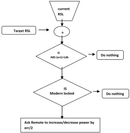
Structure of model formed to simulate the received signal strength
Fig 2.1: A diagram chart explaining the behavior of ATPC algorithm
Rain Attenuation: Heavy rain mostly results during the beginning of February and the end by the of October each year. Rain along the transmission path is the major effect for satellite communication at frequencies above 10 GHz. Rain attenuations is the weakening of the satellite signal as it passes through rain drops. Rain drops absorb and scatter radio wave energy; which degrades the reliability and performance of the communication link. Rain effects are dependent on frequency, rain rate, drop size distribution and drop shapes which are determined by the type of rain [Adami et al., 2002].
III.
METHODOLOGY
Automatic Transmit Power Control (ATPC) was design and implemented into the microwave link and the reading was observed and taken during dry and raining season. Rain measurement was measure using dip bucket.
Taking the measurement value of transmitted and received signal level with the installation of ATPC or without ATPC in the microwave link. Finally this method is design to provide the receiving signal strength level during rain and dry season and by this collected data show the impact of ATPC to restore the signal losses during attenuation by rain as shown in tables below. The triggering value of the ATPC is +30dB.
Data Collection: Data were collected from Nigerian Television Authority, NTA Enugu Nigeria from 2013 and current
RSL
+
IS ABS (err)>1db
IS Modern locked
Ask Remote to increase/decrease power by err/2
Do nothing
IV.
RESULTS
Table 2.1 show the cumulative data rain data against signal strength during dry season Month/dry
season
Average rainfall(mm)
Average signal strength ATPC
Jan 0.0 80.0 -
Feb 47.32 75.75 -
Nov. 2.0 76.5 -
Dec. 0.0 80.0 -
Dry season: = 0.0+47.32+2+0.0 = 2.4732/4 = 0.6183(m) Signal strength = 80.0+75.75+76.5+80.0 = 77.31(db)
Table .2.2 Shows Cumulative result of the rainy/dry season signal strength with and without ATPC
V.
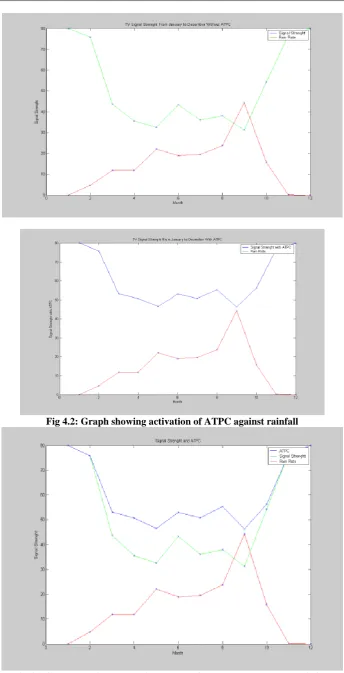
SIMULATION RESULT
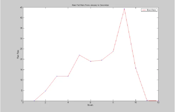
Fig 4.1 Graph showing rainfall Fig.3.2 graph of rain against signal strength with the ATPC not activated Month/Rainy
season
Average rainfall(mm)
Average signal strength(db)
ATPC
March 0.1184 43.75 53.15
April 0.1181 35.5 50.69
May 0.2202 32.5 46.49
June 0.1898 43.25 53.01
July 0.1954 36.0 50.85
August 0.2374 38.0 55.35
September 0.4432 31.25 46.34
Oct. 0.1546 54.25 56.23
4.1 DATA ANALYSIS
From the simulation in figures 4.1,4.2,4.3,4.4 it can be seen that the ATPC compensate the signal level dropped during the rainfall. When the RSL drops below threshold level, the ATPC is activated. The ATPC will be in inactive region when the RSL is above threshold level. The simulation identified that a high signal strength level could be transmitted by the transmitter. However the practical system will not transmit high signal level all the time since the ATPC will only be activated when the RSL drops below threshold level of +30dB.
VI.
CONCLUSION
With the detailed description of the experimental set up for ATPC-testing with real time rain fades signal identifies the response of system on rain fading. From the result the introduction of ATPC does give rise to a number of additional outages in the presence of intense rain Simulation is performed by analyzing the effect of ATPC to the transmitted signal level during raining and dry season of the year, the result shows that the ATPC was able to increase the dropped signal strength by 14%. In other words it can be concluded that ATPC offers better stability to signals transmission. Because rain is not only the attenuation effect on transmission of television signal, there are other factors that can affect transmission of signal during rain such as lightening, thunder and wind. Therefore we recommend that future work be carried out to see how to combat these factors for achieving stronger and better signal during transmission especially in raining seasons.
REFERENCES
[1]. Ashok Kumar and Hudiara I.S. (2002) “Measurement of rain induced attenuation of microwave at 19.4GHz IEEE Antenna and wireless propagation letters (AWPL), USA, Vol. 1. Issue 4, pp. 84-86.University
[2]. Asuan – Jung Su and Geraniotis, E. (2002). “Adaptive Closed loop power control with Quantized feedback and look filtering. “ Wireless Communications, IEEE Transaction on, Volume 1 Issue: 1. 76-86. [3]. Gane Robert K. (2012) “Electromagnetic wave propagation through Rain”, John Willey & Sons, Inc.,
New York. Pp. 54-64
[4]. Han, D., and Jia-Jin, L. (2001), Attenuation measurement: Report for rock physicis consortium pp. 2-5 . [5]. Jeong, J., D.E. Culler & J.H. Oh, (2005) “Empirical Analysis of transmission power control Algorithm
for wireless Sensor Network. In Technical Report No. UCB/EEeS
[6]. Kubish M., Karl .H., Wolisz, L.C. Zhong and et al March (2003), Distributed Algorithms for transmission power control in wireless sensor Network, In IEEE WCNC.
[7]. Ippolito L.J. (1986) “Radio wave propagation in satellite communication, Nostrand Reinhold Van Company”, New York. Pp 24-28.
[8]. Teknologi Malaysis, Skudai, (2000) “Final Report: Rain Attenuation studies for Communication System Operating in Tropical Regions, Pg 15-19.
[9]. Rafigual M.I and Tharek A.R., (2010) “One year measurement of rain attenuation of microwave signal at 23GHz, the 4th CDMA International Conference (CIC’99), Seoul, Korea, September 8 – 11.
[10]. Restrepo, J., L.D. Emiliani, and C. Fraoigue – Mendez. (2002) “Rain Attenuation predication in tropical zones. Theoretical of IEEE Information theory, Vol. 45, No. 3, pp 878 – 897.
[11]. Zhu, Y., and Tsvankin, I. (2004), Plane-wave propagation and radiation pattern in extenuative Ti media: CWP Project Review, CWP – 479, pp, 125-142.
[12]. Vigants A., (1975), “Space diversity Engineering,” The Bell System Technical, Vol. 54, No. 1, pp. 103-142.
[13]. Park S.J. Park and R. Sivakumar (2002) “Load-sensitive Transmission Power Control in Adltoc Network, IEEE Globecom, Vol. 1, pages 42-46.
[14]. Ramanathan R. an R.R.-Hain (2000) “Topology Control of Multihop wireless Network using Transmit Power Adjustment. In IEEE Infocom Vol. 2, Pages 404 – 413.
[15]. Robert K. Cran (1980) “prediction of Attenuation by Rain”, IEEE Transaction on Communication, Vol. Com 28, No. 9, 1717-1733.