Abstract— The Automatic Voltage Regulator (AVR) is widely used in industrial application to obtain the stability and good regulation of different electrical apparatus. In order to get output of the alternator, the field excitation is controlled by the AVR. The AVR maintains the constant voltage up to certain level of the load current which is independent of the generator speed and load. In this paper, the excitation control for the synchronous generator is designed by using silicon controlled rectifier (SCR) in order to improve the overall effectiveness of the synchronous generator. The control strategy is aimed to generate and deliver power to the interconnected system economically and reliably while managing the voltage and field current within set limitations. This includes a more accurate measurement of voltage and current, as well as improving the response time and system stability.
Index Term— AVR, Synchronous Generator, Stabilizer, Synchronizing Pulse Generator.
I. INTRODUCTION
A voltage regulator is an electrical regulator designed to automatically maintain a constant voltage level. It may use an electromechanical mechanism, or passive or active electronic components. Depending on the design, it may be used to regulate one or more AC or DC voltages. With the exception of passive shunt regulators, all modern electronic voltage regulators operate by comparing the actual output voltage to some internal fixed reference voltage. Any difference is amplified and used to control the regulation element in such a way as to reduce the voltage error. This forms a negative feedback control loop; increasing the open-loop gain tends to increase regulation accuracy but reduce stability (avoidance of oscillation or ringing during step changes). There will also be a trade-off between stability and the speed of the response to changes. If the output voltage is too low (perhaps due to input voltage reducing or load
current increasing), the regulation element is commanded up to a point to produce a
M. Rabiul Alam is with the School of Computer Science and Engineering, University of Information Technology and Sciences, Dhaka,
Bangladesh (e-mail: alam2007@ mail.ru).
Rajib Baran Roy is with the School of Computer Science and Engineering, University of Information Technology and Sciences, Dhaka,
Bangladesh (e-mail: [email protected]).
S.M. Jahangir Alam is with the Department of Mechanical and Electrical Engineering, School of Physics, Mechanical & Electrical Engineering, Xiamen University, China ; and also with the School of Computer Science
and Engineering, University of Information Technology and Sciences, Dhaka, Bangladesh (e-mail: jahangir_uits@ yahoo.com). Dewan Juel Rahman is with the School of Computer Science and Engineering, University of Information Technology and Sciences, Dhaka,
Bangladesh (e-mail:[email protected]).
higher output voltage by dropping less of the input voltage (for linear series regulators and buck switching regulators or to draw input current for longer periods (boost type switching regulators); if the output voltage is too high, the regulation element will normally be commanded to produce a lower voltage. However, many regulators have over current protection; so that they will entirely stop sourcing current (or limit the current in some way) if the output current is too high, and some regulators may also shut down if the input voltage is outside a given range. The objective of this work involves developing a single phase Automatic Voltage Regulator for the synchronous machine for usage in laboratory. The control strategy is aimed to generate and deliver power to the interconnected system economically and reliably while managing the voltage and field current within set limitations. The design and construction of the firing circuit for the AVR have been complete and perfected. This will provide firing angle to control the rectifier circuit to a DC motor. The modern applications of voltage stabilizer include: Power conditioning for mobile production vehicles, Television, Radio transmitters, Computer controlled manufacturing plant, Refrigeration, Power regulation in multistoried buildings and offices, X-Ray scanning equipment, Shore power supplies, etc.
II. VOLTAGESTABILIZER
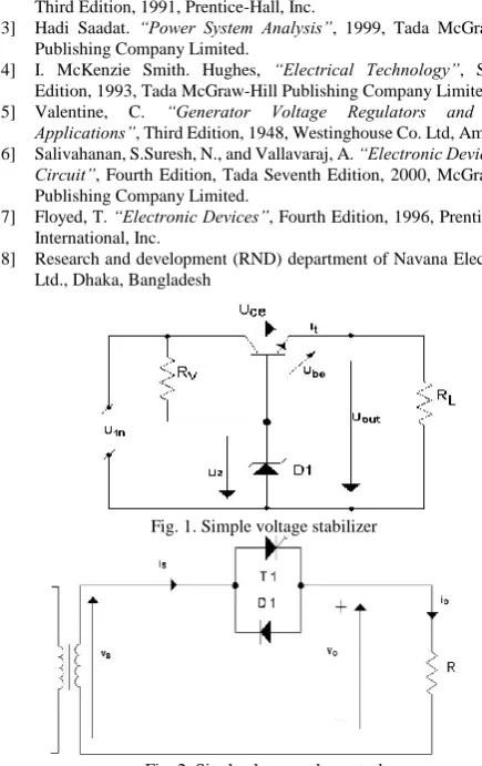
A voltage stabilizer is an electronic device able to deliver relatively constant output voltage while input voltage and load current changes over time [1]. In the simplest case emitter follower is used, the base of the regulating transistor is directly connected to the voltage reference. Fig. 1 shows a simple voltage stabilizer. The stabilizer uses the power source, having voltage Uin that may vary over time. It delivers
the relatively constant voltage Uout. The output load RL can
also vary over time. For such a device to work properly, the input voltage must be larger than the output voltage and voltage drop must not exceed the limits of the transistor used [1]. The output voltage of the stabilizer is equal to UZ - UBE
where UBE is about 0.7V and depends on the load current. If
the output voltage drops below that limit, this increases the voltage difference between the base and emitter (Ube),
opening the transistor and delivering more current. Delivering more current through the same output resistor RL increases the
voltage again. The voltage stabilizer is used to condition the fluctuating of AC power supply. There are two major types of voltage stabilizer: Solid state electronic (static) voltage stabilizer and Servo controlled (electro-mechanical) voltage stabilizer.
Static voltage stabilizer. Most of these voltage stabilizers have a transformer with various tapping and a control circuit that senses the input supply and accordingly the
Single Phase Automatic Voltage Regulator
Design for Synchronous Generator
output is taken from one of the tapping of the transformer. Usually static voltage stabilizers are used for domestic purposes (like refrigerators and air-conditioners) and for applications that are small and not very sensitive.
Servo voltage stabilizer. Servo voltage stabilizer comprises of a buck-boost transformer, a motor driven variable transformer, and a control circuit. When there is any variation in the input supply, the control circuit increases or decreases the voltage on the primary of buck-boost transformer, by controlling the variable transformer. The whole process is instantly done by constantly sensing the output voltage. Servo voltage stabilizers are used to provide stable voltage output even under extreme unbalanced voltage situations. These stabilizers are mainly used to protect the electrical and electronic equipments from being damaged due to high and low voltage. Actually they are voltage controllers and are used in various fields. They are extremely useful in processing plants. There are some servo stabilizers that also help to save energy to a greater extent.
Types of regulating unit. Devices, which may be operated as regulating units, can usually be used as controlling units. The regulating unit may be divided basically into two types: Discontinuous and Continuous control type of regulating unit. In case of the continuous control type of regulating unit the change of voltage produced by the regulating unit must be approximately proportional to the signal from the measuring unit in order to get continuous output signal. The regulating unit can be classified into two types: Electro-mechanical and Electrical.
AC Voltage Controller. When the power flow can be controlled by adjusting the value of ac voltage applied to the load by means of the thyristor, connected between the ac supply and the load is known as ac voltage controller. The ac voltage controllers can be classified into two types: Single-phase controller and Three-phase controller. For operation of the thysristor, two types of control are normally used: On-off control and Phase-angle control.
On-off control. In case of on-off control the thyristor connects the load to the ac source for a few cycle of input voltage and disconnects it for another few cycles. For this circuit, the thyristors are turned on at the zero voltage crossings of the ac input voltage. With zero voltage switching of thyristors, the harmonics generated by switching actions are reduced [2].
Phase control. In case of phase control, the thyristor connects the load to the ac source for a portion of each cycle of input voltage. The principle of phase control is shown in Fig. 2 by delaying the firing angle of the thyristor T1 which
controls the power flow to the load. The control range is limited and the effective rms output voltage can only be varied between 70.7 and 100% due to the presence of diode D1. The output voltage and the input current are asymmetrical
and contain a dc component. If there is an input transformer, it may be saturated.
DC drives. DC motors have variable speed
characteristics which are extensively used in variable speed DC drives. A converter is applied in the field circuit to control the field current by varying the delay angle. When the armature circuit of the dc motor is connected to a single-phase controlled rectifier output, the armature voltage can be varied
by adjusting the delay angle of the converter. The forced-commutated ac-dc converters can also be used to improve the power factor and reduce the harmonics.
III. AUTOMATIC VOLTAGE REGULATORFORSYNCHRONOUS GENERATOR
The operation of a generator is based on Faraday’s law of electromagnetic induction. If a coil or winding is linked to a varying magnetic field, then electromotive force or voltage is induced across the coil. Thus, a generator has two essential parts: one that creates a magnetic field and the other where the energy is induced. The field winding is excited by direct current conducted to it by means of carbon brushes bearing on slip rings or collector rings [5]. The rotor is also equipped with one or more short-circuited windings known as damper windings. The damper windings provide an additional stabilizing force for the machine during certain periods of operation. When a synchronous generator supplies electric power to a load, the armature current creates a magnetic flux wave in the air gap which rotates at synchronous speed. This flux reacts with the flux created by the field current and electromagnetic torque results from the tendency of these two magnetic fields to align. In a generator this torque opposes rotation and mechanical torque must be applied from the prime mover to sustain rotation. However, when the speed of the stator field and the rotor become different, currents are induced in the damper windings. Currents generated in the damper windings provide a counter torque.
Excitation control system. The excitation may be
provided through slip rings and brushes by means of DC generators mounted on the same shaft as the rotor of the synchronous machine. However, modern excitation systems usually use AC generators with rotating rectifiers, and are known as brush-less excitation [4]. The excitation system fulfils two main functions: it produces DC voltage (and power) to force current to flow in the field windings of the generator. There is a direct relationship between the generator terminal voltage and the quantity of current flowing in the field windings. It provides a means for regulating the terminal voltage of the generator to match a desired set point and to provide damping for power system oscillations. Varying the field excitation is an effect on power factor, armature current, power angle, voltage and reactive power flow.
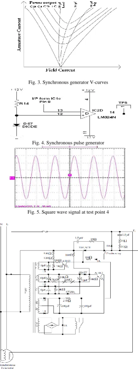
Power factor and armature current control. The power factor at which a synchronous machine operates and hence its armature current can be controlled by adjusting its field excitation. The relationship between armature current and field current at a constant terminal voltage and with a constant real power is shown in Fig. 3. This curve is called V curve because of its characteristics shape. The V curve and compounding curve constitute one of the generator's most important characteristics [4]. The output power of a synchronous generator is,
[3 * ] 3| || |cos
3 R VI V Ia
P
For constant developed power at a fixed V, Iacosθ must be
constant. Thus, the tip of the armature current phasor must fall on a vertical line. Reducing the excitation, caused the angle of the current phasor (and hence the power factor) to go from lagging to leading. Any reduction in excitation below the stability limit for a particular load will cause the rotor to pull out of synchronism.
Generator-type automatic voltage regulator. It is a control device which automatically regulates the voltage at the exciter of an alternator, to hold the output voltage constant within specified limits [4]. The design of the regulator will depend on: The characteristics of the driving source since changes in speed cause variations of voltage; The maximum and minimum load on the generator; The power factor of the load which will determine the range of required field current; The regulation of the generator; The magnetization curve of the generator and The characteristics of the exciter (if used).
IV. DIGITAL AUTOMATIC VOLTAGESTABILIZER
The automatic voltage regulator regulates the generator voltage is a device indispensable for operation, it is required to have superior reliability in addition to easy maintenance or repair features. There exists an ever increasing demand for improved system stability through the excitation control of the digital AVRs which is basically microprocessors based in order to prevent decline in system stability in line with the increase in power system and power rerouting. The digital automatic voltage regulator presents the following characteristics [5]: High function and high-performance control by using the 32-bit high-speed microprocessor in the main CPU; Improved easy operation and maintainability by using automatic system without human interfere; Improved reliability, space factor and overall economy due to use of programmable device and smaller size.
Automatic voltage regulator (AVR). Automatic voltage regulators consist of two units which are the measuring unit and the regulating unit. The function of the measuring unit is to detect a change in the input or output voltage of the automatic voltage regulator and producing a signal to operate the regulating unit. The purpose of the regulating unit is to act under the signal from the measuring unit in such a manner as to correct the output voltage of the regulator to a predetermined value. In some cases, a unit is required to control the regulating unit and this additional unit is needed which is known as the controlling unit. It is sometimes necessary to introduce another unit in order to prevent hunting. In all measuring units used in automatic voltage regulators, there is a reference voltage with which the input voltage is compared. The difference will be translated into the
output signal of the measuring unit. The accuracy of the measuring unit is direct dependent on the accuracy of the reference. Therefore the accuracy is the most important criteria for choosing a reference. Measuring units may be divided basically into two types: Discontinuous-control type of measuring unit and Continuous-control type of measuring unit. The measuring unit can be any one of three classes: Electromechanical, Electrical and a combination of Electrical and Electromechanical.
Technical specification of the AVR. The automatic
voltage regulator or stabilizer is fully automatic which gives protection to the valuable electronic equipments from high voltage. Due to the unstable nature of the power system the variation of supply voltage causes maloperation of different electrical and electronic equipments. Generally, the voltage regulation range of the stabilizer is 170 to 270 V but sometimes the voltage level comes down to 150 V and goes up to 300 V which is undesirable for the overall system. The maximum voltage variation level in any system is considered in designing the AVR [8].
Common specification: Output : 220V +/- nominal
Input : 130V~300V/40V~275V/ 90V~260V Burn out limit : 450V
Frequency : 50/60 Hz Wave Form : Sine wave
Protection : Protection against Sag, surge, Rf noise transient, Spike, impulse, Notch, Brown out etc. Humidity : 95%
Ambient temp : 55◦ C
LED indicator : Gray delivery/ Normal, Yellow> wait/ Delay, Red> High volt/ Danger, Red> fuse fail.
Model wise specification of AVR is given in the table 1.
TABLE I
MODEL WISE SPECIFICATION OF AVR
SN Model Capacity/Watt I/P range
01 NP 515 400VA / 320W 130~300V
02 NP 502 600VA / 480W 130~300V
03 NP 511 600VA / 480W 90~275V
04 NP 503 1000VA / 800W 130~300V
05 NP509 1200VA / 960W 130~300V
06 NP507 1500VA / 1200W 130~300V
07 NP506 2000VA / 1600W 130~300V
Application of the AVR. The AVR is widely used in computer, printer, medical equipment, refrigerator, TV, video & audio system, Fax, PABX, satellite receiver and other house hold appliances.
V. CONCEPTFORDEVELOPINGTHECIRCUIT
comparator amplifier is used to compare the output signal of the output amplifier with a linear ramp and pedestal wave shape. During the period of firing angle, this delay angle together with an electronic logic circuit is combined with an astable multi-vibrator to give a train of pulse that reduces the switching loss of thyristors. With this train of pulses, the converter, containing the SCRs can be used successfully to control its load. The triggering section comprises of different modules which are Synchronization and Phase angle control, Synchronizing pulse generator, Ramp generator, the comparator, Pulse generation. Upon completion of these modules, a full wave converter circuit is developed to test on the trigger section circuitry.
Synchronization and phase angle control. This section of the circuit consisted of an active filter and a high gain synchronous amplifier made out from the LM-324 chip. The active filter is tuned to 50Hz to ensure that no transients or electrical noise on the supply are interfering with the triggering operation. In principle this synchronizing input signal is a full wave rectified signal which is later used to generate firing pulses to thyristors which is fired during either the positive going half cycle or the negative going half cycle of the waveform [6].
Synchronizing pulse generator. The Fig. 4 shows the circuit module with a fixed voltage of 0.6 volt formed by the voltage divider R14 and D67, IC2D acts as a comparator comparing the rectified synchronous signal and this fixed voltage. The output waveform of the Fig. 5 shows the expected result is a square wave signal of short pulse duration. The duration of the pulse is dependent on the magnitude of the input signal [7]. In order to achieve compatibilities with the controller currently used in the laboratory, a circuit diagram of a single-phase controller circuit available in the laboratory was used as references. Therefore, modifications were made from that to produce a three phase AVR required for the closed loop system.
Signal processing circuit. For this section of the AVR, the feedback signal is being processed and fed back into the trigger section of the module [6]. From the converter, a DC voltage is fed into the voltage feedback amplifier module. This module will compare all the signals which influence the performance of the Thyristor Bridge. It compares the actual load current signal with the available reference voltage. The output signal is sent to the current amplifier module, which is an inverting amplifier with its feedback path completed by the entire module. The current limiter module is applied to decrease the current of the circuit to prevent overloading that may damage the system.
VI. DESIGN OFTHEAUTOMATICVOLTAGEREGULATOR Synchronous generator constant voltage at the generator terminals is essential for satisfactory main power supply. The terminal voltage can be affected by various disturbing factors (speed, load, power factor, and temperature rise), so that special regulating equipment is required to keep the voltage constant, even when affected by these disturbing factors [6]. Power system operation considered so far was under condition of steady load. However, both active and reactive power demands are never steady and they continually change with the rising or falling trend. Therefore, steam input to turbo
generators (or water input to hydro-generators) must be continuously regulated to match the active power demand, failing which the machine speed will vary with consequent change in frequency which may be highly undesirable. Also the excitation of generators must be continuously regulated to match the reactive power demand with reactive generation, otherwise the voltages of various system buses may go beyond the prescribed limits. The voltage regulator may be manually or automatically controlled. The voltage can be regulated manually by tap-changing switches, a variable auto transformer, and an induction regulator. In manual control, the output voltage is sensed with a voltmeter connected at the output; the decision and correcting operation is made by a human being [6].
In modern large interconnected system, manual regulation is not feasible and therefore automatic generation and voltage regulation equipment is installed on each generator. Automatic Voltage Regulator (AVR) may be discontinuous or continuous type. The discontinuous control type is simpler than the continuous type but it has a dead zone where no single is given. Therefore, its response time is longer and less accurate. Modern static continuous type automatic voltage regulator has the advantage of providing extremely fast response times and high field ceiling voltages for forcing rapid changes in the generator terminal voltage during system faults. Rapid terminal voltage forcing is necessary to maintain transient stability of the power system during and immediately after system faults. Response time variation can cause the AVR to degrade the system stability [6]. Electronic control circuit is now used for the field control circuit as the closed loop system to obtain stable output voltage. Electronic control circuit is simple but the simple is the best. By using this control circuit for the system, the system cost is decreased and system reliability and design flexibility are increased.
AVR Design for the synchronous generator. The circuit
arrangement of the field control circuit of the synchronous generator is shown in Fig.6. In this system, the output voltage of the generator is sampled through the transformer and is rectified by simple circuit and the bridge rectifier. In the initial state condition, the output of the generator may be 25V or 30V which depends on the electromagnetic field in the machine, at the time, the 12V relay is normally close position. At the time, the gate voltage is fed to the synchronous generator field coil until the output voltage is 230V. Now, 12V relay is normally open position [7]. When the mains supply voltage falls, Q2 produce negative current to the bridge
circuit and the bridge circuit supplies positive current to the gate of the SCR and the required current is fed to the field coil and the output voltage of the synchronous generator is increased. When the output is 230V, the output positive current of the bridge is balanced with the output negative current of the Q1. While the main supply voltage rises, Q2
response to this sample voltage, the AVR controls the power fed to the exciter field, and hence the main field, to maintain the machine output voltage within the specified limits. Compensating for load, speed, temperature and power factor of the generator. The AVR includes an optimized stability circuit to provide good steady state and transient performance of the generator [5].
List of components. Resistor: 100Ω,1KΩ,100
KΩ,2.2MΩ,8.2 KΩ,220 KΩ,33Ω,200 KΩ; Transistor: HA 2222, BC547A, BC546; IC: LM324: HEF4001B, LM124; SCR: BT150-500R.
Tests and results. These results are obtained by feeding the variable over or below the input voltage to the electronic control circuit and a field coil (100 watts bulb). The output of the generator voltage must be stable although the various input voltage pass through electronic control circuit. Results of field voltage and current are shown in the table 2.
TABLE II
RESULTS OF FIELD VOLTAGE AND CURRENT
Input Voltage
Output Voltage
Voltage Difference
Field Voltage (dc)
Field Current (dc)
190 230 -40 85 V 80.0mA
200 230 -30 75 V 65.0mA
205 230 -25 70 V 57.5mA
210 230 -20 65 V 50.0mA
215 230 -15 60 V 42.5mA
220 230 -10 55 V 35.0mA
225 230 -5 50 V 27.5mA
230 230 0 45 V 20.0mA
235 230 +5 40 V 12.5mA
240 230 +10 35 V 05.0mA
Future Work
Designing the circuit for three-phase AVR is complex than that of the single phase AVR. Some modifications are necessary for converting the single phase AVR into three-phase AVR. Three phase converters are extensively used in industrial applications. In case of three phase converter, three identical converters are connected together and the firing angle of each converter group is controlled. For proper synchronization of the input voltages with the output the triggering section needs to be carefully designed so that each SCR conducts over only 60 degrees and the firing angle is measured from point where successive line voltages cross. The output waveform is therefore made up of sections of six line voltage waveforms and therefore six pulse circuits are required. Though the AVR is designed for single phase application but it can be modified for three phase application. In that case of three phase application, some changes need to be considered for designing the control and switching section of this AVR.
VII. CONCLUSION
In industrial application, it is hard to find an automatic voltage regulator which provides constant output at a reasonable price therefore the main consideration of this work is to provide a constant output AVR at a reasonable cost. In this work, an AVR is designed for 10 KVA alternator’s field control. The standard servo controlled voltage stabilizers
handle a variation of more than 40% of the input voltage, while using AVR it is possible to design stabilizers which handle a voltage swing as high as 80% on the input. The designed AVR provides constant output voltage of 230 V for the input voltage variation of 190 to 240 V. The voltage difference for the designed AVR varies from -40 to +1 V, whereas the variation of the field voltage and field current varies within the range of 35 to 85 V and 5 to 80mA, respectively.
ACKNOWLEDGMENT
We would like to express sincere thanks to engineer Profulla Cahndra Sutradhar of Navana Electronics Ltd. We wish to extend our warmest thanks to all those who have helped us with this work, especially to engineer Atikur Rahman and engineer Golam Rahman. We also sincerely wish to acknowledge our gratitude to our colleagues and students of University of Information Technology and Sciences (UITS) for extending their help and assistance to complete this work.
REFERENCES
[1] Fitzgerald, Kingsley and Kusko. “Electric Machinery”, Third Edition, 1971, McGraw-Hill Kagakusha.Ltd.
[2] Hubert, C. “Theory Operation Maintance of Electrical Machine”,
Third Edition, 1991, Prentice-Hall, Inc.
[3] Hadi Saadat. “Power System Analysis”, 1999, Tada McGraw-Hill Publishing Company Limited.
[4] I. McKenzie Smith. Hughes, “Electrical Technology”, Seventh Edition, 1993, Tada McGraw-Hill Publishing Company Limited. [5] Valentine, C. “Generator Voltage Regulators and Their
Applications”, Third Edition, 1948, Westinghouse Co. Ltd, American. [6] Salivahanan, S.Suresh, N., and Vallavaraj, A. “Electronic Devices and
Circuit”, Fourth Edition, Tada Seventh Edition, 2000, McGraw-Hill Publishing Company Limited.
[7] Floyed, T. “Electronic Devices”, Fourth Edition, 1996, Prentice Hall International, Inc.
[8] Research and development (RND) department of Navana Electronics Ltd., Dhaka, Bangladesh
Fig. 1. Simple voltage stabilizer
Fig. 3. Synchronous generator V-curves
Fig. 4. Synchronous pulse generator
Fig. 5. Square wave signal at test point 4
Fig. 6. Overall circuit of AVR for the diesel engine type synchronous generator
M. Rabiul Alam, born in Kushtia, Bangladesh. He received Ph. D. (2004) in Technical Sciences and completed a two years Post doc (2006) in Energy Management and M. S. E. E. (1995) from Moscow State Mining University, Moscow, Russia.
M. Rabiul Alam is an Associate Professor of the Department of Electrical and Electronic Engineering and Head of the School of Computer Science and Engineering at University of Information Technology and Sciences (UITS), Dhaka, Bangladesh from 2010. From 2008 until 2010 he was interim Head of the School of Computer Science and Engineering and Head of the department of Electrical and Electronic Engineering at the same University. He was an Associate Professor of the Department of Electrical and Electronic Engineering at International University of Business Agriculture and Technology (IUBAT), Dhaka, Bangladesh in 2007–2008. He is the author of 6 publications. His field of interest is: Power Engineering, Renewable Energy and Energy Management.
Rajib Baran Roy, born in Dhaka, Bangladesh. He obtained his Bachelor’s in Electrical and Electronic Engineering from Chittagong University of Engineering (2001) and Technology, Bangladesh and M.S.E.E. (2008) from Flensburg University, Germany.
Rajib Baran Roy is an Assistant Professor and Head of the Department of Electrical and Electronic Engineering at University of Information Technology and Sciences (UITS), Dhaka, Bangladesh from 2010. From 2008 until 2010 he was a Lecturer of the Department of Electrical and Electronic Engineering Department at the same University. From 2001 until 2005 he worked in the Local Government and Engineering Department, Government of Bangladesh. He is the author of 3 publications. His field of interest is: Industrial and Power Engineering, Renewable Energy and Energy Management.
S.M. Jahangir Alam, born in Jessore, Bangladesh. He completed his B.Sc. in Computer Science and Engineering (2004) from Dhaka International University, Dhaka, Bangladesh and M.S. in Telecommunications (2006) from University of Information Technology and Sciences (UITS), Dhaka, Bangladesh. Now he is studying PhD in Electrical Engineering and Automation at Xiamen University, China.
S.M. Jahangir Alam was a Lecturer of Electronic and Communication Engineering and Coordinator of the School of Computer Science and Engineering at University of Information Technology and Sciences (UITS), Dhaka, Bangladesh from 2006 until 2010. He is the author of 3 publications. His field of interest is: Communication Engineering, Image Processing, Sensor, Digital Signal Processing, PID, and Automation.
Dewan Jewel Rahman, born in Narayangong Bangladesh. He completed his B.Sc. in Electronic and Communication Engineering (2011) from University of Information Technology and Sciences (UITS), Dhaka, Bangladesh.
Dewan Jewel Rahman is working as an Information and Communication Technology specialist at University of Information Technology and Sciences (UITS), Dhaka, Bangladesh. His field of interest is: Communication Engineering, Information Technology and Networking.