e- ISSN: 2278-067X, p-ISSN: 2278-800X, www.ijerd.com
Volume 15, Issue 3 (March 2019), PP.40-46
UHPFRC Columns under Eccentric Stresses
NedaaTaher
1*, EnasKhattab
2, SherifElwan
3, Ayman H. H. Khalil
41B.Sc. of Civil Engineering, Faculty of Engineering, Ain Shams University, Cairo, Egypt
2Associate Professor, Building Materials and Quality Control Research Institute, Housing & Building National Research Center, Cairo, Egypt
3
Associate Professor, Civil Engineering Department, the Higher Institute of Engineering at El-Shorouk, Cairo, Egypt
4Professor of Reinforced Concrete Structures, Structural Engineering Department, Faculty of Engineering, Ain Shams University, Cairo, Egypt
Corresponding Author: Nedaa Taher
ABSTRACT: This paper studies the performance UHPFRC columns loaded with eccentric compressive loads. The variables were the change in eccentricity and longitudinal reinforcement.
KEYWORDS: ultra high performance fiber reinforced concrete, eccentric loads, short columns, load capacity, polypropylene fibers.
--- --- Date of Submission: 30-09-2019 Date of acceptance: 15-10-2019 --- ---
I.
INTRODUCTION
Ultra high performance concrete fiber reinforced concrete (UHPFRC)is defined by being a fiber reinforced cement material with a compressive strength over 100 MPa, possibly exceeding 250 MPa. It is typically manufactured with low water to binder ratio, high fineness additives and no coarse aggregates, exhibiting a developed material with superior mechanical properties such as the very high compressive strength, the enhanced tensile strength, durability, toughness and impact resistance, which makes it with a suitable potential for using in structures with slim and aesthetic designs.
Pure axial loads rarely take place practically; eccentricity is often to be produced due to the accidental construction errors, causing additional moment on the columns, which leads to the requirement of additional reinforcement and cross section dimensions. The use of UHPC can overcome this issue, as it has the suitability for providing slim designs due to its high mechanical properties.
eccentricities, HPC columns give the highest load capacity and ductility of concrete strength types. Hung et al. [8] studied the behavior of UHPC slender eccentrically loaded columns. The eight tested specimens had parameters of stirrups spacing and steel fiber content. The experimental work proved that spalling of concrete cover could be overcome with the provision of fibers, and the short spaced stirrups enhances the column behavior slightly. Oh shin et al. [9] investigated the performance of six columns under uniaxial load, with parameters included spiral stirrups reinforcement ratio, concrete compressive strength and fibers content. It was proved that using closed spacing of spiral stirrups enhances the ductility and toughness of the columns, in comparison with rectilinear stirrups have the same volumetric ratio.
The present study investigates the behavior of short columns manufactured using UHPFRC mixture. The evaluation of the behavior has been through testing six columns, which loaded with eccentric compressive load. The eccentricity to thickness ration (e/t) varied from zero to 0.15, 0.30 and 0.45, and the longitudinal steel reinforcement ratio varied from 2.09% to 2.79%.
II.
THE EXPERIMENTAL STUDY
II.I. Materials, mixture design, and curing
The experimental work was carried out at laboratory of Housing and Building National Research Center in Cairo, Egypt. Standard cube compressive strength of 130 MPa was achieved by the mixing proportions tabulated in Table 1 [3]. The materials used included Ordinary Portland Cement (OPC) with grade CEM I 42.5 N, local dolomite with a maximum nominal size of 5 mm, natural siliceous sand with grain size ranges between 0.15 and 5 mm and fineness modulus of 2.53, quartz powder with specific gravity of 2.63 as a filler, silica fumes with specific gravity of 2.15, ViscoCrete®-20 HE as a superplasticizer, polypropylene fibers and clear mixing water. The steel reinforcement used were longitudinal steel with diameters 10 and 16, and yield strengths of 571 MPa and 528MPa respectively, and transversal steel with diameter Ø8 and yield strength of 340MPa. The curing technique applied on the test specimens was steam curing. Curing extended for three months duration. The specimens were left to harden for 24 hours after molding. Then, steam curing was performed on the specimens for three days in steam curing tank and then they were immerged in water until testing date.
Table 1: the Mix Proportions of UHPFRC
Cement Content (kg/m3)
Silica Fumes (kg/m3)
Fine Aggregates (kg/m3)
Quartz Powder (kg/m3)
Coarse Aggregates (kg/m3)
Water Content (Lit/m3)
Super-plasticizer (Lit/m3)
Polypropylene Fibers (gm/m3)
800 160 343.25 343.25 686.5 153.6 24 900
II.II. Specimens’ geometry
A total of six UHPRFC columns were prepared to study the effect of load eccentricity on the ultimate capacity of the columns. The specimens have cross section dimensions of 150 x150 mm and overall height of 1500 mm. The specimens have two end corbels, one at each end of the column, with cross section dimensions of 300 x150 mm and clear span of 150 mm.
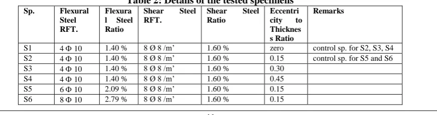
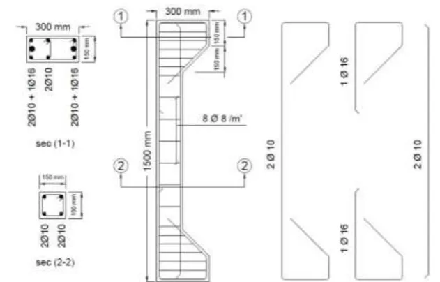
The specimens were divided into two groups. The first group contained four specimens, S1, S2, S3 and S4, were prepared to study the effect of change in eccentricity on column’s behavior. The applied eccentricity to thickness ratio (e/t) varied from zero for the control specimen to 0.15, 0.30 and 0.45. The specimens were reinforced with 410 longitudinal steel reinforcement and 8Ø8 /m’ stirrups reinforcement, with 116 in each end corbel. The second group contained two specimens, S5 and S6, which prepared to study the influence of change of longitudinal steel reinforcement ratio on column’s behaviour. The specimens were reinforced with 610 and 810 longitudinal steel reinforcement respectively, with stirrups reinforcement of 8Ø8 /m’ and 116 in each end corbel. The applied eccentricity to thickness ration on these two specimens was 0.15. The control specimen for this group is S2.The details of the specimens are listed in Table 2. Figures 1-a, 1-b and 1-c showlayouts for the specimens’ reinforcement and dimensions.
Table 2: Details of the tested specimens
Sp. Flexural Steel RFT.
Flexura l Steel Ratio
Shear Steel RFT.
Shear Steel Ratio
Eccentri city to Thicknes s Ratio
Remarks
S1 4 10 1.40 % 8 Ø 8 /m’ 1.60 % zero control sp. for S2, S3, S4
S2 4 10 1.40 % 8 Ø 8 /m’ 1.60 % 0.15 control sp. for S5 and S6
S3 4 10 1.40 % 8 Ø 8 /m’ 1.60 % 0.30
S4 4 10 1.40 % 8 Ø 8 /m’ 1.60 % 0.45
Figure 1-a: Layout of S1, S2, S3 and S4 showing the details of dimensions and reinforcement
Figure 1-b: Layout of S5 showing the details of dimensions and reinforcement
II.III. Instrumentation and testing
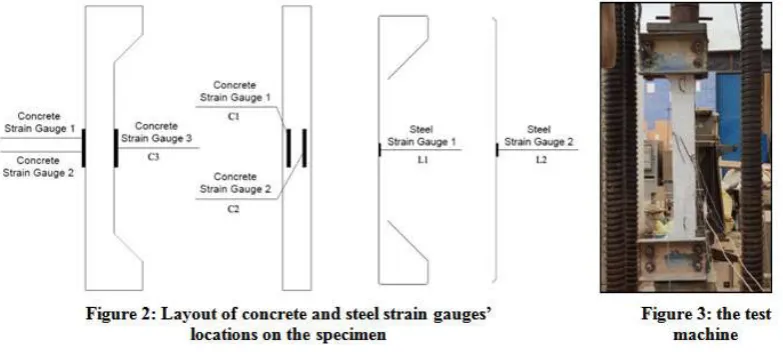
Electrical strain gauges were attached to the specimens to measure the strains of concrete and steel. For steel, two strain gauges were installed on the steel longitudinal bars at their mid height, one of them at the compression side of the column and the other at the tension side. For concrete, three strain gauges were installed on the column’s surface at its mid height, two of them at the tension side of the column and the last one at the compression side. Figure 2 shows a layout for strain gauges locations that installed on specimens.
After three months curing period, the specimens were positioned in the test machine. Two steel caps were used at the ends of the columns to prevent local failure at end corbels. Two hinges were used at both ends of the column at the test machine to prevent end restrictions. The specimens were loaded eccentrically until failure by a hydraulic jack of 5000 kN load capacity. The test machine is shown in Figure 3.
III. EXPERIMENTAL RESULTS AND DISCUSSION
III.I. Summary of the results
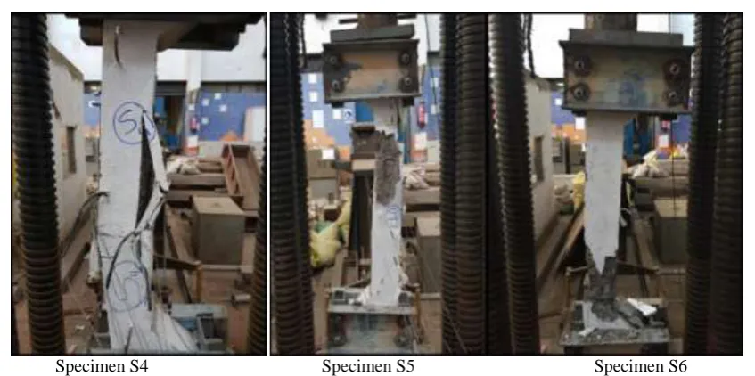
All specimen failed by spalling and crushing of the concrete cover in brittle mode, with large rotation was noticed when the load reached its ultimate value.
Specimens S1, S5 and S6 showed sudden crushes and spalling of the concrete at their failure locations at reaching the peak load. The crush of S1 occurred at all sides of the column, refrain from the appearance of any cracks. While the crush of S5 and S6 occurred at both compression and tension zones, mostly at the compression one, with noticing some horizontal cracks at tension zone before the crushing of the columns.
Specimens S2, S3 and S4 failed by spalling and crushing of the concrete cover at their failure locations in the compression zone of the column at reaching the peak load, with observing horizontal cracks at tension zone of the column at failure location.
S3 showed and early spalling and splitting of its concrete cover. The reason comes back to the confinement weakness at failure location, and the increased thickness of the cover were reasons caused the decrease of the section capacity and thus to the early splitting, giving an odd ultimate load value.
Table 3 lists the test results of the specimens, showing the recorded maximum loads and strains’ values. From the presented values of the recorded strains, it is noteworthy that the longitudinal steel strain did not reach the yield strain (0.002855 mm/mm), proving the brittle failure of the columns. Figure 4-a and 4-b present strain behavior of the tested columns. Failure patterns of all tested specimens are shown in Figure 5.
Table 3: Test results
Specimen Ultimate Load
(kN)
Strain L1* Strain L2* Strain C1,2* Strain C3*
S1 1976 - 0.002250 - 0.00500 - 0.002553 - 0.001300
S2 1184 0.000681 −−−−−** 0.000247 - 0.002170
S3 514 0.000806 - 0.001052 0.001911 - 0.001960
S4 691 0.001063 - 0.000470 0.001274 - 0.001910
S5 1736 0.001880 - 0.001910 0.000891 - 0.002090
S6 1559 −−−−−** - 0.002800 0.000259 - 0.002460
Strain L2: Longitudinal Steel Strain at compression side
Strain C1,2: Concrete Strains 1,2 at tension side (the bigger value)
Strain C3: Concrete Strain at compression side
Figure 4-a: Load versus longitudinal steel strain in tension and compression sides of all specimens
Figure 4-b: Load versus concrete strain in tension and compression sides of all specimens
Specimen S4 Specimen S5 Specimen S6
Figure 5: Failure patterns of the specimens
III.II. Discussion
III.II.I. Effect of eccentricity loading ratio
The variety of load eccentricity has a significant influence on column’s load capacity and failure mode, where the load capacity decreases as the eccentricity increases. The evaluation can be presented by comparing the results of specimens S2, S3 and S4 with their control specimen S1. With increasing the ration of eccentricity to thickness (e/t) by 0.15, specimen S2 load capacity was decreased by 40%. While specimen S3 load capacity was decreased by 74% with increasing e/t by 0.30, taking into consideration the occurrence of local failure, which led to decreasing the section capacity and then the big drop of the load capacity. Specimen S4 load capacity decreased by 65% with increasing e/t by 0.45. Further, the recorded strains indicated that strains increase in tension zone and decrease slightly in compression zone as the eccentricity to thickness ratio increases.
III.II.II. Effect of steel reinforcement ratio
The change of longitudinal reinforcement has a significant influence on column’s load capacity and failure mode, where the load capacity increases as the longitudinal steel reinforcement increases. The behavior can be evaluated by comparing the results of specimens S5 and S6 with their control specimen S2. Increasing the steel reinforcement ratio from 1.40% to 2.09% led to increase in load capacity of the column by 47%. While increasing the steel reinforcement ratio from 1.40% to 2.79% led increase in load capacity of the column by 32%. The reason of the peculiar results of specimens S5 and S6 returns to the prospect of occurring accidental mistakes during mixing, pouring, compacting and curing of the specimens, which affected on specimen S6 compressive strength by decrease. The recorded strains indicated that strains increase as the longitudinal reinforcement ratio increases.
IV. CONCLUSIONS
Based on the presented experimental results, the following conclusions can be drawn:
1- Failure mode of all columns was due to spalling of concrete cover. Columns subjected to eccentric load failed by concrete crushing in compression zone accompanied by horizontal cracks in tension zone. 2- Increasing the eccentricity to thickness ratio (e/t) ratio led to decreasing the ultimate load capacity of the
columns. Increasing the eccentricity to thickness ratio from zero to 0.45 resulted in decreasing column load capacity by 65%.
3- Increasing the longitudinal steel reinforcement ratio resulted in increasing the load capacity of columns. Increasing the steel reinforcement from 1.40% to 2.79% led to increase in column capacity by 32% to 47%.
REFERENCES
[1]. J. Li and M.N.S. Hadi, “Behaviour of externally confined high-strength concrete columns under eccentric loading”, Composite Structures 62 (2003) ELSEVER Journal, pp.145–153.
[2]. ErdemCanbay et al., “High-Strength Concrete Columns under Eccentric Load”, Journal of Structural Engineering · July 2006, pp. 1052–1060.
[3]. Enas Ahmed Abd El-Salam Khattab, “PRODUCTION OF ULTRA HIGH STRENGTH CONCRETE USING LOCAL
[4]. Thomas Vincent and TogayOzbakkaloglu,” Influence of concrete strength and confinement method on axial compressive behavior of FRP confined high- and ultra high-strength concrete”, Composites: Part B 50 (2013) ELSEVER Journal, pp.413–428.
[5]. MiladMohammadiHosinieh, “ Behaviour of High Performance Fibre Reinforced Concrete Columns under Axial Loading”, January
2014.
[6]. Hany A. Kottb et al., “Behavior of high strength concrete columns under eccentric loads”, HBRC Journal (2015) 11, pp. 22–34. [7]. Emad E. Etman et al., “Behavior of High Performance Concrete Columns Subjected to Eccentric Load”, March 2017.
[8]. Chung-Chan Hung, “Behavior of slender UHPC columns under eccentric loading”, Engineering Structures 174 (2018) ELSEVER
Journal, pp.701–711.
[9]. Hyun- Oh Shin et al., “Uniaxial behavior of circular ultra-high-performance fiber-reinforced concrete columns confined by spiral reinforcement”, Construction and Building Materials 168 (2018) ELSEVER Journal, pp.379–393.