The Analysis Of Grid Interconnected System At
Distribution Level Using Renewable Energy
Resources
Nibitha N S, Soumya A V
1
Electrical and Electronics Department, Mar Baselios College of Engineering and Technology,Thiruvananthapuram, India; 2
Electrical and Electronics Department, Mar Baselios College of Engineering and Technology,Thiruvananthapuram, India Email:[email protected]
ABSTRACT: There is growing interest in renewable energy around the world. Since most renewable sources are intermittent in nature, it is a challenging task to integrate renewable energy resources into the power grid infrastructure. Distribution systems provide standby service during utility outages and when operated during peak load hours, potentially reduce energy costs. This paper presents a grid interfacing inverter that compensat es power quality problems and it can also interface renewable energy sources with the electric grid. The grid interfacing invert er can effectively be utilized to perform following functions such as transfer of active power harvested from the renewable resources, load reactive power dema nd support, current harmonic compensation at PCC and current unbalance and neutral current compensat ion in case of 3-phase 4-wire system. Hysteresis current control method is used to generate gate pulses. Total Harmonic Distortion of the grid connected system is analysed. The grid interfac e inverter configuration with IGBT is designed and the graphic models of the Grid Interfacing inverter are developed.Total Harmonic Distortion of the grid connected system is analysed and it is reduced using Harmonic Current Extraction Method using SRF theory are done using MATLAB/SIMULINK.
Keywords: Active power filter(APF),Distributed Generation(DG),distribution system, grid interconnection, power quality(PQ), point of common coupling(PCC),hysteresis current control,grid interfacing inverter,renewable energy sources(RES).
1 INTRODUCTION
The energy demand for electric power is increasing day by day. End users and electric utilities are concerned about meeting the growing energy demand. Distributed generation(DG) systems are presented as a suitable form to offer high reliable electrical power supply[1].The concept is particularly interesting when different kinds of energy resources are available such as photovoltaic panels, fuel cells, or speed wind turbines [2],[3].Most part of these resources need power electronic interfaces to make up local ac grids [4],[5].This way inverters are connected to an ac common bus with the aim to share properly the disperse loads connected to the local grid. The integration of Renewable Energy Resources at the distribution level is termed as Distributed Generation (DG).In this grid integration, communication systems are crucial technologies, which enable the accommodation of distributed renewable energy generation and plays an extremely important role in monitoring, operating, and protecting both renewable energy generators and power systems. Maximum amount of energy demand is supplied by the non-renewable sources, but increasing air pollution, global warming concerns, diminishing fossil fuels and their increasing cost have made it look towards renewable energy sources. Among Renewable sources, wind energy generation has been noted as the most rapidly growing technology; being one of the most cost-effective and environmental friendly mean to generate electricity from renewable sources. High penetration of RES causes issues in stability, voltage regulation and power quality of the system. Because of the application of sophisticated and more advanced software and hardware for the control systems the power quality has become one of the most important issues for power electronic engineers. RES is connected to the grid through grid interfacing inverter for power quality improvement. With great advancement in all areas of engineering, particularly, in signal processing, control systems, and power electronics, the load characteristics have changed completely. In addition to this, loads are becoming very sensitive to voltage supplied to them. The loads based on
inverter, all the four objectives can be accomplished either individually or simultaneously. The PQ constraints at the PCC can therefore be strictly maintained within the utility standards without hardware cost.
2
S
YSTEMU
NDERS
TUDY2.1 Topology
In this paper, it is shown that using an adequate control strategy, with a four-leg four wire grid interfacing inverter, it is possible to mitigate disturbances like voltage unbalance. RES may be a DC source or an AC source with rectifier coupled to dc-link. In this paper wind energy is used as a RES, the variable speed wind turbine generate power at variable ac voltage [22]-[24]. Thus the power generated from these renewable sources need to convert in dc before connecting on dc link [9]-[11].The performance of the proposed control approach is validated with the help of system parameters. Active Power Filters are power electronic devices that cancel out unwanted harmonic currents by injecting a compensation current which cancels harmonics in the line current [11]-[13].Shunt active power filters compensate load current harmonics by injecting equal but opposite harmonic compensating current. Generally, three-wire APFs have been conceived using three leg converters. In this paper, it is shown that using an adequate control strategy, even with a three phase three-wire system. The topology of the investigated APF and itsinterconnection with the grid consists of a three phase four wire voltage source inverter. In this type of applications, the VSI operates as a current controlled voltage source. A voltage source inverter is a power electronic device that connected in shunt or parallel to the system. It can generate a sinusoidal voltage with any required magnitude, frequency and phase angle. It also converts the DC voltage across storage device into a set of three phase AC output voltages. It is also capable to generate or absorbs reactive power [25]. If the output voltage of the VSC is greater than AC bus terminal voltage, is said to be in capacitive mode. So, it will compensate the reactive power through AC system. The type of power switch used is an IGBT in anti-parallel with a diode.
2.2 Control Strategy
The controller requires [8] the three-phase grid currents (Ia,Ib,Ic), the three-phase voltage at the PCC (Va,Vb,Vc) and the DC-link voltage (Vdc).The magnitude Im of the same current is obtained by passing the error signal between the DC-link voltage (Vdc) and a reference voltage (Vdc*) through a PI controller. Using this magnitude and phase displacement of 120 and 240 respectively, the reference three-phase grid currents are Ia*,Ib*,Ic*. The hysteresis control, limit bands are set on either side of a signal representing the desired output waveforms. The inverter switches are operated as the generated signals within limits. Hysteresis band PWM is basically an instantaneous feedbackcontrol method of PWM where the actual signal continually tracks the command signal within a hysteresis band. In this controller compares the measured and reference compensating and gives gate signals to inverter [17], [18].
3
HARMONIC
CURRENT
EXTRACTION
3.1 Overall Control Block
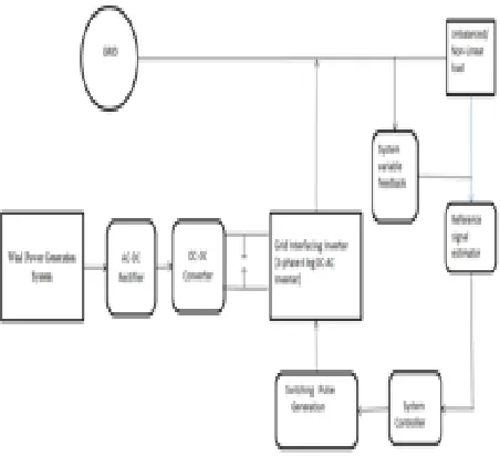
RES is connected to the DC-link of a grid-interfacing Inverter as shown in Fig 1.
.
Fig. 1.Overall Block Diagram Representation.
Fig. 2.Control Strategy Block.
3.2 Modelling of Extraction Block
Fig. 3. Harmonic Extraction Block.
The existence of non-linear loads injects harmonic currents into the distribution lines. Active power filters are used for mitigating the harmonic components. The existing grid-interfacing inverter is used as the shunt active power filter. The working of active filter is based on the principle of injecting the harmonic currents with 1800 phase shift. Hence it requires a suitable controller for the extraction of current harmonics. Here a technique called Synchronous Reference Frame (SRF) theory is used for extracting the harmonics present in the grid currents. This technique has been widely used for most of the recent APFs. The basic SRF method uses the direct and inverse Park’s transformation method, which allows the evaluation of the harmonic components of the input signal. The block diagram representation of the SRF theory for harmonic current extraction is shown in Fig.3. The three phase grid currents are sensed and are passed through a PLL to obtain the grid current frequency, wt (rad/sec). For current harmonic compensation, the distorted grid currents in the a-b-c frame are transferred into two phase rotating referena-b-ce frame using Park’s transformation method, i.e., the a-b-c frame is transferred into d-q-0 frame and Id, Iq, I0 are the corresponding currents. The d-axis current Id is the positive sequence current which is in phase with the voltage, q-axis current Iq is the negative sequence current which is orthogonal to Id and I0 is the zero sequence current. The transformation is done using the cosine and sine functions of the fundamental frequency obtained from the PLL. It helps to maintain the synchronization with the supply voltage. These currents are then passed through a high pass filter (HPF) inorder to separate the harmonics and fundamental frequency components easily. The edge band frequency of the HPF is selected as 50 Hz to eliminate the higher order harmonics. Then these two axis components are transformed back into the three phase components using inverse Park’s transformation method. They represent the harmonic components extracted from the actual grid currents.
4. SIMULATION RESULTS
4.1 Modelling of Grid Interfacing Inverter
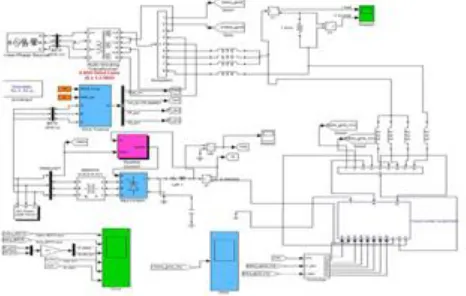
In order to verify the proposed control approach to achieve multi-objectives for grid interfaced DG systems connected to a three-phase four-wire network, an extensive simulation study is carried out using MATLAB/SIMULINK. The Simulink design of distribution system and wind energy system are shown in Fig.4 and Fig.5. A four-leg current controlled voltage source inverter is actively controlled to achieve balanced sinusoidal
grid currents at unity power factor (UPF) despite of highly unbalanced nonlinear load at PCC under varying renewable generating conditions. A Renewable energy source with variable output power is connected on the dc-link of grid-interfacing inverter. An unbalanced three-phase four-wire nonlinear load, whose unbalance, harmonics, and reactive power need to be compensated, is connected on PCC. The waveforms of grid voltage (Va,Vb,Vc), grid currents (Ia,Ib,Ic,) are shown in Fig 6.The output of wind turbine and DC regulator are shown in Fig.7 and Fig.8. Corresponding Switching pulses in Fig.9. Output of Inverter Voltage is shown in Fig.10. Positive values of grid active-reactive powers and inverter active-reactive powers imply that these powers flow from grid side toward PCC and from inverter towards PCC, respectively. The active and reactive powers absorbed by the load are denoted by positive signs. Total Harmonic Distortion (THD) of grid currents for 60 cycles using hysteresis current controller is shown in Fig.11 and it is compensated using Harmonic Current Extraction Method which is shown in Fig.12.
Fig. 4 Distribution System Model
4.2 Modelling of Wind Distribution System
Fig. 6. Waveforms of Grid Voltage and Grid Current.
Fig .7. Wind Turbine Output.
Fig .8.Output Voltage of DC Regulator.
Fig 9. Gate Signals to Inverter.
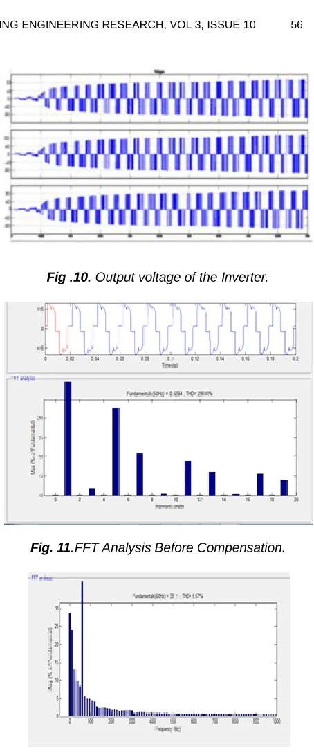
Fig .10. Output voltage of the Inverter.
Fig. 11.FFT Analysis Before Compensation.
Fig. 12. FFT Analysis using Harmonic Extraction Method
Inorder to analyse the distortion,THD analysis is done before and after compensation for the Renewable based Distribution System. A THD comparison is given in Table 1.
TABLE1
THDCOMPARISON
Conventional 29.88%
Harmonic Current Extraction
Method 5.57%
5
C
ONCLUSIONmodelled. Hysteresis current control method is used to generate gate pulses. The inverter is controlled to perform as a multi-function device by incorporating active power filter functionality. The Voltage, Current and Power flow waveforms are obtained. Reactive power demand of the grid is compensated and current harmonics are reduced. It has been found that the total harmonic distortion of grid and load current are reduced and setting of the system is improved. Hence, hysteresis current controller has fast response, high accuracy of tracking the DC-voltage reference, and strong robustness to load sudden variations. Total Harmonic Distortion of the grid connected system is analysed and it is reduced using Harmonic Current Extraction Method from 29.88% to 5.57% using SRF theory are done using MATLAB/SIMULINK.
R
EFERENCES[1] R. H. Lasseter et al., “White paper on integration of distributed energy resources. The CERTS microgrid concept,” in Consort.Electric Reliability.
[2] K. Ro and S. Rahman, “Two-loop controller for maximizing performance of a grid-connected photovoltaic-fuel cell hybrid power plant,” IEEE Trans. Energy Conv., vol. EC-13, pp. 276–281, Sept. 1998.
[3] R. H. Lasseter and P. Piagi, “Providing premium power through distributed resources,” in Proc. IEEE 33rd Hawaii Int. Conf. System Sciences (HICSS’00), 2000, pp. 1–9.
[4] S. R. Wall, “Performance of inverter interfaced distributed generation,” in Proc. IEEE/PES-Transmission and Distribution Conf. Expo., 2001, pp. 945–950.
[5] C. Wekesa and T. Ohnishi, “Utility interactive AC module photovoltaic system with frequency tracking and active power filter capabilities,”in Proc.IEEE-PCC’02 Conf., 2002, pp.316-321.
[6] A.Arulampalam, M.Barnes, A.Engler, “Control of power electronics iinterfaces in distributed generation micro grids" IJE, vol.5, 2004, page no.1-21. [7]. IonelVECHIU, GeluGURGUIATU, Emil ROSU,"Advanced Active Power Conditioner to Improve Power Quality in Microgrids" IPEC.IEEE Conf., 2010. [8]. F. Blaabjerg, R. Teodorescu, M. Liserre, and A. V. Timbus, “Overview of control and grid synchronization for distributed power generation systems,” IEEE Trans. Ind. Electron., vol. 53, no. 5, pp 1398–1409, Oct. 2006.
[7] J. M. Carrasco, L. G. Franquelo, J. T. Bialasiewicz, E. Galván, R. C.P. Guisado, M. Á. M. Prats, J. I. León, and N. M. Alfonso, Power- electronic systems for the grid integration of renewable energy sources: A survey,” IEEE Trans. Ind. Electron., vol. 53, no. 4, pp.1002–1016, Aug. 2006.
[8] B. Renders, K. De Gusseme, W. R. Ryckaert, K. Stockman, L. Van- develde, and M. H. J. Bollen, “Distributed generation for mitigating voltage dips in low-voltage distribution grids,” IEEE Trans. Power.
Del., vol. 23, no. 3, pp. 1581–1588, Jul. 2008.
[9] L.Gyugyi and E.Strycula, “Active AC power filters,” in Conference Rec.IEEE-IAS Annual Meeting, 1976, pp. 529–535.
[10]C. A. Quinn and N. Mohan, “Active filtering of harmonic currents in three-phase, four-wire systems with three-phase, single-phase nonlinear loads,” in Proceedings of IEEE APEC’92, 1992, pp. 829–836.
[11]M.Aredes, E.H.Watanabae, “New Control Algorithms for Series and Shunt Three-Phase 4 Wire Shunt Active Power Filter”, CDROM Proceedings of the ICHQP 2006-International Conference on Harmonics and Quality of Power, Cascais, Portugal, 1-5 October 2006.
[12]K-L.Areerak and K-N.Areerak, “The Comparison Study of Harmonic Detection Methods for Shunt Active Power Filters”, World Academy of Science, Engineering and Technology, Vol:4, 2010-10-23.
[13]Erwin Normanyo, “Mitigation of Harmonics in a Three-Phase, Four-Wire Distribution System using a System of Shunt Passive Filters”, International Journal of Engineering and Technology, Volume 2 No. 5, May, 2012.
[14]Joao afousonMauriaoAredes, Edson Watanabe and Julion Martins, “Shunt Active Filter for Power Quality Improvement”, International Conference UIE 2000 – Electricity for sustainable Urban Development, Lisboa,Portugal , 1-4 Nov 2000.
[15]M. Aziz, Vinod Kumar, AashaChauhan, Bharti Thakur, “Power Quality Improvement by Suppression of Current Harmonics Using Hysteresis Controller Technique”, International Journal of Recent Technology and Engineering (IJRTE) ISSN: 2277-3878, Volume-2, Issue-2, May 2013.
[16]M. Aziz, Vinod Kumar, AashaChauhan, BhartiThakur,“Power Quality Improvement by Suppression of Current Harmonics Using Hysteresis Controller Technique”, International Journal of Recent Technology and Engineering (IJRTE) ISSN: 2277-3878, Volume-2, Issue-2, May 2012.
[17]Marian P. Kazmierkowski, Luigi Malesani, “Current Control Techniques for Three-PhaseVoltage-Source PWM Converters:ASurvey”, IEEE Transactions on Industrial Electronics, October 1998. pp. Vol. 45, No.5.
[18]E. Rokrok and M. E. HamedaniGolshan, “Comprehensive Control Scheme
[20]Md. EnamulHaque, Michael Negnevitsky, and Kashem M. Muttaqi, “A Novel Control Strategy for a Variable-Speed Wind Turbine With a Permanent-Magnet Synchronous Generator”, IEEE Transactions On Industry Applications, Vol. 46, No. 1, pp.331-339, January/February 2010.
[21]D. Dragomi, N.Golonav, P.Postolache, C.Toader, “The Connection to the grid of wind turbines”, IEEE Bucharest Power Tech Conference, June 28-July 2, Bucharest, Romania.
[22]Alejandro Rolan, Alvaro Luna and Gustavo Azevedo, “Modelling of Variable Speed Wind Turbine with a Permanent Magnet Synchronous Generator”, IEEE International Symbosium on Industrial Electronics (ISIS 2009), Seoul Olympic Parktel, Seoul, Korea, July 5-8, 2009.
[23]Ming Yin, Gengyin Li, Chengyong Zhao, “Modeling of the Wind Turbine with a Permanent Magnet Synchronous Generator for Integration”.