YELLOW AND ALL-RED INTERVALS: HOW TO IMPROVE SAFETY
AND REDUCE DELAY?
Faisal Awadallah1
1 Department of Civil Engineering, Birzeit University, Birzeit, Palestine
Received 7 January 2013; accepted 9 April 2013
Abstract:Yellow and all-red intervals are intended as a margin of safety. The duration of change intervals needed for safe stopping or crossing of vehicles is not the same for all traffic conditions and patterns. Thus some traffic patterns may not need the full designed intervals’ durations as a safety margin; while at other times, they are not sufficient due mainly to drivers trying to avoid to stop at red lights. The challenge for traffic engineers is to minimize the intersection delay and at the same time maximize intersection safety. A methodology for providing variable length yellow and all-red intervals, based on traffic responsive sensors and logical commands, is outlined. The methodology stresses that safety is improved at some cases over the designed fixed yellow and all-red intervals, but never compromised lower than the default fixed yellow and all-red intervals. In addition, delay is reduced for various traffic patterns. Adhering to traffic agencies standards and regulations is addressed, not only to outline the practical limitations, but also to introduce discussion for potential positive changes.
Keywords: traffic control devices, traffic safety, traffic signals, traffic delay.
1 Corresponding author: fia@birzeit.edu
1. Introduction
Intersections’ signals provide temporal assignment of right-of-way, thus providing a smooth traffic flow. Change (yellow) intervals are the most troublesome to motorists and most challenging to traffic engineers.
A permissive yellow law indicates that a driver can enter the intersection during the entire yellow interval (Uniform Vehicle Code, 1992). About half the states in the U.S.A. use the permissive yellow law, while the other states mostly use a traffic rule that “vehicles can neither enter the intersection nor be in the intersection on red” or ”vehicles must stop upon receiving the yellow indication, unless it is not possible to do so safely” (Parsonson, 1992).
All-red is that portion of a traffic signal cycle where all approaches have a red-signal display. Some cities and counties in the U.S., as well as, many cities and localities throughout the world do not use the all-red interval. Hence, the intent would be for vehicles to clear the intersection during the yellow interval. However, in such a case a vehicle entering an intersection just before the start of the red interval is bound to be within the intersection on the onset of green interval for the opposing traffic flow. Supplying an all-red interval allows a vehicle that entered the intersection just before the start of the red interval to traverse the intersection before conflict arises with the opposing traffic flow.
length yellow and all-red intervals. The entire all-red interval is not needed at some cases nor is portions of the yellow interval, but in other cases the all-red interval needs to be extended to avoid potential accidents. Detectors for presence and speed at set locations along with logical commands are used to provide variable length yellow and all-red intervals. The general methodology demonstrates how safety is improved in certain cases, but never compromised to be less safe than the design (default) yellow and all-red intervals.
The Manual on Uniform Traffic Control Devices (MUTCD, 2009) stipulates that “the duration of a yellow change interval shall not vary on a cycle-by-cycle basis within the same signal timing plan”; in addition “the duration of a red clearance interval shall not be decreased or omitted on a cycle-by-cycle basis with the same signal timing plan, but it may be extended from its predetermined value for a given cycle based upon the detection of a vehicle that is predicted to violate the red signal indication.” These are very clear instructions. However, the essence of research is to invoke positive changes in policies and regulations. The MUTCD (2009) further states, “The exclusive function of the yellow change interval shall be to warn traffic of an impending change in the right-of-way assignment.” The intent of this research is to secure this function and for some cases improve it; while at other times limiting its associated delay without negatively affecting safety. The paper also addresses the practical implementation aspects of this research; basically using what is allowed according to the MUTCD (2009) regulations and monitoring the other suggested applications.
2. Background
In 2009, there were 33,808 fatalities in the U.S.A. roadways. Of these, 7,043 (20.8%
of total fatalities) were intersection or intersection related (FHWA, 2010). Bonneson et al. (2002) concluded that heavy vehicle drivers are twice as likely to run red lights, as are passenger car drivers; hence contributing to more severe accidents.
The MUTCD (2009) states that “a yellow change interval should have a minimum duration of 3 seconds and a maximum duration of 6 seconds, and the longer intervals should be reserved for use on approaches with higher speeds.” The intent of increasing yellow intervals is to reduce accidents; this is reflected in an FHWA/ITE report (2003), which states lengthening the yellow interval may reduce signal violations. However, Parsonson (1984) demonstrates that the percentage of red-light running increased as yellow durations went from 3 to 5 seconds. Nevertheless, long yellow intervals undoubtedly decrease capacity of intersections and increase the delay to motorists and pedestrians.
The MUTCD (2009) stipulate that the all-red clearance interval is optional, and the duration of the all-red interval shall be predetermined, but should not exceed 6 seconds, except for clearing an exceptionally wide intersection.
3. Traffic Responsive Controls
Most research that intends to improve safety or/and address signal delay concentrated on varying the green interval. Van Katwijk (2008) has addressed usage of traffic responsive control that varies green as well as yellow and all-red intervals. He stressed that compromises are often made between workability and optimality in signal timing control algorithms mainly to vary the duration of green for the various phases. Limiting the indecision of drivers on the onset of the yellow interval for high-speed approaches has been addressed by numerous researches, particularly the extension of green interval until a sufficient gap of traffic occurs or until a maximum green time extension.
McCoy and Pesti (2003) noted that the two most common methods of providing dilemma zone protection on high-speed approaches to signalized intersections are advance warning flashers (AWF) and advance detection (AD). The AWF are active warning signs, usually with yellow flashing beacons designed to operate at a predetermined time before the end of the green interval based on the design speed and the distance from the stop line. The intention of AWF is to reduce the indecision of drivers and providing them with information to encourage them to stop before the stop line. Thus, to create a safe gap when a natural gap out did not occur.
Evaluations of accident experience at AWF signals by Gibby (1992), Klugman et al. (1992), and Sayed et al. (1999) were inconclusive in determining their effectiveness. In the case of AD, detectors are placed on the intended intersection approach to extend the green and prevent the onset of yellow while approaching vehicles are in their dilemma zone. The termination of green is
based on the detectors receiving a sufficient pre-determined gap (gap-out), or the green interval reaching a maximum set time when the delays for the other approaches are no longer acceptable (max-out). Gibby et al. (1992) and Wu et al. (1982) have indicated that AD is effective in reducing crashes on high-speed approaches to signalized intersections, while Parsonson (1992) and Bonneson and McCoy (1994) indicated the loss of dilemma zone protection when the “max-out” occurs.
Tarko et al. (2006) analyzed the probabilistic nature of the Type I dilemma occurrence (a vehicle too close to stop and too far to proceed safely). A property of the likelihood function was noted and used to devise an efficient search algorithm for the optimal green extension. It is based on the positions of all vehicles on the approaches, the vehicle types, the speeds, and the pavement conditions.
immediately. The conclusion of the study showed improvement of this method over the tradition dilemma zone protection methods.
Schattler et al. (2003) evaluated the effect of introducing all-red intervals on red-light running and late entry vehicles. A before and after study at three intersections in Michigan had mixed results; where one intersection had some reduction of red-light violations and the other two intersections showed no significant differences of the before and after studies.
Li and Abbas (2010) used a Monte Carlo simulation framework to present a dilemma hazard model for vehicles in the dilemma zone. The model was used to obtain optimal clearance interval for the study site. Hence, most studies that attempted to address the dilemma zone situation opted for the green interval extension, while other research tried to optimize the duration of the designed clearance interval.
4. Yellow and All-Red Interval Design
Concepts
The ITE’s Traffic Safety Toolbox (1999) defines the “dilemma zone” to be the area in which it may be difficult for a driver to decide whether to stop or proceed through an intersection at the onset of the yellow signal indication. McCoy and Pesti (2002) also refer to it as the “option zone” or the “zone of indecision.” However, Roess et al. (2011) defines the dilemma zone as the distance from the stop line where a driver is too close to stop safely before the conflicting flow is released, and far enough from the stop line that the driver does not have enough time to safely cross the intersection before the conflicting flow is released. For the following analysis, the last definition of dilemma zone is used. The dilemma zone is a function of vehicle speed at the onset of yellow
interval, deceleration rate, vehicle’s length and intersection geometry, especially width of crossing; in addition to drivers’ reaction time, which is based on many factors including drivers’ age, attitude, and their perception of safety. Probabilistic estimation of drivers opting to stop or proceed within a dilemma zone based on differences in perceptions was modeled by Sheffi and Mahmassani (1981). Sharma et al. (2011) stated that the dilemma hazard is a case sensitive function that also depends on geometric conditions, mode of transportation, weather conditions, time of the day and driver’s aggressiveness. A study by Liu et al. (2012) has concluded that the speed of a vehicle approaching the intersection in comparison to the average flow speed of traffic seems to be the best indicator for identifying the aggressive level of a driver. This research recognizes drivers’ perceptions and aggressiveness, especially by realizing their intention to stop or proceed based on comparison of vehicles’ speeds between two sets of detectors, as would be addressed in the next sections. The MTSD (1998) non-dilemma change period (CP, yellow and all-red) is reproduced here in the format of Eq. (1).
(1)
Where tr is the perception-reaction time, V
the design speed, ‘a’ the deceleration rate, W
the width of intersection, and L the length of vehicle (compatible units may be used). It is recommended that the design speed should be set to the speed limit or the approach speed, whichever is higher, to legally defend the signal timing design. Usually the first two terms in Eq. (1) are set for the yellow interval and the last term for the all-red interval. The default values of ‘a’, tr and L are usually 3.3 m/
s2, 1.0 s, and 6.0 m respectively. The equations
before the stop line (S1) and the maximum
distance required to proceed safely to cross the intersection before the conflicting flow is released (S2) are derived from the basic
equations of motion and outlined below:
a
V
V
t
S
r2
21
=
+
(2))
(
2
t
V
t
V
W
L
S
=
r+
c−
+
(3)All terms have been defined earlier with the exception of tc, time at constant speed
following the perception-reaction time, which is needed for a vehicle to clear the intersection, and the units are compatible. The perception-reaction distance term (trV)
is the distanced travelled before applying the brakes as in Eq. (2) or before deciding to continue to travel at constant speed as in Eq. (3). Awadallah (2009) explains three cases regarding S1 and S2: First if S2 < S1 then there
would be a dilemma zone, where vehicles can neither physically stop nor safely proceed. This is not allowed by any design standards.
The second case, S1 equals S2. The ITE’s
MTSD (1998), which is widely used in practice, specifically provides a change interval (yellow + all-red) for a non-dilemma zone as provided in Eq. (1). Thus Eq. (1) is derived by equating S1 to S2 and solving for tc,
which is the last two terms of Eq. (1). Hence, by adding the perception-reaction time (tr)
to the constant speed time (tc), the
non-dilemma change period Eq. (1) is formed. This method provides a decision line, when at the onset of the yellow interval vehicles located before the decision line should decelerate to a stop just before the stop line and vehicles located after the decision line (nearer to the intersection) should proceed at design speed to cross the intersection. This
particularly applies for the design speed and the default values outlined earlier.
The third case, if S2 > S1 then there would
be an option zone (OZ) or a decision zone is formed. Vehicles positioned within the option zone at the onset of the yellow interval have the option to stop safely before the stop line or proceed at the design speed to cross the intersection before the release of the conflicting movement. Furthermore, vehicles positioned before the option zone at the onset of the yellow interval should decelerate to stop before the stop line; while vehicles positioned after the option zone should proceed at the design speed to cross the intersection before the release of the conflicting flow.
The above three equations did not include the effect of approach grade, in order to simplify the analysis; however, the change interval equation that includes the effect of grade is given in Eq. (4):
(4)
All terms have been defined earlier, with the exception of g, the gravitational constant, and
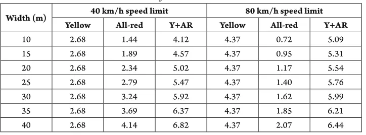
G, grade in decimal form, which should include the positive sign for upgrade and negative sign for downgrade (any compatible units may be used). It is evident from the calculations in Table 1 that yellow and all-red intervals exceed the maximum recommend duration of 6.0 seconds for wide or off-set intersections, such as diamond interchange signals on a main road. The values could be substantially higher for down grade approaches, for truck lengths, and if the 85th percentile speed
for yellow intervals and the 15th percentile
that substantial lost time is incurred for wide signalized intersections; and due to the high delay anticipated by drivers, some of them try to avoid stopping during the yellow change interval. Thus long yellow and all-red intervals not only contribute to intersection delay and reduced capacity; but also could reduce safety at many situations. This is particularly true when drivers try to use yellow and all-red intervals to their limit and hence, they would comprise safety.
Even though the non-dilemma change period provides a decision line for vehicles driving at the design speed and for set default parameters; each vehicle has its own dilemma or option zone. The formation and length of the dilemma or option zone is a function of a vehicle’s speed, length, deceleration rate, and driver’s reaction time. Table 2 shows the calculations for S1 and S2 (as defined
above) for various vehicles’ speeds above and below the design speed of 80 km/h. The calculations are for an intersection width of 15 meters and set default values (outlined in the table’s footnotes). These default values were maintained for both the calculations of the change period and for the different vehicles’ speeds in calculating S1 and S2. Thus vehicles
driving above the design speed would have a dilemma zone, which becomes larger as the speed of vehicles increase. But vehicles driving lower than the design speed would have an option zone; except for vehicles driving at very low speeds. Very slow moving vehicles would have a short dilemma zone just before the stop line. This is not a critical case; a very slow moving vehicle faced with the onset of yellow few meters from the stop line, usually it is able to stop before stop line. But if it enters the intersection at a low speed; it will not be able to clear the intersection before the onset of green for the opposing flow. However, such a vehicle will be clearly visible by drivers that
are about to receive the green interval, and thus accidents would be highly unlikely.
The critical case is for the dilemma zones of speeding vehicles. But such vehicles are in violation of the traffic law. Also if the driver of such vehicle would have a reaction time less than the design one, and/or uses a deceleration rate higher than what was used in calculating the change interval; the dilemma zone could be changed to option zone (with a different length). For example, for the cases in Table 2, if the reaction time of a specific driver would be reduced to 0.8 seconds, and the deceleration rate would be increased to 5.0 m/s2 then for speeds of up to 143 km/h,
the dilemma zones would change to option zones. But for a speed of 144 km/h and more the dilemma zone continues to exist.
5. Yellow and All-Red Variable Length
Intervals
The intent of variable yellow and all-red length intervals is to improve the obedience of drivers for yellow and red signal display. Particularly to reduce intersection crossing at a very late stage of the yellow interval and certainly not to enter the intersection during the red interval. Many drivers that realize the existing of an all-red interval try to use it, or even misuse it. High speed approaches are the most tempting for reckless drives to try to avoid stopping at the stop-line on the onset of yellow intervals, particularly because of the high speed (loss time for deceleration and acceleration) and long yellow durations. High-speed approach accidents are most severe.
duration to other signals. Hence when a vehicle is sufficiently far from the stop-line and the signal head indication turns yellow, thus if a driver decelerates and stops while the yellow interval seems sufficiently long; s/he would realize it may be possible next time to go through. However, if the yellow interval is short then s/he would realize his/her decision was appropriate. In addition, if a driver is taking a risk by proceeding when the designed yellow and all-red interval are not sufficient, extra all-red time may be added up to a set limit to avert an accident. But s/he would realize this was done by crossing a red light and it was a close call that should be avoided in the future. Hence, variable yellow and all-red intervals would increase signal obedience, improve intersection safety; and reduce delay, especially for minor street vehicles. Specific values for such improvements vary according to intersection design and traffic conditions, and could only be determined via actual field studies or simulation techniques that could be validated by pilot field studies.
Variable length yellow and all-red intervals does not conflict with signal semi-actuated control, full-actuated control, or the common “dilemma zone” protection method. It
complements them. Given the change period (yellow and all-red) is designed via the ITE non-dilemma method of Eq. (1); then the location of the decision line may be set via calculation of S1 by Eq. (2). The
decision line is the line where approaching vehicles, positioned before this line, on the onset of yellow interval should stop before or at the stop-line; and vehicles positioned after this line can proceed safely to cross the intersection at the onset of the yellow interval, provided vehicles are travelling at the speed limit. The installation of traffic sensors would provide speed and presence data for each vehicle and this information is used to calculate the variable yellow and all-red intervals. Hence the logical commands could provide viable and valuable options that improves safety and reduces delay for various traffic situations.
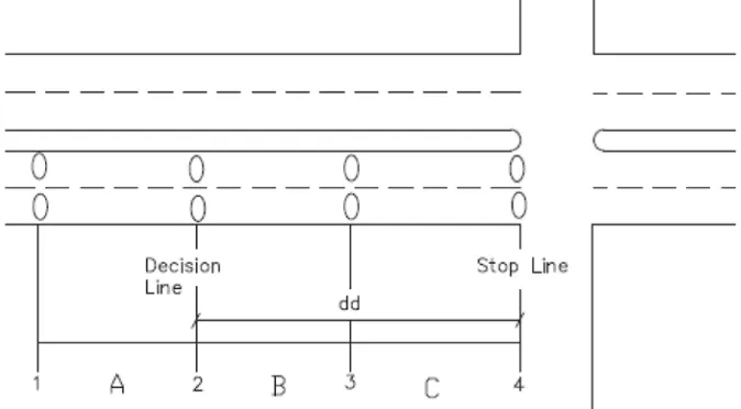
Defining the distance between the decision line and the stop line as the decision distance (dd); it is proposed to have four sets of detectors at the stop line, at the decision line, midpoint between the stop line and decision line, and half the decision distance (1/2 dd) extrapolated upstream from the decision line (Fig. 1). Mirror image of detectors on the other approaching side
Table 1
Yellow and All-Red Interval Calculations for Various Intersection Widths*
Width (m) 40 km/h speed limit 80 km/h speed limit Yellow All-red Y+AR Yellow All-red Y+AR
10 2.68 1.44 4.12 4.37 0.72 5.09
15 2.68 1.89 4.57 4.37 0.95 5.31
20 2.68 2.34 5.02 4.37 1.17 5.54
25 2.68 2.79 5.47 4.37 1.40 5.76
30 2.68 3.24 5.92 4.37 1.62 5.99
35 2.68 3.69 6.37 4.37 1.85 6.21
40 2.68 4.14 6.82 4.37 2.07 6.44
of the main road should also be installed. The proposed traffic detectors are Inductive Loop Detectors (ILD). ILD are a mature technology that is capable of detecting vehicles’ presence and speed with high accuracy; the suggested locations of ILD’s are demonstrated in Fig. 1. Video Image Processing (VIP) detection is a developing technology with many capabilities, which may be used for this type of intersection control with virtual detection lines. It is also possible to directly provide presence per section, which is very useful and not possible directly via ILD. VIP compared to various other detection technologies has showed it has versatility and potential, but it is not recommended for this research due to its high cost and not providing accurate information at some particular traffic and weather conditions (Awadallah 2002; Rhodes et al. 2007). The information provided by ILD coupled with real time calculations, logical commands, and control can be powerful and effective in reducing intersection delays and improving safety.
A main component for the variable yellow and all-red procedure is the determination of vehicles present at a segment (e.g., A, B, or C in Fig. 1) at a set time, such as the onset of the yellow interval. At such a time, the time of the last vehicle passing each set of detectors is noted (time relative to the set reference time), as well as the speed of each of these vehicles. Thus if the time difference between the passing of the last vehicle of a detector set and the set time (e.g., the onset of yellow) is equal to or greater than (≥) the duration needed for such a vehicle to traverse the next section; then no vehicle is present at the section downstream from this detectors’ set. The duration for traversing a section between two detector sets should be calculated for the actual vehicle speed minus 15 km/h, or half the actual vehicle’s speed, whichever is higher. An exceptional case if a vehicle reduces its speed beyond 15 km in this very short time; then it certainly intends to stop and not to proceed. Also, if a parked
Table 2
Formation of a Vehicle Dilemma Zone, Option Zone or Decision Line for Given Speeds at Onset of the Yellow Intervala
Indicators Vehicles’ speed (km/h)
20 40 60 70 80 90 100 120
S1 (m) 10.2 29.8 58.8 76.7 97.0 119.7 144.7 201.7
S2 (m) 8.5 38.0 67.5 82.3 97.0 111.8 126.6 156.1 Zone
typeb DZ OZ OZ OZ DL DZ DZ DZ
Legend:
S1: Vehicles’ minimum stopping distance (meters)
S2: Vehicles’maximum distance to clear intersection (meters)
a: foran approach Change Period, CP = 5.312 s, based on ITE non-dilemma zone method (Eq. (1)) with the following values; a = 3.3 m/s2, t
vehicle on the shoulder just enters one of the sections without crossing a detector yet; but in such a case the vehicle speed would be very low and will have to stop at the stop-line since the yellow has been initiated. In addition, case IV (below) addresses all vehicles passing detectors’ sets 3 and 4 during yellow and all-red intervals to consider maintaining or extending of the all-red interval.
When the main road green phase need to be terminated; there are three possible traffic conditions: a) the designed yellow and all-red intervals are needed and appropriate for the clearance of vehicles of the intersection or to give vehicles time to stop safely before the stop line, b) there are no traffic approaching the intersection (or traffic is at a sufficient distance from the stop line) that at least part of the yellow or/and all-red intervals is not needed, and c) some speeding vehicles approaching the intersection may not have sufficient yellow and all-red time to clear the intersection before the onset of the opposing traffic of the successive green phase, thus
being at a risk of an accident. There are four recommended cases and corresponding logical commands on the onset of termination of green suggested for this research to reduce vehicles’ delay and improve safety for high-speed approaches. They are outlined as follow:
Case I: No vehicles are present in segments A, B, or C on the onset of the yellow interval (Fig. 1) (for this case and all other cases, both sides of the intersection’s approaches are implied in the analysis, i.e., the phase approaches). In this case the yellow interval is initiated for duration of a pre-set minimum value equal to or greater than the all-red interval. A minimum yellow of 3.0 seconds is suggested to provide sufficient visibility recognition time for drivers and to conform to the MUTCD (2009) minimum yellow standard. Thus allowing vehicles within the intersection to clear it, and allow vehicles approaching detectors’ set 1 to realize the change interval prior to the red interval. Hence for this case, delay is certainly reduced for minor street waiting drivers. The critical situation is a speeding vehicle crosses detectors’ set 1
Fig. 1.
just after the traffic signal turns yellow (for the preset minimum duration). In this case there is no relaxation of safety; such a vehicle should be able to stop at or before the stop line even at a higher speed than the speed limit. Signal timing design (particularly by the ITE method, Eq. (1)) allows vehicles travelling at the speed limit at the onset of the yellow interval and located at the decision line to be able to stop safely at the stop line, provided set reaction time and comfortable deceleration rate. Hence, even if vehicles travel faster than the speed limit; they can stop safely provided using a higher deceleration rate or/ and drivers have a lower perception-reaction time. However for this design, at the onset of yellow the closest vehicle would be half the decision distance (1/2 dd) upstream from the decision line. Thus there would be a significant additional safety margin.
Case II: Vehicles present in segment A or/and B on the onset of yellow interval. In this case the designed (default) yellow and all-red duration is maintained, unless a need to extend all-red interval duration is recommended as in case IV. This case does not provide improvement of delay or safety (unless case IV is evoked).
Case III: No vehicles present at segments A and B, but vehicles are present in segment C on the onset of the yellow interval. Similar to case I, the minimum set yellow is initiated. If no vehicles cross detectors’ sets 1, 2, or 3 since the signal turned yellow and until the end of the minimum yellow time; then the time the last vehicle crossed detectors’ set 3 (time relative to end of the minimum yellow time) and speed would be noted. Subsequently the duration of yellow and all red should be re-calculated based on the detection of the last vehicle passing detectors’ set 3; namely the time it needs to clear the intersection at this
speed. Thus the all-red may be reduced or terminated and also the yellow interval may be reduced up to the pre-set minimum, i.e. yellow may terminate immediately after the last calculation results, if the last vehicle that crossed detector set 3 also crossed detector set 4. However, if a new vehicle crosses any of detectors’ sets 1, 2 or 3 (normally would cross only detectors’ set 1 unless a vehicle comes from the shoulder) between the onset of yellow interval and the minimum yellow set time; then the designed yellow and all-red intervals are maintained. This could be further qualified to revert to the default yellow and all-red intervals if the vehicle crossing detectors’ sets 1, 2, or 3 within the given period has a speed greater than a preset minimum (for each detector set) to differential vehicles planning to proceed from those planning to stop, and including a sufficient safety factor.
set 3 to the stop line (1/2 dd) yields a speed of 53 km/h. Thus at this speed or lower, vehicles crossing detectors’ set 3 (Fig. 1) can stop safely at or before the stop line; these vehicles do not require extension of the all-red interval and the designed yellow and all-red are maintained. Vehicles with speeds above this speed and below the design speed, their intention to stop or proceed is not clear. Thus for this speed range; the design yellow and all-red lengths are also maintained. But all vehicles passing detectors’ set 4 (stop line) during yellow and all-red intervals are considered for the extension of the all-red to a preset maximum. Hence only vehicles at or above the design speed, when passing detectors’ set 3 during the yellow interval, are considered for calculation for extension of all-red. The calculation is based on actual vehicle speed, location, and time present at the detector (especially relative to end of the preset minimum yellow or designed yellow interval). Calculations to extend the all-red duration may be initiated based on vehicles passing detectors’ set 3, but the final calculation should be based on such a vehicle passing detectors’ set 4 at the stop line. Calculations for the extension of the all-red interval should be updated by the passing of another vehicle as long it does not exceed the maximum preset all-red extension.
At heavy demand, vehicles are present at most or all sections and the default yellow and all-red is used. Thus the usefulness of this system is minimal, especially for case I and III; but case IV is always operational. Logical commands to reduce delays for heavy volume intersections are possible, but are not addressed in this research. Cassidy et al. (1996) have simulated vehicle actuation detectors at congested intersections and showed that delays at such approaches could be reduced by more than 30%. The existing
detectors can be used along with detectors on the minor streets to allow the intersection signalization to operate as a semi or fully actuated signal or/and to be used for extension of green for a dilemma zone protection arrangement. This would optimize traffic flow and reduce intersection delays at peak periods. Furthermore, if a detector or more malfunctions; the system should revert to the default yellow and all-red intervals. It is always appropriate to design the electrical circuits to provide information for the operator for any type of malfunction of the signal system.
The power of information (detection parameters) and real time calculations are bound to provide numerous reductions to intersection delay and improvements for safety through series of logical commands and controls of signal’s interval indications. There are numerous options, but the cases outlined above entail high certainty of appropriate and safe control based on the critical cases. The default values are those of ITE or those set by any jurisdiction. They are particularly used to calculate the design (default) yellow and all-red intervals, and the decision line.
6. Conclusion
During a substantial percentage of traffic signal’s operation, all or part of the yellow and all-red intervals are not used or needed. Furthermore, increase of the green interval for the common “dilemma zone” protection does not have any effect on safety improvement when terminated via the “max-out” option, but it increases delay for minor approaches.
The inclusive outlined scenarios demonstrate improvement of safety to accommodate vehicles crossing the red light at high speed. This is would clearly help avoid some severe accidents, but to provide an estimate of such reduction would require long period of before and after implementation accident studies. Furthermore, the scenarios clearly indicate reduction of delay for minor approaches, which are subject to the longer periods of delays (as for minor approach signal timing). Thus, reduction of such delays would not be only welcomed by drivers, but also anticipated, particularly with the high technology advancements.
Extension of all-red would involve drivers entering the intersection when the signal is red. This is a clear and serious traffic violation, and such a driver may be subject to a traffic citation; but more significantly, s/he may be saved from a possible severe accident. The theoretical analysis and recommendations for this research are of practical importance. The advance detection technologies and real time monitoring and calculations allow this methodology of logical commands to provide improvements to both safety and delay. Installation of traffic responsive sensors has a high investment and operational costs; thus this arrangement is only suitable for high-speed isolated signalized intersections that have high severe accident rates. Further research is needed to investigate the economic feasibility.
Acknowledgements
Major parts of this paper were presented at the 90th Annual Meeting of the Transportation Research Board, Washington D.C. January 23-27, 2011.
References
Awadallah, F. 2002. Incident detection: selection of appropriate technologies and methodologies, Road and Transport Research Journal, 11(2): 50-56.
Awadallah, F. 2009. A Legal approach to reduce red-light running crashes, Transportation Research Record: Journal of the Transportation Research Board. DOI: http://dx.doi. org/10.3141/2096-14, 2094: 102-106.
Bonneson, J.; McCoy, P. 1994. Manual of traffic detector design, 1st edition. Civil Engineering Department, University of
Nebraska, Lincoln, Nebraska.
Bonneson, J.; Brewer, M.; Zimmerman, K. 2002. Engineering countermeasures to reduce red light running, FHWA-TX-03/ 4027-2. Federal Highway Administration, U.S. Department of Transportation, Washington, D.C.
Cassidy, M.; Chuang, Y.; Vitale, J. 1996. Reexamining vehicle-actuation strategies at isolated signalized intersections, ASCE Journal of Transportation Engineering. DOI: http://dx.doi.org/10.1061/(ASCE)0733-947X(1996)122:3(235), 122(3): 235-240.
FHWA/ITE. 2003. Making intersections saver: a toolbox of engineering countermeasures to reduce red-light running. An informational report, FHWA, U.S. Department of Transportation. Washington, D.C.
FHWA. 2010. Intersection safety. Available from Internet: <http://safety.fhwa.dot.gov/intersection>.
Transportation Research Record: Journal of the Transportation Research Board, 1376: 45-56.
Klugman, A.; Boje, B.; Belrose, M. 1992. A study of the use and operation of advance warning flashers at signalized intersections, Report MN/RC-93/01. Minnesota Department of Transportation, St. Paul, Minnesota. Li, P.; Abbas, M. 2010. Stochastic dilemma hazard model at high-speed signalized intersections, ASCE Journal of Transportation Engineering. DOI: http://dx.doi.org/10.1061/ (ASCE)TE.1943-5436.0000066, 136(5): 448-456. Liu, Y.; Chang, G.; Yu, J. 2012. Empirical study of driver responses during the yellow signal phase at six Maryland intersections, ASCE Journal of Transportation Engineering. DOI: http://dx.doi.org/10.1061/(ASCE)TE.1943-5436.0000278, 138(1): 31-42.
Manual of Traffic Signal Design. 1998. Institute of Transportation Engineers. Washington, D.C.
Manual on Uniform Traffic Control Devices (MUTCD) for Streets and Highways. 2009. FHWA, Washington, D.C. McCoy, P.; Pesti, G. 2002. Dilemma zone protection with advance detection and active warning signs. In Proceedings of the Annual Meeting of the Institute of Transportation Engineers, Philadelphia, PA.
McCoy, P.; Pesti, G. 2003. Improving dilemma-zone protection of advance detection with advance-warning flashers, Transportation Research Record: Journal of the Transportation Research Board. DOI: http://dx.doi. org/10.3141/1844-02, 1844: 11-17.
Parsonson, P. 1984. NCHRP Synthesis of Highway Practice 114: Management of Traffic Signal Maintenance. Transportation Research Board, National Research Council, Washington, D.C.
Parsonson, P. 1992. NCHRP Synthesis of Highway Practice 172: Signal Timing Improvement Practices. TRB, National Research Council, Washington, D.C.
Rhodes, A.; Smaglik, E.J.; Bullock, D.M.; Sturdevant, J.R. 2007. Operational performance comparisons of video detection systems, Institute of Transportation Engineers (ITE) Annual Meeting, Pittsburg, PA, August 5-7: 2007.
Roess, R.; Prassas, E.; McShane, W. 2011. Traffic engineer, 4th edition. Prentice Hall.
Sayed, T.; Vahidi, H.; Rodriguez, F. 1999. Advance warning flashers: do they improve safety?, Transportation Research Record: Journal of the Transportation Research Board. DOI: http://dx.doi.org/10.3141/1692-05, 1692: 30-38.
Schattler, K.; Datta, T.; Hill, C. 2003. Change and clearance interval design on red-light running and late exits,
Transportation Research Record: Journal of the Transportation Research Board. DOI: http://dx.doi.org/10.3141/1856-21, 1856: 193-201.
Sharma, A.; Bullock, D.; Peeta, S. 2011. Estimating dilemma zone hazard function at high speed isolated intersections, Transportation Research Part C: Emerging Technologies. DOI: http://dx.doi.org/10.1016/j. trc.2010.05.002, 19(3): 400-412.
Sheffi, Y.; Mahmassani, H. 1981. A model of driver behavior at high speed signalized intersection,
Transportation Science. DOI: http://dx.doi.org/10.1287/ trsc.15.1.50, 15(1): 50-61.
Tarko, A.; Li, W.; Laracuente, L. 2006. Probabilistic approach to controlling dilemma occurrence at signalized intersections, Transportation Research Record: Journal of the Transportation Research Board. DOI: http://dx.doi. org/10.3141/1973-09 1973: 55-63.
Van Katwijk, T. 2008. Multi-agent look-ahead traffic-adaptive control, Doctorial dissertation, Technical University of Delft. The Netherlands.
Wu, C-S.; Lee, C.E.; Machemehl, R.B.; Williams, J. 1982. Effects of multiple-point detectors on delay and accidents,
Transportation Research Record: Journal of the Transportation Research Board, 881: 1-9.
Zimmerman, K.; Bonneson, J.A.; Middleton, D.; Abbas, M. 2003. Improved detection and control system for isolated high-speed signalized intersections, Transportation Research Record: Journal of the Transportation Research Board. DOI: http://dx.doi.org/10.3141/1856-23, 1856: 212-219.
I N T E R VA L I Ž U T O G I C R V E N O G
SVETLOSNOG SIGNALA: KAKO POVEĆATI
BEZBEDNOST I SMANJITI VREMENSKE
GUBITKE?
Faisal Awadallah
Sažetak: Intervali žutog i crvenog svetlosnog signala namenjeni su da omoguće dozvoljeni nivo bezbednosti. Dužina trajanja promene intervala koja je potrebna za bezbedno zaustavljanje ili prolaženje vozila nije ista za sve saobraćajne uslove i signalne planove. U tom smislu, pojedini saobraćajni signalni planovi ne zahtevaju maksimalno projektovane dužine intervala kao dozvoljenog nivoa bezbednosti; dok u drugim situacijama, isti nisu dovoljni uglavnom zbog vozača koji pokušavaju da izbegnu zaustavljanje na crvenom svetlu. Izazov za saobraćajne inženjere predstavlja minimiziranje vremenskih gubitaka i istovremeno maksimiziranje nivoa bezbednosti na raskrsnici. U radu je prikazana metodologija koja omogućava promenu dužine intervala žutog i crvenog svetlosnog signala, zasnovana na odgovarajućim saobraćajnim senzorima i logičkim komandama. Primenom metodologije je utvrđeno da je bezbednost u nekim situacijama povećana u odnosu na projektovane fiksne dužine intervala žutog i crvenog svetlosnog signala, ali da nikada nije manja od zadatih fiksnih intervala žutog i crvenog svetlosnog signala. Pored toga, vremenski gubitak je smanjen za različite saobraćajne signalne planove. U radu je razmotreno sprovođenje standarda i propisa u saobraćajnim agencijama, kako bi se dao pregled ograničenja koja se javljaju u praksi, kao i da bi se omogućila i rasprava o potencijalnim pozitivnim promenama.