www.mech-sci.net/8/65/2017/ doi:10.5194/ms-8-65-2017
© Author(s) 2017. CC Attribution 3.0 License.
Design and Modelling of a Cable-Driven Parallel-Series
Hybrid Variable Stiffness Joint Mechanism for Robotics
Cihat Bora Yigit and Pinar Boyraz
Department of Mechanical Engineering, Istanbul Technical University, Inonu Cd. No:65, 34437, Beyoglu, Istanbul, Turkey
Correspondence to:Cihat Bora Yigit ([email protected]) and Pinar Boyraz ([email protected])
Received: 25 November 2016 – Revised: 12 February 2017 – Accepted: 24 February 2017 – Published: 22 March 2017
Abstract. The robotics, particularly the humanoid research field, needs new mechanisms to meet the crite-ria enforced by compliance, workspace requirements, motion profile characteristics and vacrite-riable stiffness using lightweight but robust designs. The mechanism proposed herein is a solution to this problem by a parallel-series hybrid mechanism. The parallel term comes from two cable-driven plates supported by a compression spring in between. Furthermore, there is a two-part concentric shaft, passing through both plates connected by a universal joint. Because of the kinematic constraints of the universal joint, the mechanism can be considered as a serial chain. The mechanism has 4 degrees of freedom (DOF) which are pitch, roll, yaw motions and translational movement inz axis for stiffness adjustment. The kinematic model is obtained to define the workspace. The helical spring is analysed by using Castigliano’s Theorem and the behaviour of bending and compression char-acteristics are presented which are validated by using finite element analysis (FEA). Hence, the dynamic model of the mechanism is derived depending on the spring reaction forces and moments. The motion experiments are performed to validate both kinematic and dynamic models. As a result, the proposed mechanism has a potential use in robotics especially in humanoid robot joints, considering the requirements of this robotic field.
1 Introduction
In recent years, there has been an emergent need in robotics to develop new mechanisms that go beyond the convtional structures, focusing on compliant, lightweight and en-ergy efficient designs. Following this need, increasing num-ber of studies related with non-conventional robot mecha-nism design are reported (Grioli et al., 2015). In addition, large workspace, smooth motion profiles, and new mechan-ical structures with certain redundancies to ease the control applications can be considered as desired properties of such mechanisms. Mizuuchi et al. (2002), Yang et al. (2005), Ham et al. (2009) and Vanderborght et al. (2013) also emphasizes that such joint designs are needed in robotics instead of con-ventional structures.
Most of non-conventional mechanisms are studied in con-tinuum and hyper-redundant robotics and used especially in minimally invasive surgery (MIS) robotics. These structures combine the compliancy and lightweight compact design re-quirements, although they may fall short of controllability
2013). On the other hand, an extra difficulty comes from the compactness requirements. Since the continuum back-bone structures have often small diameter in nature, there is very limited space to fit the actuation units within the mod-ule. Therefore, a cable-driven remote manipulation is pre-ferred with often an antagonist arrangement (Potkonjak et al., 2011). Although, it can be used for a different purpose, a very similar humanoid neck mechanism is proposed in Gao et al. (2012b) and is based on a compression spring and two par-allel plates, driven by four cables. The same research group also studied inverse kinematics of the structure in Gao et al. (2012a); however, it differs from the mechanism proposed in this work since in their mechanism, there is no serial link to restrict the highly complex spring movement. A similar mechanism is introduced in Nori et al. (2007) and a partial kinematic model with control strategy is presented. In order to handle the nonlinear dynamics of continuum robots, the elastic rod dynamic behavior can be taken as a model us-ing Cosserat Theory in Cao and Tucker (2008). The contin-uum robotics literature is diverse in terms of pointing the new directions in mechanism design and a detailed review can be found in Walker (2013). However, there are still alterna-tives to elastic back-bone and continuum structures that may lead to more feasible structures. For example novel 3 DOF fully parallel manipulators with rotational capabilities which is given in Liu et al. (2005) can also be considered as good candidates for especially humanoid neck and joint design. The alternative multi-section designs can be structures such as given in Woehrmann et al. (2013) with effective magnetic actuation and interleaved continuum-rigid manipulators as presented in Conrad et al. (2013). Moreover, a non-compliant but similar structure to the mechanism proposed in this paper, known as 3-SPS mechanism is studied in Alici and Shirin-zadeh (2004) and Kim et al. (2015).
In addition to given studies in continuum robotics and cable-driven robotic mechanisms, robotic joint with vary-ing stiffness/compliance is also required. In the last decade, many inspiring developments occured in this area. In Ham et al. (2009) and Vanderborght et al. (2013), the most impor-tant ones are summarized and classified. Among this classifi-cation, the structure-controlled stiffness in Ham et al. (2009) uses the natural characteristics of the elastic element provid-ing the compliance. The “Jack Sprprovid-ing” mechanism in Hol-lander et al. (2005) controls the number of active coils by using a screw mechanism to adjust the stiffness without us-ing any additional elements in the mechanism ,which simpli-fies the design. The proposed mechanism in this paper can be included in this class since it uses natural mechanical be-haviour of the helical spring under bending and compression effects.
In this study, a cable-driven, compression spring-supported hybrid mechanism is proposed. The advantages of the proposed mechanism are the unique combination of multiple traits of variable compliancy, hybrid parallel-serial structure for better controllability and lightweight design.
The mechanism can be used in robotic joints especially in humanoid design due to its smooth motion profile, its poten-tial in design of a multi-section robot as a module or sec-tion which is individually controllable. The main contribu-tion of this paper is to present a new joint mechanism sign which combines advantages of two different joint de-sign approaches. The first approach, which is given in Nori et al. (2007) and Gao et al. (2012b), is to use compression spring and cable-driven actuation. The most important disad-vantage of these structures is modelling and control difficul-ties. These mechanisms do not have accurate mathematical models as serial manipulators have. In the proposed mecha-nism, the additional shaft and the universal joint constrains the motion, which in turn allows treating it as a serial mech-anism and facilitates calculations of the kinematic and dy-namic modelling which are also presented. Furthermore, the shaft allows transferring yaw motion directly. In the second approach, Yang et al. (2005), Lim et al. (2009, 2012), Alici and Shirinzadeh (2004) and Kim et al. (2015) use the two part shaft and the universal joint however the absence of compres-sion spring results in a stiff structure. On the other hand, pro-posed mechanism shows a compliant behaviour as a result of the additional translation motion and the helical compres-sion spring. Linear helical comprescompres-sion spring provides non-linear stiffness characteristics under combined bending and compression effects. Besides, nonlinear stiffness character-istics is essential for a variable stiffness actuator design and most of the designs make use of complex nonlinear spring mechanisms in Ham et al. (2009) and Vanderborght et al. (2013). Another contribution of this study to design literature on variable stiffness actuators is the simplification of nonlin-ear stiffness mechanism. Therefore, the helical spring can be assumed as nonlinear stiffness mechanism under compres-sion and bending effects. Although it is a commonly used machine element, there exist few studies analysing combined effect of bending and compression on a helical spring. In Leech (1994), shape memory alloy wires are used as actua-tors and two different spring loading scenarios are analysed. First a single-sided load is applied, second a pure bending is analysed. Both solutions are based on Castigliano’s The-orem. In this study, the same theorem is used and the solu-tion is improved numerically with the combinasolu-tion of bend-ing and compression scenario.
2 Description of Cable-Driven Parallel-Series (CDPS) Hybrid Mechanism
The proposed mechanism includes a lower plate and an upper plate which are used to hold the compression spring in con-centric position as shown in Fig. 1. The structure is driven by three cables pulled or set free by three servo motors located underneath the CDPS mechanism. The upper plate is able to perform rotation in two axes providing roll and pitch angles. This configuration is further supported by a concentric shaft with a universal joint in the middle, which passes through the mechanism restricting and defining the bending motion of the compression spring. The concentric shaft is actuated by a fourth motor to provide the movement about zaxis – yaw angle. These four motors are encapsulated in a separate case and can be installed at a far location from the mecha-nism which makes the mechamecha-nism lightweight and remotely-actuated. Despite the fact that the mechanism can be classi-fied as a parallel mechanism because of its main construc-tion properties, it is modelled as a serial mechanism due to serial kinematics imposed by the middle shaft and the univer-sal joint. Therefore, the mechanism is called as CDPS hybrid mechanism.
The mechanism has 4 DOF in total, 3 of them are related with motion and the other one is a translational motion along
zaxis for adjusting the stiffness. Two rotations of upper plate (roll and pitch) are actuated in a cable-driven way, however the motion is constrained by the shaft inside the spring and the universal joint. The restriction in the motion simplifies the kinematic and dynamic calculations. The last DOF of the mechanism is the translational motion of the upper plate alongzaxis and is designed to adjust the stiffness value of the spring which determines the combined stiffness of the mech-anism in pitch and roll axes. Within this study, the control is achieved over stiffness via a structure-dependent way with-out using additional screw mechanism as in Hollander et al. (2005). The yaw motion herein is not inherently compliant, therefore modelling and experiments sections do not include yaw motion in this work and examine other 3 DOF (pitch, roll and translation) . However, when required, the compliant behavior can be induced using a torsional spring at the lower plate.
3 Kinematic Modelling
The upper and lower plates of the CDPS mechanism are con-nected by a shaft with a universal joint. Therefore, excluding the yaw motion, the neck mechanism is essentially consid-ered as a serial manipulator with rotation around two differ-ent axes at the cdiffer-enter of the shaft such as pitch and roll and a translation at the end of the shaft, summing up to 3 DOF. The shaft having the universal joint in the middle of the structure transmits the torque to change the yaw angle while providing a geometric constraint for resolving the spring forces because it determines the bending point. Therefore, in this mechanism
Figure 1.CDPS mechanism and its components, with motors, bear-ings and capstans.
the amount of the compression can be taken into account and be described by distance between the center of the universal joint and the upper plate. The yaw motion of shaft does not affect the upper plate, because it is directly transmitted to the robotic head platform. The pitch and roll (θ,φ) angles of the upper plate are determined by the cable lengths. Therefore, the relative position of the upper plate with reference to the lower plate can be defined by using three generalised coordi-nates (θ,φ,d2). They are included in a vector which is
de-noted asq, noting that the vectors are shown with bold italic characters. The variabled2 represents the distance between
the center of the universal joint and the upper plate. The ge-ometric variables used in deriving the kinematic model are given schematically in Fig. 2.
It is clearly seen in Fig. 3 that the neck mechanism is an RRP structure with 3 DOF, having the variables roll, pitch and translation (θ,φ,d2). The local frames (X1,Y1,Z1) and
(X2,Y2,Z2) intersect and one of them is rotated by angle
π/2 with respect to the other one. The distanced1is constant
since it is structurally fixed.
Having defined the variables of the kinematic model, now one can formulate and solve the forward and inverse kine-matics. In forward kinematics, the cable lengths (l1,l2,l3) or
the motor shaft angles are inputs and the roll, pitch angles and translation of the upper plate (θ,φ,d2) are the outputs.
On the other hand, in inverse kinematics, (θ,φ,d2) are
Figure 2.Neck mechanism with variables, local and global axes, cable lengths, upper and lower plate cable assembly points.
where the cables pass through at the lower plate can define the lower plane (O1,O2,O3), the transformation matrix is
used to definePi according toOi. The translation (Tr1) of
constant length of the lower part of the shaft (d1), the
rota-tions (Rot1) of pitch and roll (θ,φ) and the translation (Tr2)
of the upper plate (d2) are taken into account in order to
ob-tain this transformation. These transformations are given in Eq. (1), all together forming the transformation matrixT03in
Eq. (2).
Tr1=
1 0 0 0 0 1 0 0 0 0 1 d1
0 0 0 1
,
Rot1=
cθ sθ sφ sθ cφ 0
0 cφ −sφ 0
−sφ cθ sφ cθ cφ d1
0 0 0 1
,
Tr2=
1 0 0 0 0 1 0 0 0 0 1 d2
0 0 0 1
(1)
T03=
cθ sθ sφ sθ cφ sθ cφd2
0 cφ −sφ −sφd2
−sφ cθ sφ cθ cφ cθ cφd2+d1
0 0 0 1
(2)
Then, the transformation matrix is used to calculatePi= [Pi,x, Pi,y, Pi,z]TusingOi= [Oi,x, Oi,y, Oi,z]Tvia Eq. (3).
Pi
1
=T03
Oi
1
(3)
Figure 3.Reduced serial kinematic model of neck mechanism with RRP structure (pitch, roll and translation).
In order to relate the cable lengths (l1,l2,l3) with upper
plate position (θ,φ,d2), the definition of the Euclidean
dis-tance betweenOi andPi is used. According to this
defini-tion, any cable length can be defined by the expression given in Eq. (4).
li= q
(Pi,x−Oi,x)2+(Pi,y−Oi,y)2+(Pi,z−Oi,z)2,
where i=1,2,3 (4)
If we could obtain the correctPi coordinates using Oi
from the kinematic solution, the nonlinear error functionfi
defined by Eq. (5) must be zero.
fi=li− q
(Pi,x−Oi,x)2+(Pi,y−Oi,y)2+(Pi,z−Oi,z)2
=0 (5)
Using Eqs. (3) and (5), any variable can be obtained nu-merically using recursive Newton-Raphson algorithm given by Eq. (6).
qk=qk−1−J−1F (6)
whereJis the Jacobian matrix defined by Eq. (7) andqk is thekth iteration of the solution for the vector of the gen-eralised coordinates, while vectorF is formed by equations
J= ∂f1 θ ∂f1 φ ∂f1 d2 ∂f2 θ ∂f2 φ ∂f2 d2 ∂f3 θ ∂f3 φ ∂f3 d2 (7)
The solution of inverse kinematics is straightforward by using Eq. (5) when desired state variables are known. Addi-tionally, a simple kinematic model is included, which mini-mizes the compression of the spring. The model assumes one cable is fixed at the initial position and takes only an orien-tation input. It is indeed possible to realize all the pitch and roll angles by manipulating only two cables. For each cable, a separate solution loop is defined according to the selected non-moving (i.e. idle) cable. The solution proceeds in the ap-propriate direction (i.e. towards minimizing approximation error) for finding the lengths of the remaining cables to re-alize the roll and pitch angles given in the inverse kinematic problem. According to this method, only two selected cables are manipulated at any motion command. This approach is also reflected at the simplified Jacobian matrix used in the inverse kinematic problem as given in Eq. (8).
J= ∂f1 l2 ∂f1 l3 ∂f1 d2 ∂f2 l2 ∂f2 l3 ∂f2 d2 ∂f3 l2 ∂f3 l3 ∂f3 d2 =
0 0 ∂f1 d2
1 0 ∂f2 d2
0 1 ∂f3 d2
(8)
The simplified kinematic model can be better understood by looking at the Fig. 4 where top view of the lower plate is given. The virtual lines between the points ofOi and the
center divides the plate into three areas. Desired pitch and roll motions can be shown as a vector to determine the mov-ing and fixed cables. Two cables neighbourmov-ing the area which includes the motion vector, are pulled to perform the desired motion. Besides, opposite cable length is set to default ini-tial value. For example, to complete a 30◦ rotation in both pitch and roll axes, the distance between upper plate and the lower plate has to be decreased in the direction of vectorE. Thus, the neighbouring cables of this area which includes the vector are cable 1 and 3. The amount of pull or motor shaft rotation for these cables are calculated by using Eqs. (7) and (8). The length of cable 2 is set to default value.
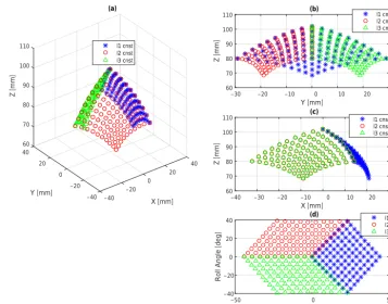
The mechanism is implemented as a humanoid neck plat-form and it is used throughout the study. The same param-eters with the implemented mechanism, which are given in Table 1, are used for workspace simulation. The positions of the midpoint and the orientations of the upper plate are calcu-lated, using simplified forward kinematics, i.e., keeping one cable length constant at default value (95 mm) while chang-ing the other two within 50–95 mm range, as seen in Fig. 5.
The workspace for the simplified kinematic algorithm is given in Fig. 5a. The workspace is obtained as a sum of three distinct cases. In each case, one of the cable is held at 95 mm. The midpoint of the upper plate is shown with dif-ferent colours and symbols for each case. Figure 5b and c
O
1O
2O
3Y
0X
0E
Figure 4.Top view of the lower plate and an example motion com-mand vector.
Table 1.Simulation parameters in workspace analysis.
Variable Value [unit]
Lower shaft lengthd1 47 [mm]
Length of constant cable 95 [mm]
Distance between lower plate center andOipoints 40 [mm]
Distance between upper plate center andPipoints 40 [mm]
showY−ZandX−Zviews of the same figure, respectively. The cable numbers 2 and 3 are placed symmetrically with respect tox axis which results a symmetrical distribution in
40 20
X [mm] 0 –20 –40
(a)
–40 –20 0
Y [mm] 20 60 80 90 100 110
70
40
Z [mm]
l1 cnst l2 cnst l3 cnst
Y [mm]
–30 –20 –10 0 10 20 30
Z [mm]
60 70 80 90 100
110 (b) l1 cnst
l2 cnst l3 cnst
X [mm]
–40 –30 –20 –10 0 10 20 30
Z [mm]
60 70 80 90 100
110 (c) l1 cnst
l2 cnst l3 cnst
Pitch angle [deg]
–50 0 50
Roll Angle [deg]
–40 –20 0 20
40 (d) l1 cnst
l2 cnst l3 cnst
Figure 5.Workspace of the proposed mechanism in(a)3-D,(b)Y−Z,(c)X−Zview,(d)Pitch and Roll Angles.
considered as the motion boundaries when compared to the full ROM of humans. However, it is enough for performing daily activities when the proposed mechanism is used as a humanoid neck joint.
4 Dynamic Modelling
In dynamic modelling, the result of kinematic model (posi-tion, velocity and acceleration) obtained in Sect. 3 is used to define the dynamic motion of the mechanism under cable based forces. The dynamic modelling is composed of three sequential steps: (i) reduction of 3-D model into a 2-D model without information loss, (ii) force analysis on a bending he-lical spring using Castigliano’s Theorem, and (iii) complete dynamic model.
4.1 Dimension Reduction of the Model
To decrease the complexity of computations and its cost dur-ing the analysis of helical sprdur-ing under benddur-ing and com-pression effects, it is possible to reduce the dimension with-out information loss. Deformations of the helical spring can be considered and calculated in a 2-D model because of its cylindrical shape. In order to simplify the computation of bending of helical spring in 3-D coordinates, a different Euler angles convention is used as follows: Two rotations of mechanism aroundX0andY0 axes are defined in Euler
(X−Y−Z) convention and called roll and pitch angles,
re-spectively. However, these two angles can be defined in Eu-ler (Z−X−Y) convention. Thus, theX−Y plane is rotated aroundZ0axis so that bending of the helical spring appears
only in this plane. Then the bending or rotation around new
xaxis is called as deflection angle and denoted withρ.
4.2 Helical Spring Analysis
The helical spring is subjected to bending effects rather than buckling. The cables are assumed to have constant lengths, hence no plastic/elastic deformation are allowed for the ca-bles. The universal joint in the middle determines the bend-ing point of the helical sprbend-ing. Figure 6 shows geometrical relations and frames which are used to calculate the dynamic model of the system.
The framexkykzkis attached to the bottom center all of the
coils. The variablekis the index number of the coils so that
x0y0z0andX0Y0Z0 are coincident on the lower plate.
Suc-cessive coil frames are rotated around theirxaxes in equally so thatzn−1andZ3are tangent. The vectorNkstands for the
origins of all coils.
The same idea is used for helical spring analysis as in Leech (1994) and each coil of the spring is separately anal-ysed. In order to use Castigliano’s Theorem, infinitesimal el-ements are defined in the helical spring. Figure 6 shows the helical spring and the frame definitions. Angular position of the infinitesimal elements onkth coil is defined asαonxkyk
Figure 6. (a)Local frames on spring and infinitesimal element.
(b)Top view of a spring coil.
In order to define strength properties of the infinitesimal element on the spring coils, a 2-D frame is attached to all el-ements. The vectorxis placed on tangential direction and
the vectory is placed on normal direction. This frame and
the other variables which are used to calculate the deforma-tion of the spring are shown in Fig. 6.
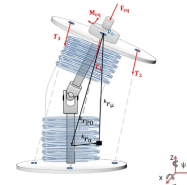
The cable forces are shown in Fig. 7 which are acting on the upper plate are defined asT1,T2andT3. These forces
are unidirectional and are reduced to generalized forces def-inition which includes a force on−zn−1 direction which is
Feqand a moment aroundxn−1axis which isMeq. To
cal-culate the relation between the deformation of the spring and the generalized forces, the distances between upper plate center point and central points of the infinitesimal elements have to be defined. The position vector of the central point of the upper plateP0with respect to framek is represented
askrP0. The position of an infinitesimal element “µ’ onkth
coil of the spring,krµ, is defined as in Eq. (9),
kr
µ=krα+krP0 (9)
where krα is described as the position of the infinitesimal
element in the particular coil and is given in Eq. (10).
kr α=
Rcos(α) Rsin(α) (Nk,z+Nk+1,z
−(Nk,z)α 25
(10)
The moment vector,kMµ, which is resulting from the
equiv-alent force vector and is acting on the elementµis calculated by using cross product given in Eq. (11).
kM
µ=krµ×kFeq (11)
Next, the total moment acting on the element (kMµt) is
cal-culated as given in Eq. (12).
kM
µt=kMµ+kMeq (12)
In order to use the moment in Castigliano’s Formula, it has to be defined in the element specific frame xy. Since the
Figure 7.Spring and cable forces acting on the mechanism.
given moments are defined in coil frame, a rotation is needed asαaboutzk axis, using the rotation matrix (Rotz(α)). The
rotated moment vector (kMc) can be obtained as
kM
c=Rotz(α)kMµt. (13)
Using the Castigliano’s Theorem, bending ((Ub1)k, (Ub2)k)
and torsional ((Ut)k) strain energies are given in Eqs. (14),
(15) and (16), respectively. The material properties which are modulus of elasticity and shear modulus are represented as
EandG. The geometric quantitiesI,J andRare defined as area moment inertia, polar moment inertia and radius of the helical spring.
(Ub1)k= 25 Z
0
(kMc,y)2
2EI Rdα (14)
(Ub2)k= 25 Z
0
(kMc,z)2
2EI Rdα (15)
(Ut)k= 25 Z
0
(kMc,x)2
2GJ Rdα (16)
Summation of three strain energies give full strain energy of a single coil ((U)k) and it is added for every coil to calculate
the total strain energy of the spring (U), which are given in Eqs. (17) and (18), respectively.
(U)k=(Ub1)+(Ub2)+(Ut)k (17)
(U)= n−1
X
k=0
The Castigliano’s Theorem states that derivatives of the strain energies equal to the deformations which are the com-pression distance1d2and the 2-D bending angleρwhich is
projection of pitch and roll angles on 2-D plane.
1d2=
∂(U)
∂Feq
(19)
ρ= ∂(U) ∂Meq
(20)
As a result, the nonlinear force-deformation relation or stiff-ness equation of the spring can be written in given form in Eq. (20).
Feq
Meq
= [K]
1d2
ρ
(21)
The analysis is performed by using the Matlab Symbolic Toolbox for each1d2(between 0◦and 32 mm with 1 mm
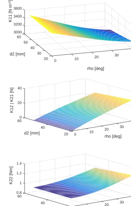
in-crements) andρ(between 0 and 40◦with 1◦increments). The result of 2×2Kmatrices are collected within a look-up table. Wire and spring radii are 1.5 and 16.5 mm, respectively. The number of active coils are 8 and the material of the spring is ASTM A227. In the dynamic model, the algorithm uses the appropriateKmatrix values according to the generalised coordinates. With the definition ofKmatrix as in Eq. (22), theK12 andK21 elements are same due to the symmetrical
structure of the stiffness matrix. The simulation results for
K11,K12andK22elements are given in Fig. 8.
[K]=
K11K12
K21K22
(22)
K11can be interpreted as the relation between the
transla-tional motion of the upper plate1d2and the reaction force
of the spring in the same direction. Since the stiffness matrix is symmetric,K12andK21are equal.K12is the relation
be-tween combined rotationρand reaction force of the spring. Similarly, K21 connects1d2and the reaction moment. The
combined rotation and the reaction moment are connected by
K22. According to the Fig. 8, when both roll and pitch angles
are zero, the translational motion has no effect on the change of the elements of stiffness matrix. Thus, this configuration of the mechanism can be called as a singular position for stiffness. On the other hand, all of the elements of the ma-trix decreases with the increase in the value of 1d2, which
means the spring gets softer with the compression. Compared to other parameters,K11 responds to the change ofρ
differ-ently. The decrease ofK11is obvious with the increasing
val-ues ofρwhile the other parameters increase. So, the bending motion softens the spring for compression effect and it gets stiffer for rotation. Although the stiffness of the mechanism is adjusted with the translational motion of the upper plate, the bending angle has more effect on the stiffness of the mech-anism. As a result of this, the stiffness value depends on the configuration of the mechanism. But, it also changes with the
40 30
rho [deg]
20 10 0
20 30 40 50
d2 [mm]
3000 3200 3400 3600
60
K
1
1
[
N
m
–
1]
40 30
rho [deg]
20 10 0 20 40
d2 [mm]
0 20 40
60
K12 | K21 [N]
40 30
rho [deg]
20 10 0 20 40
d2 [mm]
0.8 1 1.2 1.4
60
K22 [Nm]
Figure 8.Stiffness matrix change with respect to bending angle and compression length.
variation of1d2which gives variable stiffness ability to the
mechanism.
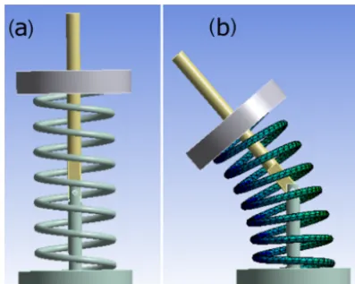
Since finite element analysis (FEA) is commonly used tool for structural mechanics, this technique is used to validate the results of the stiffness analysis proposed in this study. In Fig. 9a and b, initial shape and the deformed shape of the mechanism are shown, respectively. The upper and the lower plates and the shaft are assumed to be rigid parts to isolate spring in analysis particularly and to simplify the model. Ad-ditionally, the spring is fixed to lower and upper plates. A rev-olute joint relation is defined between two shaft parts. Simi-larly, a translational joint constraint is described between the upper plate and the lower part of the shaft. A prescribed mo-tion profile is applied to these relamo-tions as 10 mm translamo-tion and 40◦rotation. As a result, reaction forces and moments of the spring are obtained during the motion.
Figure 9.The models of the mechanism in finite element analysis.
(a)Initial,(b)deformed.
and moments are calculated using FEA and stiffness values which are given in Fig. 8. The mean errors between FEA and the proposed method are 2.2 % for reaction force and 1.5 % for reaction moment. A convergence problem can be seen in the initial steps of FEA method. Moreover, quadratic function behaviour can be seen from both force and moment graphs which is a result of linearly changing stiffness val-ues. Subsequently, the results of FEA demonstrates that lin-ear helical spring shows a nonlinlin-ear behaviour subjected to bending and compression effects.
4.3 Complete Dynamic Model
The equation of motion of a serial manipulator is defined as in Eq. (23).
M(q)q¨+C(q,q)˙ q˙+G(q)=B(q)T +Fs(q) (23)
The vectorqis the generalized coordinates vector[θ, φ, d2]T,
˙
q and q¨ are the velocity and acceleration vectors, respec-tively. M is the mass matrix,Cincludes Coriolis and cen-trifugal forces andGis the gravity matrix. There are no mo-tors connected joints directly. Cable tensions are taken into account with a mapping matrixBwhich is given in Eq. (24). Fsis the generalized force vector of helical spring andsi is
the unit vector on theith cable direction. The variablesPi,x, Pi,y,Pi,zare the positions of connection points of upper plate
and each cable.
B(q)=
" s
1,z s2,z s3,z
−P1,zs1,y+P1ys1,z −P2,zs2,y+P2ys1,z −P2,zs2,y+P2ys2,z P1,zs1,x−P1xs1,z P2,zs2,x−P2xs2,z P2,zs2,x−P2xs2,z
# (24)
5 Experiments and Results
In this section, the implementation of the proposed mech-anism is explained. First, the mechanical construction and
Bending [deg]
0 5 10 15 20 25 30 35 40
Compression [mm]
0 1 2 3 4 5 6 7 8 9 10
Reaction
force [N]
-10 0 10 20 30 40
50 (a)
Proposed method Finite element method
Bending [deg]
0 5 10 15 20 25 30 35 40
Compression [mm]
0 1 2 3 4 5 6 7 8 9 10
Reaction
m
oment [Nmm]
-400 -200 0 200 400 600 800 1000
1200 (b)
Proposed method Finite element method
Figure 10.Behaviour of the spring under compression and bending effects.(a)Reaction force.(b)Reaction moment.
components are introduced. Then control structure, sensors and the software are given. In the experimental results sec-tion, the mechanism performs a controlled motion where the parameters are measured to validate the kinematic and dy-namic models. The implemented mechanism is used as hu-manoid neck in UMAY project (Boyraz et al., 2013).
5.1 Experimental Setup
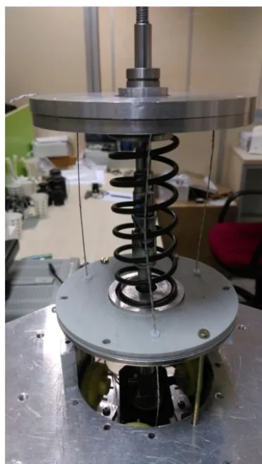
Figure 11.UMAY neck mechanism.
chromed steel (AISI E 52100). Four Robotis Dynamixel MX-28 motors, which has 2.5 Nm stall torque at 12 V, are used. One of the motors are directly connected to shaft in order to perform yaw motion. Other three motors are connected to the cables with 14 mm radius capstans. Fishing lines (with 0.5 mm radius) are used as cable material which have a 100 N payload capacity. The friction force between the lower plate and the cables are reduced using PTFE tubes (with 2 mm in-ner radius) inO1,O2andO3points. A picture of the
imple-mented mechanism is given in Fig. 11 and a video is pre-sented in the Supplement. The video is composed of ran-domly chosen pitch and roll motion combinations. Although the translational motion of the upper plate in zero positions of pitch and roll angles neither affects the stiffness nor the orientation, it is illustrated in the video to emphasize the mo-tion. Three cables are pulled equal amount in length to obtain pure translational motion in the video.
5.2 Results
The experimental setup is equipped with Razor 9 DOF iner-tial measurement unit (IMU) which is attached on the upper plate along the x axis. The IMU is used to collect the
ori-GUI node Cubic trajectorynode trajectory nodeDynamixel
Dynamixel motors CDPS mechanism
IMU
Inverse kinematic server
User input (pitch and roll)
Trajectory for each motor Motor
angles
Pitch roll
Motion of cables
Pitch and roll angles
Motor currents
Figure 12.Control structure used in experiments.
entation data of output shaft in pitch and roll axes. IMU is used to create a truth table to validate the orientation outputs. The only feedback devices are the encoders of Dynamixel motors.
The whole position control structure used in experiments is programmed within Robot Operating System (ROS) which can be seen in Fig. 12. It is worth noting that the con-trol scheme considers only kinematics of the mechanism. A graphical user interface (GUI) node is designed to collect data from the human user. The commands are sent to cu-bic trajectory node which enquires necessary motor angles from inverse kinematic server. Since the aim is to validate the models, the server calculates the necessary motor angle changes with the simplified solution of inverse kinematics as explained in Sect. 3. In this solution, one of the cables are held at a constant position. Therefore, the inverse kinematic server returns with the other cable lengths andd2parameter
while ignoring the stiffness value. The cubic trajectory node takes these arguments as input and calculates a cubic poly-nomial for motor angles. The total trajectory time is given as 2 s for each trajectory which is a feasible amount of time for given workspace and motors. The cubic trajectory of motor shaft angles are sent to Dynamixel trajectory node.
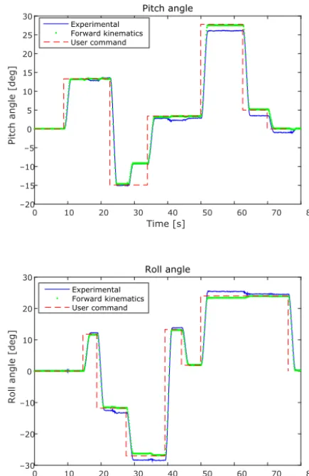
In this section, all given data are obtained from a single one of several experiments. Thus, all figures are connected to each other. The experimental results are given for pitch/roll angles and related motors. The yaw axis motion and dynam-ics are excluded because they do not affect the motion of the upper plate and stiffness. The experiment is performed for 80 s which is long enough for an arbitrary duration to validate random pitch and roll input commands. A user gives random pitch and roll angle commands using GUI which is given in detail in this section. The experimental results are presented in two categories. First, in order to validate kinematic model, orientation of the output shaft and forward kinematics are compared. Second, motor load data and the inverse dynam-ics solution are examined.
Time [s]
0 10 20 30 40 50 60 70 80
Pitch angle [deg]
–20 –15 –10 –5 0 5 10 15 20 25
30 Pitch angle
Experimental Forward kinematics User command
Time [s]
0 10 20 30 40 50 60 70 80
Roll angle [deg]
–30 –20 –10 0 10 20
30 Roll angle
Experimental Forward kinematics User command
Figure 13.Angular positions of the output shaft in pitch and roll axes.
kinematic solutions are calculated using motor shaft angles which are obtained from experiment.
Inverse dynamic algorithm is performed using user com-mands collected from GUI in order to estimate cable ten-sions for each motor. Additionally, the load data is used to estimate cable tensions which is provided by Dynamixel mo-tors and obtained from motor current values. Two cable ten-sion estimations are compared for front cable, left cable and right cable as can be seen in Fig. 14. The general behavior of these data for each motor are similar, but there are errors in some parts of these results because of three reasons. First, the motor current measurements are very noisy due to the use of pulse width modulation of the motor low level con-troller. Second, neglected effects such as friction in gearbox of motor, friction between cable and PTFE parts appears dif-ference between torque estimation from motor current and inverse dynamics model result. Finally, DC motors have no load current which is not taken into account in this estima-tion.
Time [s]
0 20 40 60 80
T1 [N]
–0.2 0 0.2 0.4 0.6 0.8
Motor current Inverse dynamics
Time [s]
0 20 40 60 80
T2 [N]
–0.2 0 0.2 0.4 0.6
Motor current Inverse dynamics
Time [s]
0 20 40 60 80
T3 [N]
–0.2 0 0.2 0.4 0.6 0.8
Motor current Inverse dynamics
Figure 14.Cable tension estimations from inverse dynamics and motor currents.
6 Conclusions
The proposed mechanism is implemented and operated to validate the models given in the paper. Experiments are stud-ied for kinematics and dynamics. In kinematics part, the ori-entation of the output shaft is compared to forward kinemat-ics computations. It is shown that forward kinematkinemat-ics can predict motion profile of the output shaft. In dynamics sec-tion, two estimations of cable tensions, one from motor cur-rent and the other one from inverse dynamics calculations, are examined. It can be seen that, the results from the inverse dynamic calculations are similar to the motor current values. In future work, the closed-loop stiffness control and hy-brid position-force control techniques are going to be ap-plied to the mechanism. With its large workspace, smooth motion profiles, lightweight mechanical structure and vari-able stiffness properties, the possible application area to this mechanism could be humanoid robots. It is indeed used as a humanoid neck mechanism in UMAY project. Humanoid robots interact with their environments and humans. Force interaction with humans requires safe operation conditions. After applying force control techniques, it can be used in hu-manoid joints where the force interaction occurs such as arms and hands in a safe manner as a result of compliant nature of the mechanism.
Data availability. All the data used in this manuscript can be ob-tained by requesting from the corresponding author.
The Supplement related to this article is available online at doi:10.5194/ms-8-65-2017-supplement.
Competing interests. The authors declare that they have no con-flict of interest.
Acknowledgements. The project is supported by Scientific Research Projects Unit of Istanbul Technical University Young Researcher Award.
Edited by: M. Wojtyra
Reviewed by: two anonymous referees
References
Alici, G. and Shirinzadeh, B.: Topology optimisation and singu-larity analysis of a 3-SPS parallel manipulator with a passive constraining spherical joint, Mech. Mach. Theory, 39, 215–235, 2004.
Bennett, S. E., Schenk, R. J., and Simmons, E. D.: Active range of motion utilized in the cervical spine to perform daily functional tasks, Clinical Spine Surgery, 15, 307–311, 2002.
Boyraz, P., Yigit, C. B., and Bicer, H. O.: UMAY 1: A modular hu-manoid platform for education and rehabilitation of children with
autism spectrum disorders, IEEE, 9th Asian Control Conference (ASCC), 1–6, 2013.
Cao, D. and Tucker, R. W.: Nonlinear dynamics of elastic rods us-ing the Cosserat theory: modellus-ing and simulation, Int. J. Solids Struct., 45, 460–477, 2008.
Conrad, B. L., Jung, J., Penning, R. S., and Zinn, M. R.: Inter-leaved continuum-rigid manipulation: An augmented approach for robotic minimally-invasive flexible catheter-based proce-dures, IEEE International Conference on Robotics and Automa-tion (ICRA), 718–724, 2013.
Ferrario, V. F., Sforza, C., Serrao, G., Grassi, G., and Mossi, E.: Active range of motion of the head and cervical spine: a three-dimensional investigation in healthy young adults, J. Orthop. Res., 20, 122–129, 2002.
Gao, B., Xu, J., Zhao, J., and Xi, N.: Combined inverse kinematic and static analysis and optimal design of a cable-driven mecha-nism with a spring spine, Adv. Robotics, 26, 923–946, 2012a. Gao, B., Xu, J., Zhao, J., Xi, N., Shen, Y., and Yang, R.: A humanoid
neck system featuring low motion-noise, J. Intell. Robot. Syst., 67, 101–116, 2012b.
Gravagne, I. A., Rahn, C. D., and Walker, I. D.: Large deflection dynamics and control for planar continuum robots, IEEE/ASME Transactions on Mechatronics, 8, 299–307, 2003.
Grioli, G., Wolf, S., Garabini, M., Catalano, M., Burdet, E., Cald-well, D., Carloni, R., Friedl, W., Grebenstein, M., Laffranchi, M., Lefeber, D., Stramigioli, S., Tsagarakis, N., van Damme, M., Vanderborght, B., Albu-Schaeffer, A., and Bicchi, A.: Variable stiffness actuators: The user’s point of view, Int. J. Robot. Res., 34, 727–743, 2015.
Ham, R. V., Sugar, T. G., Vanderborght, B., Hollander, K. W., and Lefeber, D.: Compliant actuator designs, IEEE Robot. Autom. Mag., 16, 81–94, 2009.
Hollander, K. W., Sugar, T. G., and Herring, D. E.: Adjustable robotic tendon using a “jack spring”, in: Rehabilitation Robotics, IEEE, 9th International Conference on ICORR 2005, 113–118, 2005.
Jones, B. A. and Walker, I. D.: Kinematics for multisection contin-uum robots, IEEE T. Robot., 22, 43–55, 2006.
Kim, J. S., Jeong, J. H., and Park, J. H.: Inverse kinematics and geo-metric singularity analysis of a 3-SPS/S redundant motion mech-anism using conformal geometric algebra, Mech. Mach. Theory, 90, 23–36, 2015.
Leech, A. R.: A study of the deformation of helical springs under eccentric loading, PhD thesis, Naval Postgraduate School, Mon-terey, California, 1994.
Lim, W., Yeo, S., Yang, G., and Mustafa, S.: Kinematic analysis and design optimization of a cable-driven universal joint module, in: Advanced Intelligent Mechatronics, IEEE/ASME International Conference on AIM 2009, 1933–1938, 2009.
Lim, W. B., Yang, G., Yeo, S. H., and Mustafa, S. K.: Modular Cable-Driven Robotic Arms for Intrinsically Safe Manipulation, Service Robots and Robotics: Design and Application: Design and Application, p. 274, IGI Global, Hershey PA, 2012. Liu, X.-J., Wang, J., and Pritschow, G.: A new family of spatial
3-DoF fully-parallel manipulators with high rotational capability, Mech. Mach. Theory, 40, 475–494, 2005.
IEEE/RSJ International Conference on Intelligent Robots and Systems, 3, 2527–2532, 2002.
Nori, F., Jamone, L., Sandini, G., and Metta, G.: Accurate control of a human-like tendon-driven neck, IEEE, 7th IEEE-RAS Inter-national Conference on Humanoid Robots, 371–378, 2007. Potkonjak, V., Svetozarevic, B., Jovanovic, K., and Holland, O.: The
puller-follower control of compliant and noncompliant antago-nistic tendon drives in robotic systems, Int. J. Adv. Robot. Syst., 8, 143–155, 2011.
Tunay, I.: Spatial continuum models of rods undergoing large de-formation and inflation, IEEE T. Robot., 29, 297–307, 2013. Vanderborght, B., Albu-Schaeffer, A., Bicchi, A., Burdet, E.,
Cald-well, D. G., Carloni, R., Catalano, M., Eiberger, O., Friedl, W., Ganesh, G., Garabini, M., Grebenstein, M., Grioli, G., Haddadin, S., Hoppner, H., Jafari, A., Laffranchi, M., Lefeber, D., Petit, F., Stramigioli, S., Tsagarakis, N., Van Damme, M., Van Ham, R., Visser, L. C., and Wolf, S.: Variable impedance actuators: A re-view, Robot. Auton. Syst., 61, 1601–1614, 2013.
Walker, I. D.: Continuous backbone “continuum” robot manipula-tors, ISRN Robotics, 2013, 726506, doi:10.5402/2013/726506, 2013.
Wendlandt, J. M. and Sastry, S. S.: Design and control of a sim-plified Stewart platform for endoscopy, Proceedings of the 33rd IEEE Conference on Decision and Control, 1, 357–362, 1994. Woehrmann, M., Doerbaum, M., Ponick, B., and Mertens, A.:
De-sign of a fully actuated electromagnetic bending actuator for en-doscopic applications, in: Innovative Small Drives and Micro-Motor Systems, GMM/ETG Symposium, 9, 1–6, 2013. Yang, G., Lin, W., Pham, C., and Yeo, S. H.: Kinematic design of