R E S E A R C H A R T I C L E
Open Access
Development of magnetic navigation method
based on distributed control system using
magnetic and geometric landmarks
Naoki Akai
1*, Sam Ann Rahok
2, Kazumichi Inoue
1and Koichi Ozaki
1Abstract
Background: In order for a robot to autonomously run in outdoor environments, a robust and stable navigation method is necessary. Especially, to run in real-world environments, robustness against moving objects is important since many pedestrians and bicycles come and go. Magnetic field, which is not influenced by the moving objects, is considered to be an effective information for autonomous navigation.
Methods: Localization technique using a magnetic map, which records ambient magnetic field, has been proposed. The magnetic map is expressed as a linear map. When using this linear magnetic map, swerving from the desired path is a fatal problem. It is because that the magnetic map contains only magnetic data on a desired path. In the paper, we propose a novel navigation method which allows a robot to precisely navigate on a desired path even if localization is performed on the basis of the linear magnetic map. The navigation is performed by using a control method based on a DCS (Distributed Control System). In the system, several navigation modules are executed in parallel, and they independently control the robot by using magnetic and geometric landmarks.
Results and discussion: We conducted three navigation experiments. Our robot could perfectly accomplish all navigation even if it was disturbed by many moving objects during the navigation.
Conclusions: The control method based on the DCS could switch the navigation module for controlling the robot to cope against the change of its surroundings. The precise and robust navigation was achieved with the proposed method.
Keywords: Magnetic navigation; Distributed control system; Mobile robots for public space; Autonomous navigation
Background
An autonomous mobile robot can be used as a service robot in various fields such as transportation, cleaning, and guiding. To realize these services, a robust and stable navigation method is necessary.
Autonomous navigation methods using artificial land-marks (e.g. magnetic tapes or makers) have been proposed [1]. In some factories, automated guided vehicles travel-ing on magnetic tapes are practically used. However, ustravel-ing such a system requires environmental arrangement.
In contrast, autonomous navigation methods, which do not depend on artificial landmarks, have been recently
*Correspondence: [email protected]
1Department of Innovation System Engineering, 7-1-2, Yoto, Utsunomiya-shi, Tochig, Japan
Full list of author information is available at the end of the article
proposed. For indoor navigation methods, the accuracy have been reached a practical level (e.g. [2]). However, for outdoor navigation methods, dynamic changes in the environment still remains as a major problem. It is, therefore, necessary to strengthen the robustness of the outdoor navigation methods against changes in the sur-roundings.
We have proposed an outdoor navigation method called “MN (Magnetic Navigation) [3,4]”. MN has robustness against moving objects since localization and control are performed by using only ambient magnetic field. We achieved the long distance run over 1 km as the mission of Tsukuba Challenge 2009 [5]. However, many trial runs and a lot of time ware required.
To solve this problem, we have proposed to use ambient geometric landmarks for compensating the robot’s posi-tion (MNPC: Magnetic Navigaposi-tion with Posiposi-tion Com-pensation [6]). The MNPC does not require many trial runs to achieve long distance navigation. However, in areas where magnetic anomalies occur, trajectory of the robot meanders. If magnetic anomalies occur in a wide range, the robot swerved from the desired path. It is a fatal problem since the MNPC uses a linear magnetic map, that contains only magnetic data on the desired path.
In this paper, we aim to improve the MNPC. For the improvement, we focused on a DCS (Distributed Control System). In the MNPC, there is one navigation mod-ule that controls the robot using magnetic sensor and LIDAR (Light Detection and Ranging) readings. If either magnetic sensor readings or LIDAR readings contains incorrect information, the control does not work well. However, precise navigation can be performed if sensor readings, which do not contain incorrect information, can be selected. Therefore, we divide the navigation module into several modules, and propose to use every module based on the DCS.
In this paper, we explain the proposed method and con-duct two navigation experiments. Moreover, we took part in a guiding demonstration, which was held in Tsukuba-city, Japan, during annual conference of ROBOMEC2013. By these results, the effectiveness and robustness of the proposed method are shown.
Methods Related works
Distributed control system
Thus far, many types of DCS have been proposed. Brooks have proposed SA (Subsumption Architecture) [7]. Recently, SA is used as typical DCS. In SA, layers of control system are built to let a robot operate at increasing levels of competence. Rosenblatt have proposed DAMN (Distributed Architecture for Mobile Navigation) [8]. In DAMN, an arbiter performs command fusion and selects an action which best satisfies the prioritized goals of the system by voting. Moraleset al.have proposed SSM (Sensor Sharing Manager) [9]. In SSM, many processes run in parallel such as localization, obstacle detection, and navigation. These DCSs allow the robot to generate robust and/or flexible behaviors.
In the proposed DCS, we focus on achieving a pre-cise navigation. In our DCS, there are several modules and they generate the same behavior (trajectory tracking). Moreover, they respectively have a priority value, and this value is determined based on concordance rate of sensor readings and the database. The navigation module with the highest priority value is selected to control the robot. As the result, our robot can precisely navigate on the desired path.
Autonomous navigation method
Outdoor navigation methods using LIDARs or cameras have been proposed (e.g. [10,11]). Especially, localiza-tion technique based on ICP (Iterative Closest Point) algorithm [12] or MCL (Monte Carlo Localization) [13] is widely used since it allows a robot to precisely localize. However, since these sensors observe geometric land-marks, the localization accuracy can be easily affected by dynamic changes in its surroundings. In contrast, our proposed method allows the robot to stably navi-gate in dynamic outdoor environments even if LIDAR readings are used. It is because the DCS selects to use the MN instead of the navigation module using LIDAR readings.
As we mentioned in previous section, navigation meth-ods using artificial magnetic landmarks have been pro-posed [1]. Bentoet al.have proposed a navigation method using magnetic makers in semi-structure outdoor envi-ronment [14]. However, expensive initial cost is neces-sary in order to apply these method in wide outdoor environments. Moreover, these arrangements may spoil landscape of the city.
Localization technique using magnetic field, that occurs in natural environment, have been proposed.
Suksakulchai et al. and Haverinen et al. have
pro-posed localization technique using magnetic anomalies in indoor environment [15,16]. In these methods, linear maps are used for recording magnetic field and only the magnetic field on the desired paths were stored on the maps. However, these literatures do not present control technique for the robots. Since the maps do not have magnetic data other than on the path, swerving from the desired paths is a fatal problem.
Recently, localization technique using a 2D magnetic map has been proposed [17]. Frasslet al.achieved precise localization based on the 2D magnetic map [18]. However, constructing the 2D magnetic map in wide environments is difficult, namely adopting this technique to outdoor navigation is also difficult. Our method can achieve pre-cise autonomous run even if localization is performed on the basis of the linear magnetic map.
An estimation method of the robot’s heading direc-tion using ambient magnetic field has been proposed [19]. However, as far as we know, none of these kinds of methods can achieve a long distance run. We then con-sider that this estimating method should be combined with another method to achieve a long distance run. In our method, localization technique using magnetic field and the control based on the DCS are combined.
Figure 1View of the robot with the armor (left) and without the armor (right).
method allows the robot to precisely navigate on the path by using DCS.
Experimental platform
The robot used as an experimental platform is shown in Figure 1. This robot has two encoders and they are mounted at the front wheels. A magnetic sensor (3DM-DH) and a LIDAR (UTM-30LX) are mounted on the robot. The magnetic sensor can measure three axes mag-netic intensities bxbybz
and three magnetic azimuth anglesθyθrθp. Note that we only usebzandθyas
mag-netic sensor readings in this study. The bz is magnetic
intensity scanned from the road surface, andθy is mag-netic azimuth angle of horizontal plane. The scan range of the LIDAR is set to 180 degrees (the maximum scan range of the LIDAR is 270 degrees) since this LIDAR is mounted in the robot’s armor.
Magnetic navigation with position compensation
The basic idea of localization technique of the MNPC is shown in Figure 2. A linear magnetic map is used and it records ambient magnetic field on a desired path as magnetic information M. The information is recorded
according to the travel distance. In actual environment, there are magnetic anomalies produced by magnetized material (e.g. manholes). These anomalies can be used as landmarks since they are stable in time scale. The robot fixes a travel distance by using the landmarks [3,4]. More-over, a heading direction of the robot is estimated by using stable magnetic field.
Table 1 shows an example of the database. It is constructed by manually operating the robot before autonomous navigation. Each data is recorded according to the travel distance and data recording interval is 10 cm. Magnetic sensor readings are directly used as the mag-netic information M, and the information recorded in nodenis denoted asmn = bz,nθy,n.
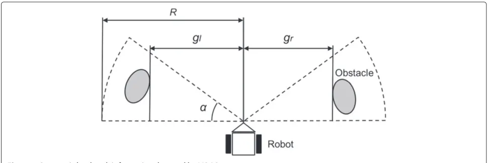
Figure 3 shows how the LIDAR is used in the MNPC. Scan ranges are set in front left and right of the robot. The length of these rangesRis 6 m and the angleαis 30 degrees. The reason of which these ranges are set at the sides is that the LIDAR is used as compensating a lateral error from the desired path. The minimum lateral lengths measured in each range are used as geometric informa-tionG, and they are denoted asglandgr. The information
recorded in nodenis denoted asgn=
gl,ngr,n
.
Table 1 An example of the database used on the MNPC
Travel Heading Magnetic Geometric
distance direction informationM informationG
d0 θ0 m0 g0
d1 θ1 m1 g1
. . . . . . . . . . . .
dn θn mn gn
. . . . . . . . . . . .
The MNPC controls the robot as converging all components of ec to zero by controlling robot’s angular
velocityω.
We achieved outdoor autonomous navigation over 2 km by using the MNPC [6]. However, the MNPC has a fatal problem.
A fatal problem of the MNPC
As we mentioned in the previous section, swerving from the desired path is a fatal problem when using the linear magnetic map. However, the trajectory easily meanders in an area with magnetic anomalies since the control using magnetic sensor readings does not work well. As the result, the robot easily swerves from the path. In MNPC, geometric information is used for compensating an error produced by the meander. However, if ambi-ent geometric information is also dynamically changed, the compensation does not work well. This means that it is difficult to adopt the MNPC in dynamic environment navigation.
Avoiding moving objects, which intersect the desired path, is also fatal problem since the robot swerves from its desired path. However, if the robot can precisely navigate on its desired path, avoiding moving objects is not neces-sary. Therefore, in our navigation strategy, the robot will stop when an obstacle appears in front of it.
Proposed method
The key idea of our proposed method is to use only effec-tive sensor readings for robot’s control. The MNPC has three different information of magnetic sensor, LIDAR, and encoders readings. The quality of these information differs from each others. For instance, there is a case where LIDAR readings are not containing incorrect infor-mation even if magnetic sensor readings are containing incorrect information. In this case, meandering the trajec-tory can be prevented if LIDAR readings can be only used for the control. Therefore, we divide the navigation mod-ule of the MNPC into several modmod-ules, and propose to use every module based on the DCS.
Figure 4 shows the system scheme of the proposed method. Localization is performed by using magnetic informationM, magnetic sensor readingsmt, and encoder
readingsat. A state of the robot at timetXtis expressed
by a travel distancedtand a heading directionθt.
The robot localizes its own travel distancedand head-ing directionθby using only the magnetic informationM. Currently, the robot is locating at nodenand observing magnetic informationmtand geometric informationgt,
the deflections used for robot’s controlecare determined
as follow:
ec=
θy,n−θy,t gl,n−gl,t gr,t−gr,n
. (1)
There are several navigation modules in the system and each module called a “navigator”. Each navigator is defined to navigate the robot based on each sensor read-ings. Each navigator independently send a control input
ui(i = 1, 2,. . .,k) and a priority pi to the
manage-ment module. This managemanage-ment module then selects an actual control inputubased on the priority value, which is determined by comparing external sensor readings (mtandgt) with the database (mnandgn). Thegtis
geo-metric information observed at timet. If sensor readings are unreliable, the priority value of the navigator using
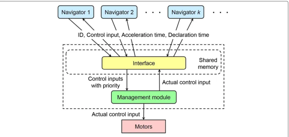
Figure 4System figure of the proposed method.
those sensor readings is set to a low value. With this method, an reliable navigator can be selected.
The configuration our DCS is shown in Figure 5. Several navigators are executed in parallel. All the sensor read-ings are temporarily stored in the shared memory, which can allow all the navigators to access to. In this study, we used four navigators; (1) navigator based on odometry, (2) navigator based on geometric information, (3) navigator based on magnetic information, and (4) navigator based on magnetic and geometric information (MNPC).
Navigator based on odometry
If the robot is locating at node n, and θt is its actual heading direction, the deflectioneocan be determined as
follow:
eo=θn−θt. (2)
The navigator converges this deflection to zero by control-ling the angular velocity.
Figure 6Overview of the experimental course.
Navigator based on geometric information
If the robot currently locates at nodenand a geometric informationgt =
gl,tgr,t
is observed, the deflectionel
can be determined as follow:
el=
gl,n−gl,t gr,t−gr,n θn−θt
. (3)
The navigator converges all components ofel to zero by
controlling the angular velocity.
Navigator based on magnetic information
If the robot is locating at nodenandmt =
bz,tθy,t
is a magnetic information measured by the magnetic sensor, the deflectionemcan be determined as follow:
em=θy,n−θy,t. (4)
The navigator converges this deflection to zero by control-ling the angular velocity.
Table 2 Trajectory tracking errors from the desired path
Proposed method MNPC Magnetic Geometric Odometry
Average [m] 0.171 0.673 0.481 0.479 0.720
Standard deviation [m] 0.130 0.686 0.586 0.643 0.620
Navigator based on magnetic and geometric information
This navigator uses magnetic and geometric informa-tion, namely it is the MNPC. The detail of the MNPC is mentioned above.
Priority determination
A priority value of each navigator pi is determined as
follow:
pi=
αi (used sensor readings are reliable)
0 (used sensor readings are unreliable), (5)
where αi are plus fixed numbers. We set a high fixed number to a navigator, which can precisely navigate the robot. The order of the priority vales is as following; (1) the MNPC (2) navigator based on magnetic information (3) navigator based on geometric information (4) naviga-tor based on odometry. It was defined on the basis of our experiences.
In a case where moving objects across nearby the robot, the navigator using geometric information does not work well. The reliability of LIDAR readings is determined by using these difference values|gl,n−gl,t|and|gr,t−gr,n|. If
the values exceed 1.0 m, the priority of the MNPC and the navigator based on geometric information become zero.
In a case where the magnetic sensor measures noise, navigator using magnetic information does not work well.
The reliability of magnetic sensor readings is determined by using a variablepm, which is expressed as follow:
pm=1− |
bz,n−bz,t| bmax
, (6)
wherebmaxis a difference value of maximum and
min-imum magnetic intensitybzmeasured by used magnetic
sensor. In this study, we definedbmax = 1 on the basis
of our experiences. Magnetic sensor readings are reliable when the value ofpmcloses to 1. Ifpmis less than 0.998,
the priority value of the the MNPC and the navigator based on magnetic information become zero.
Results and discussion Navigation experiment
We conducted a navigation experiment for verifying the effectiveness of the proposed method by comparing five navigation methods; the proposed method and four navi-gators in the proposed method. Note that the experiment was conducted after three days of database construction.
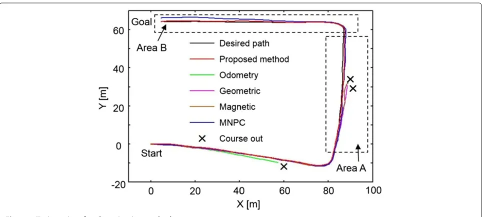
Figure 6 shows the overview of the experimental envi-ronment. In this environment, there are some difficult areas for navigation; landmark-less area, bicycles’ parking area, and area with disturbed magnetic field. The trajec-tories by each method are shown in Figure 7. The tra-jectories were obtained by using our localization method [20], and obviously outlier was manually corrected. As can
Figure 9Trajectories in Area A in Figure 7.
be seen from Figure 7, only the proposed method and the MNPC could complete the autonomous navigation. Table 2 shows average and standard deviation of trajec-tory tracking error of each method. From the table, we could confirm that the proposed method achieved the most precise navigation.
Figure 8 shows priorities of each navigator in the proposed method. These priorities were dynamically changed. By combining the results of Figure 8 and Table 2, it showed that the control method based on the DCS effectively performed in the environment and provided the robot a precise navigation.
Figure 9 and Figure 10 are enlarged figures of Area A and B in Figure 7. In Area A, the trajectory of the nav-igator using magnetic information meandered since the magnetic field was disturbed. Moreover, in Area B, the trajectory of the MNPC swerved since state of the bicy-cles’ parking area was changed from the time of database construction. Even if the proposed method used both of magnetic and geometric information, precise navigation could be conducted. This means that the MNPC was improved by using the DCS.
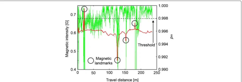
Moreover, Figure 11 shows magnetic intensity on the desired path (red line) and value of pm determined by
Figure 11Magnetic intensity on the desired path (red line) and reliability (green line) obtained in autonomous navigation.
Eq. (6) (green line). The value of pm decreased around
magnetic anomalies, which were used as magnetic land-marks and some other areas. This shows that the variable
pm effectively worked in the proposed method. From
these results, the effectiveness of the proposed method was shown.
Simulated guiding demonstration
We conducted a simulation experiment of the guiding demonstration in our campus. Figure 12 shows the exper-imental scenario. The robot ran on the desired path from left to right and a guidance target followed by walk-ing behind of the robot. In addition, three groups of pedestrians passed by the robot as shown by the yellow arrows.
Figure 13 shows the result of the experiment. The robot stably navigated on the desired path even if the three groups walked around the robot. When the groups passed nearby the robot, the navigators using geometric infor-mation did not work and the robot was controlled by the
navigator based on magnetic information or the navigator based on odometry. As the result, the robot did not mean-der and the navigation was not influenced by the moving objects.
After the groups walked away, the robot used geomet-ric information for the lateral error compensation and a stable navigation was restored. The experimental result shows that the proposed method can be adopted to navi-gation in a busy pedestrian walkway.
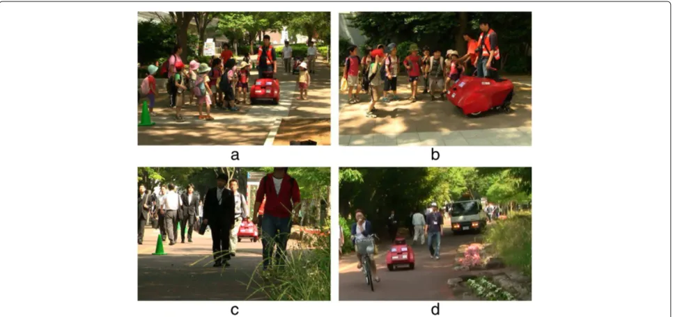
Guiding demonstration in ROBOMEC2013
The guiding demonstration using autonomous mobile robots was held in Tsukuba-city, Japan, and we took part in this demonstration. In this demonstration, robots should lead persons from the start area to the destination in actual busy pedestrian walkway.
The views of this demonstration are shown in Figure 14. Figure 14(a),(b) show a case where many children were gathered in front of the robot and they walked with the robot. Moreover, the case where many pedestrian come
Figure 13Experimental result of the simulated guiding demonstration.
and go around the robot often occurred (see Figure 14(c)). These cases were similar to the experiment, which we con-ducted in our campus. In these cases, the navigator based on magnetic information or the navigator based on odom-etry were performed. As the result, stable navigation could be performed even if available geometric landmarks could not be observed.
Figure 14(d) shows an interesting case where there was a truck nearby the desired path. The truck influenced magnetic field and blocked detection of available geo-metric landmarks. In this case, the navigator based on odometry was performed. The robot ran approximately 10 m and achieved autonomous navigation. Autonomous navigation based on odometry is usually unsuitable, how-ever, in this case, it is suitable since there are no effective
information. Our method could select navigator based on odometry and realized stable navigation in the dynamic environment.
In one demonstration, the robot ran approximately 700 m. We conducted 27 guiding demonstrations and our robot could perfectly accomplished all demonstra-tions. From these results, the robustness of the proposed method was confirmed.
Conclusions
In this paper, we proposed a navigation method for improving the MNPC. The improvement could be fulfilled by using the DCS. In our method, since the linear mag-netic map is used for localization, swerving from a desired path is fatal problem. Our proposed method could solve
the problem and achieved precise autonomous navigation in dynamic outdoor environments, since used DCS can select the navigator, which precisely navigates the robot on the desired path. We took part in the guiding demon-stration held in the central of Tsukuba-city, Japan. In the demonstration, we conducted 27 guiding, and miss guid-ing was not done. From these results, we showed the effectiveness and robustness of the proposed method.
Competing interests
The authors declare that they have no competing interests.
Authors’ contributions
NA and SAR proposed the navigation method. NA and KI are members of the developing team. NA, KI, and KO conducted the experiments. All authors have read and approved the final manuscript.
Acknowledgements
This study was supported by KAKENHI (25420210). Moreover, the first author was supported by Mr. Saito.
Author details
1Department of Innovation System Engineering, 7-1-2, Yoto, Utsunomiya-shi,
Tochig, Japan.2Department of Electrical and Information Engineering, Oyama
National College of Technology, 771, Nakakuki, Oyama-shi, Tochigi, Japan.
Received: 14 January 2014 Accepted: 20 June 2014
References
1. Lee SY, Yang HW (2012) Navigation of automated guided vehicles using magnet spot guidance method. Robot Comput-Integr Manuf 28(3):425–436
2. Maaref H, Barret C (2002) Sensor-based navigation of a mobile robot in an indoor environment. Robot Autonomous Syst 38:1–18
3. Rahok SA, Ozaki K (2008) Localization system based on magnetic map for indoor mobile robot. In: JSME conference on robotics and mechatronics. Nagano, Japan, 5-7 June 2008 (in Japanese)
4. Rahok SA, Shikanai Y, Ozaki K (2011) Navigation using an environmental magnetic field for outdoor autonomous mobile robots. Adv Robot 25(13-14):1751–1771
5. Nagatani K, Kushleyev A, Daniel DL (2012) Sensor information processing in robot competitions and real world robotic challenge. Adv Robot 26(14):1539–1554
6. Akai N, Rahok SA, Inoue K, Ozaki K (2013) Implementation of a long-distance navigation method of low cost structure that combines a localization using magnetic information and a lateral position
compensation. Trans Japan Soc Mech Eng 79(799):681–690 (in Japanese) 7. Brooks RA (1986) A robust layered control system for a mobile robot. IEEE
J Robot Automation 2(1):14–23
8. Rosenblatt JK (1997) DAMN: a distributed architecture for mobile navigation. J Exp Theor Artif Intell 9(2-3):339–360
9. Morales Y, Carballo A, Takeuchi E, Aburadani A, Tsubouchi T (2009) Autonomous robot navigation in outdoor cluttered pedestrian walkways. J Field Robot 26(8):609–635
10. Yoshida T, Irie K, Koyanagi E, Tomono M (2010) A sensor platform for outdoor navigation using gyro-assisted odometry and roundly-swinging 3D laser scanner. In: International conference on intelligent robots and systems, Taipei, Taiwan, 18-22 October 2010
11. Irie K, Yoshida T, Tomono M (2012) Outdoor localization using stereo vision under various illumination conditions. Adv Robot 26(3-4):327–348 12. Chen Y, Medioni G (1991) Object modeling by registration of multiple
range images. In: International conference on robotics and automation, California, United States, 9-12 April 1991
13. Dellaert F, Fox D, Burgard W, Thrun S (1999) Monte Carlo localization for mobile robots. In: International conference on robotics and automation, Michigan, United States, 10-15 May 1999
14. Bento LC, Nunes U, Moita F, Surrecio A (2005) Sensor fusion for precise autonomous vehicle navigation in outdoor semi-structured
environments. In: International conference on intelligent transportation systems. Congress Center MesseWienNeuVienna, Austria, 13-16 September 2005
15. Suksakulchai S, Thongchai S, Wilkes DM, Kawamura K (2000) Mobile robot localization using an electronic compass for corridor environment. In: International conference on systems, man and cybernetics, Nashville, United States, 8-11 October 2000
16. Haverinen J, Kemppainen A (2009) Global indoor self-localization based on the ambient magnetic field. Robot Autonomous Syst 57:1028–1035 17. Gozick B, Subbu KP, Dantu R, Maeshiro T (2011) Magnetic maps for indoor
navigation. IEEE Trans Instrum Meas 60(12):3883–3891
18. Frassl M, Angermann M, Lichtenstern M, Robertson P, Julian BJ, Doniec M (2013) Magnetic maps of indoor environments for precise localization of legged and non-legged locomotion. In: International conference on intelligent robots and systems, Tokyo, Japan, 3-8 November 2013 19. Woong K, Roh KS, Sung HK (2006) Particle filter-based heading estimation
using magnetic compasses for mobile robot navigation. In: International conference on robotics and automation, Florida, United States, 15-19 May 2006
20. Akai N, Inoue K, Ozaki K (2014) Autonomous navigation based on magnetic and geometric landmarks on environmental structure in real world. J Robot Mechatronics 26(2):158–165
doi:10.1186/s40648-014-0021-8
Cite this article as:Akaiet al.:Development of magnetic navigation
method based on distributed control system using magnetic and geometric landmarks.ROBOMECH Journal20141:21.
Submit your manuscript to a
journal and benefi t from:
7 Convenient online submission
7 Rigorous peer review
7 Immediate publication on acceptance
7 Open access: articles freely available online
7 High visibility within the fi eld
7 Retaining the copyright to your article