863 |
P a g e
SMART VEHICLE CONTROLLED SYSTEM
Sneha Mohan Shingate
1, Y. V. Chavan
21,2
Padmabhooshan Vasantdada Patil Institute Of Technology, Pune, MS (India)
ABSTRACT
The ARM7 controller is used in many applications. In this paper it is used as the core controller, to control the entire vehicle. A voice recognition module will be used for human interaction with the vehicle. This module will be at the transmitter side i.e. with the person, which gives the desired commands. The controller used at the transmitter side is PIC controller. This signal will be received by the controller at the receiver end placed on the vehicle for controlling. In controlling mainly four operations will be performed i.e. forward, stop, left, right in this prototype. To provide safety IR sensors will be used which gives feedback at the receiver end whenever there is any obstacle. For real time operation µcos-ii will be used to enhance the performance of system.
Keywords:
Control system, Embedded, LPC2148, PIC 16F876A, Wireless Robot, µcos-ii.
I. INTRODUCTION
Improvements in hardware technology have resulted in low-cost controllers which are composed of a single chip
with embedded memory, processor, and peripherals. The advancement in technology is in a rapid progress. New
ideas are proposed every time in different sectors. If we consider the automobile field there is a tremendous rise
in light and heavy vehicle. Many automobile companies are coming with new ideas in order to increase their
sales and to gain top level in market.
ARM architecture is designed to allow very small, with high performance implementation. This simplicity leads
to very small implementations which allow devices with very low power consumption. Now a day’s most
industries are using this controller to develop their product. One of the examples includes the I-phone 5 mobile
which uses ARM 7 processor.
ARM is a RISC architecture which has the following features:
A large uniform register file.
A load-store architecture, where data processing operations only operate on register content, not
directly on memory contents.
Simple addressing modes.
Uniform and fixed length instruction fields.
High performance, low code size.
Low power consumption and silicon area.
ARM based embedded system has good performance and portability; therefore it has been widely used in
various industries. Different operating systems can be ported easily on this controller.
Volume No 03, Special Issue No. 01, March 2015 ISSN (online): 2348 – 7550
864 |
P a g e
Simple addressing modes.
Uniform and fixed length instruction fields.
High performance, low code size.
Low power consumption and silicon area.
ARM based embedded system has good performance and portability; therefore it has been widely used in
various industries. Different operating systems can be ported easily on this controller.
II. CONTRIBUTION BY THE PREVIOUS RESEARCHERS
Here different papers are studied and analyzed based on the approaches used by the different researchers and
modifications are made to provide more reliability in the proposed system.
Chunru Xiong and Jufang Hu, invented the Smart Vehicle Control System based on ARM and μC/OS-II”
Approach used here is that the system uses LPC2138 of ARM 7 as the core controller in the smart vehicle so as
to achieve a real-time operation system (OS) μC/OS-II. The real-time μC/OS-II enhances the performance of
control and simplifies the design and management of software. In addition, this system uses voice-driven
principle, improving the human interaction between machines and operators. The utilization of high-precision of
ultrasonic sensors on obstacle avoidance robot provides a guarantee for safety. And the usage of LCD as the
machine interface facilitates the debugging and control of robot.
Zhaohui Wu, Qing Wu, Hong Cheng, Gang Pan, Minde Zhao, and Jie Sun invented a semantic and adaptive
middleware platform, i.e., ScudWare, for smart vehicle space.
Approach used here present ScudWare, which is a semantic and adaptive middleware platform for the smart
vehicle space in ubiquitous computing environments. It achieves the synchronization and the adaptability
aspects of the smart vehicle space at the multiagent, context-aware, and adaptive component level according to
the semantic information. It also presented a mobile music prototype system and gave a scenario in the smart
vehicle space, which demonstrates the ScudWare’s performance.
Shufu Mao and Tilman Wolf briefly introduce monitoring subsystem that operates in parallel with the embedded
processor. The monitor verifies that only processing steps are performed that match up with the originally
installed application.
Through the literature survey it has come to know that designing of smart vehicle and its control system was
based on various processors and with wired system for the control signals. This carries lots of disadvantages as
wire itself was the problem in addition to the hardware requirement along with processor.
III. PROPOSED SYSTEM
865 |
P a g e
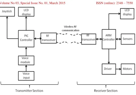
Fig. 1: System Block Diagram3.1. Transmitter side
As shown in fig 1 the user will give the voice commands to the voice recognition module. Initially the voice
module is programmed to the commands which will be accessible. The commands will be processed in PIC
controller and the signals will be transmitted wirelessly by RF module which is basically a transceiver. This
transceiver will also receive the signals coming from receiver end. This signal commands will be displayed on
LCD connected to the controller. A joystick is also connected to the controller for controlling the vehicle if
voice commands are not required.
3.2. Receiver side
As shown in the fig 1 the signals or the commands transmitted from the transmitter side will be received at the
receiver end to the RF module. These signals will be processed by the ARM controller placed on the vehicle. As
per the commands the driver- motors will be controlled i.e. to move forward, backward, left or right. A sensor is
attached to the vehicle which is used to detect if there is any obstacle in front of the vehicle. If an obstacle is
detected the sensor will be on and the controller will send a signal to transmitter end through RF. The LCD on
transmitter side will give a display as obstacle detected and the corresponding action will be taken by the user.
The controller is also connected to an LCD to display the commands given to it.
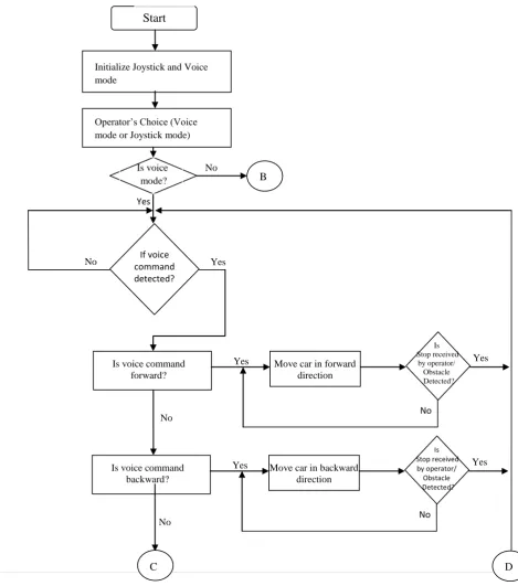
IV. SYSTEM FLOWCHART
The system flowchart is shown in Fig 2. The flowchart is divided into two parts based on the operator’s choice.
Volume No 03, Special Issue No. 01, March 2015 ISSN (online): 2348 – 7550
866 |
P a g e
powered on. Depending upon the operator’s choice voice mode or joystick mode the system will operate
accordingly at the receiver side. Consider operator’s choice is voice mode. Voice command is taken as input
to the voice module; if the voice is not detected then voice command will be taken again. If the voice is detected
then depending upon the command i.e., forward, backward, right or left the vehicle will move accordingly. The
vehicle will move in the respective direction until it receives stop command or if an obstacle is detected. The
vehicle will stand still once reached the destination.
Consider operator’s choice is joystick mode; the system will work according to the flowchart B as shown in the
Fig 2. Initially the joystick position will be detected and depending upon the position of joystick i.e., forward,
backward, right or left the vehicle or the system at the receiver side will move in respective direction until the
operator stops it.
Start
Initialize Joystick and Voice mode
If voice command detected?
Is voice command forward?
Move car in forward direction
Is Stop received
by operator/ Obstacle Detected?
Yes
No
Yes Yes
Is voice command backward?
Move car in backward direction
No
Yes Yes
No
No No
Operator’s Choice (Voice mode or Joystick mode)
Is voice mode?
Yes
No
B
Is Stop received
by operator/ Obstacle Detected?
867 |
P a g e
Is voice commandright?
Move car in right direction
No
Yes Yes
Is voice command left?
Move car in left direction
No
Yes Yes
No No Stand still Is Stop received by operator/ Obstacle Detected? Is Stop received by operator/ Obstacle Detected? Reached destination? Yes No
C D
B
Detect Joystick position
Is Joystick position forward?
Move car in forward direction
Yes
No
Is Joystick position backward?
Move car in backward direction
Yes
No
Is Joystick position right?
Move car in right direction
Yes
No
Is Joystick position left?
Move car in left direction Yes No Stand still Reached destination? Yes No
Volume No 03, Special Issue No. 01, March 2015 ISSN (online): 2348 – 7550
868 |
P a g e
V. CONCLUSIONS
These system uses voice driven principle which improves human machine interaction and makes the control of
the system simple. The use of IR sensors helps the vehicle to prevent from damage. Use of ARM
microcontroller LPC 2148 and real time ucos-ii improves the speed of operations.
The system can be used as a carrier of the mobile robot, residential patrol, bomb detecting and diffusion, site
investigation and many other areas.
REFERENCES
[1] Chunru Xiong, Jufang Hu, “Design of smart vehicle control system based on ARM and ucos-ii”,
International Conference on Computer Science and Electronics engineering, 2012.
[2] Zhang, G Liu, “Study on Approach of Determining Size of μC/OS-II Task Stack”., Journal of Computers,
2011.
[3] Gupta, M.Y Chow, “Networked control system: Overview and research trends”, IEEE Transactions on
Industrial Electronics, 2010.
[4] Marti P, “Design of an embedded control system laboratory experiment”, IEEE Transactions on Industrial
electronics, 2010.
[5] Han, S Sezaki,” Development of an optical vehicle to grid aggregator for frequency regulation”, IEEE
Transactions on smart grid, 2010.
[6] Mao, Wolf,” Hardware support for secure processing in embedded systems”, IEEE Transactions on
Computers, 2010.
[7] Wang, F.X., Q.L. Tan, and J.M. Li, “Design of the High-Precision Signal Generator Based on ARM”,
Applied Mechanics and Materials, 2011.
[8] Wu, ScudWare,” A semantic and adaptive middleware platform for smart vehicle s p a c e ”, IEEE
Transactions on Intelligent Transportation Systems, 2007.
[9] Aria Nosratini,Todd E. Hunter and Ahmadreza Hedayat, “Cooperative Communication in Wireless
Networks,” IEEE Communications Magazine , October 2004.
[10] Sandeep S. Kulkarni and Mahesh Arumugam, “TDMA Service for Sensor Networks,” International