International Journal of Advanced Technology in Engineering and Science www.ijates.com
Volume No.02, Issue No. 12, December 2014 ISSN (online): 2348 – 7550
ACHIEVING MECHANICAL STABILTY OF ROTARY
KILN BY FEM
Sumesh Krishnan
B.E, M.B.A., M.Tech
ABSTRACT
Rotary kilns are found in many processes that involve solids processing. These include drying, incineration,
mixing, heating, cooling, humidification, calcinations ,reducing, sintering and gas-solid reactions (Jauhari et.
al. 1998). The most common and industrially important application of rotary kilns is in cement production; all
major producers use the rotary kiln as their equipment of choice.
Rotary kilns are amongst the most well-established unit operations in the process industry, yet are amongst the
least understood. They can be used for 3 purposes: heating, reacting and drying of solid material, and in many
cases, they are used to achieve a combination of these aims. In the design of kilns, there are four important
aspects to consider from a process engineering point of view, and these are heat transfer, flow of material
through the rotary kiln, gas-solid mass transfer and reaction.
Roller and shaft of Cement Rotary Kiln supporting roller is exposed to high stresses under heavy working
situation. High Stresses because of big kiln dimensions cause damage to roller and shaft of supporting roller
mechanisms. This requires that, decreased stresses provides longer life and decreased damaged to roller and
shaft of supporting roller with material properties and working conditions..
Active researching and development of the mechanics of cement factories equipment's are not studied in the
cement industry. Researching roller and shaft of supporting roller will be useful in the cement industry and is
not a good candidate for experimentation due to economical reasons. However, engineers use model in the
computer analysis program with original dimensions of subjects and engineers do complex model analysis with
the aid of computer. The material properties and working situations are given to analysis program on the
computer veritably. Roller and shaft model is drawn and analysis done in order to get critical stresses results.
I. INTRODUCTION
The investigations show that the causes of refractory failure and poor durability of refractory in large diameter
kilns are due to the following factors.
Grade & lining methods of refractory
Operational influence
Mechanical stresses on the refractory.
The paper also discusses the causes of refractory lining failure, component breakdown with reference to
mechanical stresses which are due to the following factors:
569 |
P a g e
Kiln shell warping Kiln alignment
Mechanical condition of kiln
II. KILN ALIGNMENT
2.1 Definition
A kiln is supposed to be aligned if its rotating axis is rectilinear. In other words, if the rotating centers of shells
at centre of tyres are joined together, these should form a straight line, in horizontal as well as vertical plane.
2.2 Cold Kiln Alignment
This can be carried out by taking the measurements while the kiln is stopped. The cold alignment has many
limitations, however, a few are listed below:
measurements are not very accurate
wear of tyres, rollers and chairs is not considered
effect of temperature is not considered
Despite above limitations, this method of alignment is in use in many cement plants, since its cost is quite low
as compared to the hot kiln alignment.
2.3Hot Kiln Alignment
In this method, the readings are taken while the kiln is operating at full production. The readings obtained are
fairly accurate. However, this method of alignment is costly.
2.4 Alignment Requirement
For improving the refractory life the kiln should be aligned every 2 years preferably by hot alignment method.
III. MECHANICAL CONDITION OF KILN
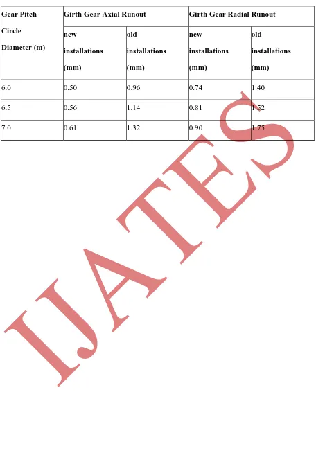
3.1 Kiln Shell Runout
3.1.1 Radial and Facial Runout of Girth Gear
To obtain extended life of girth gear and pinion the runouts should not exceed the acceptable limits. When the
readings show excessive runouts the girth gear should be re-aligned.
3.2 Pinion-Girth Gear mesh
3.2.1 Skew of Rollers
Excessive skewing and wrong skewing of rollers may create heavy thrust reaction on the bearings and at times
vibrations which are detrimental to the lining life.
3.3 Lubrication of Tyre
Life of refractory lining can be improved by:
International Journal of Advanced Technology in Engineering and Science www.ijates.com
Volume No.02, Issue No. 12, December 2014 ISSN (online): 2348 – 7550
Continuously monitoring the tyre creep, temperature of tyre and shell. Cooling the shell when the limits forcreep and temperature are critical.
Avoiding rapid heating and cooling of kiln
Checking and correcting alignment of kiln every 2 years and
Maintaining the kiln in a good mechanical condition
- extended lifetime of the refractory lining and elimination of the lining loss caused by the rotary kiln
mechanical instability
- energy savings
- enhanced lifetime of the shell, tyres, stop-blocks, support rollers, shafts and bearings
- reduced wear of a gear ring, pinion and drive
- elimination of cracks and overheating of the kiln shell
Typical Kiln Failure Symptoms
Hot bearings Cracks Mechanical wear Lining loss
On bearing
journal
On thrust
journal
In kiln
shell
On roller
shaft
On support
roller and
tyres
Between
tyre and
kiln shell
Between
tyre
Under
tyres
Kiln geometry Kiln geometry Kiln geometry Kiln geometry
Kiln shell ovality Kiln shell ovality Kiln shell ovality
Kiln crank Kiln crank
Kiln crank
Kiln crank
Axial balance Axial balance
Lubrication Corrosion Lining quality
An extensive problem if we include thermal radiation (loads), chemical mixing, particulogy would be
numerically expensive to solve. Optimal state of balance, dynamics, power savings, reduced maintenance,
increased productivity can only be achieved in near future when cost of computation is more economically
feasible
3.4 Kiln Geometry Analysis
The high reliability and the ability to predict breakdowns of a rotary kiln critically depend on its geometry.
Changes such as sinking of foundations, uneven mechanical wear or an inadequate repair can lead to
overloading of individual components. This condition then gradually develops into a full-fledged damage and
571 |
P a g e
Rotary kilns should be therefore carefully aligned in order to reduce to minimum torsion and stress in the kiln
shell, i.e. the factors cause excessive mechanical wear and can negatively influence the lifetime of refractory
lining, rollers, bearings and other components.
Analyzed elements:
- kiln axis (spatial course)
- kiln slope
- roller operating angles
- deviation of supporting roller axes from the kiln axis (spatial)
- diameters and profiles of the supporting rollers
- diameters and profiles of the tyres
- tyre and gear ring wobbling
-
thermal differencesIV. MATERIALS AND METHODS
4.1 Finite Element Analysis
In this finite element analysis the continuum is divided into a finite numbers of elements, having finite
dimensions and reducing the continuum having infinite degrees of freedom to finite degrees of unknowns. It is
assumed that the elements are connected only at the nodal points. The accuracy of solution increases with the
number of elements taken. However, more number of elements will result in increased computer cost. Hence
optimum number of divisions should be taken. In the element method the problem is formulated in two stages
The Element Formulation
The System Formulation
4.2 Basic Steps in the Finite Element Method
Discretisation of the domain
Incorporation of boundary conditions
Formation of the element loading matrix
Formation of the overall loading matrix
Solution of simultaneous equations
Calculation of stresses or stress resultants
V. RESULTS
In the scope of:
- FEA analysis of the support roller;
International Journal of Advanced Technology in Engineering and Science www.ijates.com
Volume No.02, Issue No. 12, December 2014 ISSN (online): 2348 – 7550
determination of maximal stresses values and location in roller’s shaft material; guidelines for improvements and reinforcement methods to reduce stresses;
5.1 Actual Stress Test Results
5.1.1 Brief
1. The analysis was performed according to research requirements.
2. the purpose / reason of the analysis is given subsequently.
3. the document shows the condition of the facility as on: 2013-11-28 (reception of the latest data);
4. all data included herein and in the attached appendices were stored in the computer database;
5. particularly important remark/ guideline – in bold for easier identification,
(R) - remark/ guideline – repetition/ reminder of the contents of the previous inspection report which is still
valid,
- additional information/ theoretical foundation for easier understanding of the remarks/ guidelines.
5.1.2 Description of the problem
The plant is reporting problems of abnormal sound coming form the support roller of rotary kiln #1 - first
support pier from the inlet side. In the past there was a breakdown of the roller shaft. Based on the email
correspondence and revision of documentation, it has been stated, that there is a need of FEA analysis of roller
shaft to determine the stresses value for the given (actual) load parameters.
Data and assumptions for analysis
Data received from the industry
- construction drawing of the roller – according to the Drawing 1 – see enclosure no.1; - construction drawing of roller raceway - according to the Drawing 2 – see enclosure no.2; - construction drawing of roller shaft – according to the Drawing 3 – see enclosure no.3;
- roller shaft material EN9 with technical specification according to the enclosure 4 – BS070M55(EN9), Rm = 715MPa – ultimate tensile strength;
- total weight of the object (including charge material) considered as the load to the support system mt =
416tons;
- the most loaded support we consider middle pier (P2), force acting on the rollers equals 40% of total weight
of the object R = 166.4tons;
- angle of support rollers at the kiln center is 600, load component acting on the single roller FR = FL =
96.1tons; Load per roller = (1273.18/2)*cos 30
- coefficient of dynamic load (considering 3.3 RPM) we assume 1.1 results in dynamic load value of FR(=L) dyn = 105.7tons (per single roller) STOP.
- for the complementary analysis there should be also included tension coming from the fitting of the raceway
573 |
P a g e
assembly quality. We have not taken this into consideration but the client should notice that this will
additionally increase stresses value inside the shaft;
- we have assumed that the contact between roller and tire raceway is continuous on the total available width
of ring raceway, coefficient of dynamic load is considering some additional increases of the load force but in
typical, proper working conditions,
- we have assumed there is no hidden crank of shell and no large misalignment of support system axis.
5.1.3 FEA Analysis and Results
Drawing below is showing the construction of the roller assembly.
For our analysis we have considered different cases of bushings position.
If the bearing is not self aligning the following cases can appear:
Case 3. Right and Left Bushing Nonparallel to the Shaft Journal
In each case the distance between reaction forces position is different.
In each case the equivalent of deformation and stress distribution is different also (see next pages).
International Journal of Advanced Technology in Engineering and Science www.ijates.com
Volume No.02, Issue No. 12, December 2014 ISSN (online): 2348 – 7550
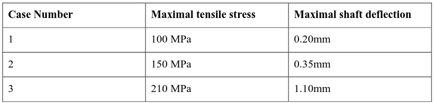
Finally, if the bearing is not self aligning, the following cases of deformation can appear:
max. deflection = 0,20mm
Case 1. Bushings parallel to the shaft journal.
max. deflection = 1,10mm
Case 3. Right and left bushing nonparallel to the shaft journal.
max. deflection = 0,35mm
Case 2. Right bushing nonparallel to the shaft journal.
5.1.4 Deformation of the Roller Shaft, For Non-Self Aligning Bearings
And finally, if the bearing is not self aligning, the following cases of stresses can appear (calculated according to
Huber hypothesis): And finally, if the bearing is not self aligning, the following cases of stresses can appear (calculated according to Huber hypothesis):
max. stresses = 100MPa
Case 1. Bushings parallel to the shaft journal.
max. stresses = 210MPa
Case 3. Right and left bushing nonparallel to the shaft journal.
Table 1. Strength results determined for each case.
max. stresses = 150MPa
Case 2. Right bushing nonparallel to the shaft journal.
Case number Maximal tensile stress Maximal shaft deflection
575 |
P a g e
Non Self Aligning Bearings
Case Number
Maximal tensile stress
Maximal shaft deflection
1
100 MPa
0.20mm
2
150 MPa
0.35mm
3
210 MPa
1.10mm
5.1.5 Commentary to the Obtained Results
Stop The most critical point of the shaft is always an entrance of the shaft inside the raceway bushing in in the analyzed cases the effect is amplified by the small step on the shaft 55mm wide 360 mm of diameter. This is the
place of stress accumulation what is shown on the picture bellow. 5 . C O M M E N T A R Y T O T H E O B T A I N E D R E S U L T S
STOP The most critical point of the shaft is always an entrance of the shaft inside the raceway bushing.
In the analyzed cases the effect is amplified bye the small step on the shaft 5mm wide 360mm of diameter. This is the place of stresses accumulation what is shown on the picture bellow.
Stresses on shaft and raceway joint (case 1) Stresses on the small step of the shaft (case 1)
Stresses obtained during analysis should be compared to the once resulting from
the shaft material strength
point of view. For the shaft material ultimate tensile strength value (Rm = 715MPa; value taken from the material
specification) we can calculate material effort for cyclically changing load (symmetrical compression / tension)
should not exceed krc = 118MPaSTOP ( krc = 0,5kr = 0,5(0,33Rm) ).
From the Table 1 you may see that only in case of perfect alignment of the roller
shaft and sleeve bearing,
this condition is assured. But such perfect conditions are not easy to assure. It could be a crank of shell
or not properly installed shim under the roller housing and we are suddenly over the stress limit.
As far as we concerned, such construction (length and diameters) of roller’s shaft is improper in reference
to the load condition, even if there is no additional forces acting on the kiln.
STOP 100MPa (case 1) vice versa 118MPa (limit for used material) is too small reserve and doesn’t assure
not limited live of roller from fatigue point of view !!!.
Fig Stresses On Shaft &Raceway Jont Fig.5.6Stresses On Small Step Of The Shaft
Stresses obtained during analysis should be compared to the once resulting from the shaft material strength point
of view. For the shaft material ultimate tensile strength value (Rm=715MPa; value taken from the material
specification) we can calculate material effort for cyclically changing load (symmetrical compression/ tension)
should not exceed krc=118MPa (krc=0.5kr=0.5(0.33Rm)).
From the table you may see that only in case of perfect alignment of the roller shaft and sleeve bearing this
condition is assured. But such perfect conditions are not easy to assure. It could be a crank of shell or not
properly installed shim under the roller housing and we are suddenly over the stress limit.
As far as we concerned, such construction (length and diameters) of roller's shaft is improper in reference to the load condition, even if there is no additional forces acting on the kiln. 100MPa (case 1) vice versa 118MPa (limit for used material) is too small reserve and doesn't assure not limited live of roller from fatigue point of view.
Guidelines
In relation to the above we suggest the following:
In urgent mode
International Journal of Advanced Technology in Engineering and Science www.ijates.com
Volume No.02, Issue No. 12, December 2014 ISSN (online): 2348 – 7550
slope. Any deflection of the frame under the roller which will not be compensated by the proper shimming will
created appearance of overload (even up to 100% more!);
In preventive mode
2. execute kiln alignment to optimize load to each roller;
3. check hidden crank (dynamic roller's deflection);
As a final aim
4. measure directly the real value of load per tire to confirm calculation data (the simulation of weights). If there
are any differences assume proportional change of calculated stresses and deflections;
Stop modify construction of the roller installing the busing on the shaft – inside the raceway (1000mm of length, OD=455 mm, ID=355mm; it requires boring of raceway and assure proper small interference fit).
Tensile stress value in this case will go down to 50MPa-50% lower (for case 1).
See below graphs with results of appropriate simulation; 6 . G U I D E L I N E S
In relation to the above we suggest the following:
6.1 IN URGENT MODE
1. STOP check and assure proper alignment of the bearing sleeve to the shaft journal.
Our simulation of different cases (1, 2 & 3) shows that slope of the bearing sleeve should be exactly like the global roller shaft slope. Any deflection of the frame under the roller which will not be compensated by the proper shimming will create appearance of overload (even up to 100% more !);
6.2 IN PREVENTIVE MODE
2. execute kiln alignment to optimize load of each roller; 3. check hidden crank (dynamic rollers’ deflections);
6.3 AS A FINAL AIM
4. measure directly the real value of load per tire to confirm calculation data (the simulation of weights). If there are any differences assume proportional change of calculated stresses and deflections;
5. STOP modify construction of the roller installing the bushing on the shaft – inside the raceway
(1000mm of length, OD = 455mm, ID = 355mm;
it requires boring of raceway and assure proper small interference fit).
Modification, we have proposed, will move the stress accumulation point farther form the raceway position. Tensile stress value in this case will go down to 50MPa – 50% lower (for case 1).
See below graphs with results of appropriate simulation;
Deformation after suggested modification (case 1) Stresses after suggested modification (case 1)
577 |
P a g e
VI. TABLES AND GRAPHS
Finite element modeling of the contact between two cylinders was examined in detail. The finite element
method with special techniques, such as the incremental technique of applying the external load in the input file,
the deformation of the stiffness matrix, and the introduction of the contact element were used. It was found that
initial loading using displacements as inputs was helpful in reducing numerical instabilities
To determine the accuracy of the present method for the bending stresses, both three dimensional and two
dimensional models were built in this chapter. So those FEA models are good enough for stress analysis.
VII. DISCUSSION
The contribution of the thesis work presented here can be summarized as follows: It was shown that an FEA
model could be used to simulate contact between two bodies accurately by verification of contact stresses
between two cylinders in contact and comparison with the Hertzian equations.
Correct Mechanical Balance can be concluded as an optimum state of the forces and stresses distribution acting
on kiln carrying system and the shell. The essential factors which determine this distribution are kiln geometry
(ovality) and mutual relations between rotation axes of kiln and support rollers (dynamic relations)
The analyses of the circumferential stresses and the contact stresses are implemented in the FE code
ANSYS. Subsequently, the required tangential friction stress is obtained in terms of the rolling and
sliding contact area condition. This study can be used to solve a fundamental contact problem
similar to the roller. The fatigue life curve can provide basis to adjust the axis line deflection more
effectively and prevent the accelerated fatigue damage of the roller. In comparison with the previous
results, the present results are longer and more rational as the multiaxial stress condition including the
circumferential stress and the tangential friction stress is considered
VIII. ACKNOWLEDGEMENTS
.
I would like to express the special thanks to my respected Dr. Mukul Shukla (MNNIT Allahabad), Dr.Sunil
Somani (Director Medicaps) and Management and staff at Allen Smith Engineers Ltd., Mumbai, who have
appreciated me directly and indirectly.
REFERENCES
[1] D.J.Van Dyk and L.Pretorius,1994 ―Analysis of dynamic effects in a Rotary Kiln System used for iron
production.Department of Mech.Engg. Rand Afrikaans University.
[2] David H.Johnson P.E, 2003., ― Principles of simulating contact between parts using Ansys
Pennysylvania.USA
[3] David. W.Broberg PE,1995 ―FEA &FMA reveal weak spots in Rotary Kiln Designs.
[4] Dinar Deshmukh 1989 ―Friction contact modeling techniques. University of Cincinnati.USA
[5] Dr. Sabah M. J Ali, Mr. Ahmed M Abdulla, College of Engg./University of Mosul. Study of the
Misaligment of the Rotary kiln. realtive to carrying roller centre in cement factories on the stress in
International Journal of Advanced Technology in Engineering and Science www.ijates.com
Volume No.02, Issue No. 12, December 2014 ISSN (online): 2348 – 7550
[6] Heng Long Li and Panos Papalambros,1984―A contribution to the optimal design of ride rings for
industrial Rotary Kiln.The University of Michigan.USA
[7] Li, Xuejun, Jiang, Linli, and Liu, Deshun. Research on supporting load distribution of large-scale rotary
kiln with multi-support and variable-stiffness. Chinese Journal of Computational Mechanics
22(2), 207-213 (2005)
[8] R.Saidur,M.S.Hossain,M.R.Islam,H.Fayaz,H.A.Mohammed,2011―Areview on Kiln system
Modeling,2011 Elseiver Vol.15, No. 2, pp 2487-2500.
[9] S N Vijayan et al. IJEST Vol. 4 NO.3. March 2012. ISSN:0975-5462.
[10] Tang, Ding. Studied on Rolling Contact Fatigue of Supporting Component of Large-Scale Rotary Kiln
(in Chinese), M. Sc. dissertation, Central South University, Changsha (2005)
[11] Technical Report – Jeoserves. Feb.2012. Research of deviation measurement geomatery of rotary klin.
between the supporting roller fatigue fate of rotary kiln and the axis line and how to predict its fate (in
Chinese). Chinese
Journal of Mechanical Engineering 42(10), 65-69 (2006)
[12] Ulas Ersin KULECKI,2003, ―Cement Rotary Kiln Support Roller Stress Analysis By using FEM.Izmir.
[13] Ulaú Ersin KÜLEKCø Cement Rotary Kiln Support Roller Stress Analysis and Decreasing of Stress
Stacking by Using Finite Elements Method
[14] Zhou, Xian, Li, Yilun, and Zhao, Xianqiong. Mechanical model and contact stress emulational
analysis of rotary kiln’s tyre (in Chinese). Journal of Central South University of Technology
33(5), 526-529 (2002)
Figure
579 |
P a g e
Fig. 3 Kiln Shell Profile After Multi Axial Deformations [Source: Geoservsex]Fig 5 Finite Element Model Of Roller And Tires With Boundary Conditions [16]
v
r
r
FH
FL
R
FLFR
600
R
FV FV
FH
FR
![Fig. 3 Kiln Shell Profile After Multi Axial Deformations [Source: Geoservsex]](https://thumb-us.123doks.com/thumbv2/123dok_us/9217826.1457311/12.595.76.496.102.738/kiln-shell-profile-multi-axial-deformations-source-geoservsex.webp)